Table of Contents
Advertisement
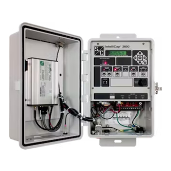
IntelliCap
2000 Automatic Capacitor Control
®
Table of Contents
Section
Qualified Persons . . . . . . . . . . . . . . . . . . . . . . . . . . 2
Read this Instruction Sheet . . . . . . . . . . . . . . . . . . . 2
Retain this Instruction Sheet . . . . . . . . . . . . . . . . . . . 2
Proper Application . . . . . . . . . . . . . . . . . . . . . . . . . . 2
Special Warranty Provisions . . . . . . . . . . . . . . . . . . . 3
Understanding Safety-Alert Messages . . . . . . . . . . . 4
Following Safety Instructions . . . . . . . . . . . . . . . . . . 4
Replacement Instructions and Labels . . . . . . . . . . . 4
. . . . . . . . . . . . . . . . . . . . . . . . . 5
Applicable Software . . . . . . . . . . . . . . . . . . . . . . . . . 6
Pre-Installation Checklist . . . . . . . . . . . . . . . . . . . . . 6
Optional In-Shop Setup Steps . . . . . . . . . . . . . . . . . 7
June 29, 2020
© S&C Electric Company 2014-2020, all rights reserved
Installation
Page
Section
On-Site Installation . . . . . . . . . . . . . . . . . . . . . . . . . . 8
Meter Base Mounting . . . . . . . . . . . . . . . . . . . . . . . . 9
Bracket Mounting . . . . . . . . . . . . . . . . . . . . . . . . . . .15
Harness Wiring . . . . . . . . . . . . . . . . . . . . . . . . . . . . .17
Voltage Sensing Source . . . . . . . . . . . . . . . . . . . . . .19
Voltage and Current Sensing . . . . . . . . . . . . . . . . . 20
Energize and Test the Control . . . . . . . . . . . . . . . . 22
Communication Equipment . . . . . . . . . . . . . . . . . . 23
Connecting Communication Hardware . . . . . . . . . . 24
. . . . . . . . . . . . . . . . . . . . . . . 25
. . . . . . . 26
Instruction Sheet 1024-510
Page
Advertisement
Table of Contents

Related Manuals for S&C IntelliCap 2000


Summary of Contents for S&C IntelliCap 2000
-
Page 1: Table Of Contents
IntelliCap 2000 Automatic Capacitor Control ® Installation Table of Contents Section Page Section Page Introduction Installing the Capacitor Control Qualified Persons . . . . . . . . . . . . . . . . . . . . . . . . . . 2 On-Site Installation . -
Page 2: Introduction
Safety Precautions on pages 4 through 5 . The latest version of this publication is available online in PDF format at sandc.com/en/support/product-literature/ . Retain this This instruction sheet is a permanent part of the IntelliCap 2000 Automatic Capacitor Control. Designate a location where you can easily retrieve and refer to this publication. Instruction Sheet... -
Page 3: Special Warranty Provisions
Special Warranty The standard warranty contained in S&C’s standard conditions of sale, as set forth in Price Sheets 150 and 181, applies to the IntelliCap 2000 Automatic Capacitor Control, Provisions except that the first paragraph of the said warranty is replaced by the following:... -
Page 4: Safety Information
Safety Information Understanding Several types of safety-alert messages may appear throughout this instruction sheet and on labels and tags attached to the IntelliCap 2000 Automatic Capacitor Control. Safety-Alert Familiarize yourself with these types of messages and the importance of these various... -
Page 5: Safety Precautions
Safety Precautions DANGER The IntelliCap 2000 Automatic Capacitor Control line voltage input range is 93 to 276 Vac. Failure to observe the precautions below will result in serious personal injury or death. Some of these precautions may differ from your company’s operating procedures and rules . -
Page 6: Pre-Installation Instructions
General>Software Versions screen. For questions regarding the applicability of information in this instruction sheet to future product releases, please contact S&C Electric Company. Pre-Installation Before installing the IntelliCap 2000 control, carry out the following steps in the service center: Checklist STEP 1. -
Page 7: Optional In-Shop Setup Steps
(h) Do one of the following: • Go to the installation site and install the IntelliCap 2000 control. Then, config- ure the control as described in Instruction Sheet 1024-530, “IntelliCap 2000 Automatic Capacitor Control: Setup.”... -
Page 8: Installing The Capacitor Control
Installing the Capacitor Control STEP 1. Read the following warnings before installing or operating this equipment: WARNING This control is connected to capacitors operating at primary voltage levels . High voltage may be present in the wiring to the control or the control itself during certain malfunctions of the capacitor bank wiring or grounding system or due to a malfunction of the capacitor bank itself . -
Page 9: Meter Base Mounting
Install the control on the meter base, pole, or panel, in a location with minimum traffic exposure. All IntelliCap 2000 controls have an internal terminal strip; the terminal strip configuration is shown on a label inside the enclosure below the faceplate. The terminal strip wires connect to the meter base, cable connector, or cable wire configurations shown below. - Page 10 Installing the Capacitor Control Current sensor Ac neutral Ac line Open Current sensor Close neutral Figure 5. Six-jaw meter base socket configuration for capacitor controls with catalog number suffix -J61. Ac line Ac neutral Current sensor Current sensor hot neutral Open Close Figure 6.
- Page 11 Installing the Capacitor Control Ac neutral & current Current sensor sensor neutral Ac line Open Current sensor Close hot (alternate) Figure 8. Six-jaw meter base socket configuration for capacitor controls with catalog number suffix -J64. Not connected Ac neutral Ac line Open Not connected Close...
- Page 12 Installing the Capacitor Control STEP 2. Ground the control enclosure. Use the ground lug on the bottom of the control enclosure to ground the enclo- sure. See Figure 11 and Figure 12 on page 13. The ground lug will accommodate up to #2 copper or aluminum, solid or stranded, wire.
- Page 13 Cap bank connection to common neutral Neutral sensor Neutral sensor connection to junction box Junction box connection to control Common neutral IntelliCap 2000 ® Automatic Capacitor Control Ground lug Figure 12. Grounding the IntelliCap 2000 control enclosure. S&C Instruction Sheet 1024-510...
- Page 14 Installing the Capacitor Control WARNING If lightning arresters are installed, their ground path must not go through the neutral current sensor . Connect them to ground on the earth side of the sensor . STEP 3. Plug the control into the meter base socket. See Figure 13. When the control is plugged into an energized meter base, all faceplate LEDs light momentarily.
-
Page 15: Bracket Mounting
STEP 7. Connect the cable from the junction box to the connector on the bottom of the IntelliCap 2000 control. When an energized cable is connected to the control, all faceplate LEDs light momentarily. After a few seconds, the LCD screen will show **Unit OK** Make sure the OPERATION MODE MANUAL and SCADA CONTROL LOCAL LEDs are lit. - Page 16 Installing the Capacitor Control 9 .85 (250) 10 .25 (260) .56 (14) 2 .50 1 .13 (29) (64) .84 (21) 20 .00 (508) IntelliCap ® 2000 18 .00 (457) 13 .00 (330) Automatic Capacitor Control 14 .79 (376) 1 .50 (38) .56 (14) .75 (19) 5 .00(127)
-
Page 17: Harness Wiring
Installing the Capacitor Control Not connected Open Ac line Close Ac neutral Connector Configuration—M1 Figure 15. Bracket mount receptacle wiring configuration, five-pin for capacitor controls with catalog number suffix -M1. Ac neutral and shield ground Line current sensor hot Ac line Neutral current/ Open voltage sensor hot... - Page 18 The IntelliCap 2000 control relay contacts are rated at 20 A @ 250 Vac. In addition, they have been tested to operate three Joslyn vacuum switches (36 A). If you need 125 Vdc to operate the capacitor switches, install interposing relays rated for 125 Vdc.
-
Page 19: Voltage Sensing Source
Installing the Capacitor Control Voltage Sensing When equipped with option suffix “-K1,” an IntelliCap 2000 control can derive its voltage sensing from an external voltage sensor and will ship from the factory configured to use Source an external voltage sensor. The available sensor input ranges are 0-5 V or 0-10 V. The external sensor positive input connects to the left spade terminal and neutral to the right terminal. -
Page 20: Voltage And Current Sensing
Installing the Capacitor Control Voltage and Current Some controls have var and/or neutral current or neutral voltage sensing connected in the meter socket. Other controls use connector(s) on the bottom of the control enclosure, Sensing or terminal block J6. See Figures 11 and 12 on page 12 and Figure 19 on page 17. WARNING Do not ground sensor cable shields at the top of the pole . - Page 21 Installing the Capacitor Control A phase B phase C phase Neutral Fuses Switches Starpoint Sensor To cap control option To cap control To cap control To cap control Lindsey sensor PT option S&C sensor option option Figure 23. Neutral voltage sensor and wye-connected bank with starpoint. S&C Instruction Sheet 1024-510...
-
Page 22: Energize And Test The Control
Check the close/open relays by operating the capacitor bank. (a) Make sure the LOCAL and MANUAL LEDs are lit. (b) Follow your company procedures. Note: The IntelliCap 2000 control has a manual operation delay that can be set from 1 to 300 seconds or disabled. -
Page 23: Communication Equipment
Equipment For most installations, the radio is installed in the enclosure door. The IntelliCap 2000 control has two remote communication access ports: an Ethernet port and a serial SCADA port. When used with suitable communication equipment and protocol, you can remotely monitor and control the capacitor control installation. -
Page 24: Connecting Communication Hardware
For more information, see Instruction Sheet 1024-561, “IntelliCap 2000 Automatic Capacitor Control: DNP Points List and Implementation,” or contact your local S&C Sales Office. Connecting All IntelliCap 2000 controls are radio-ready. This gives you the flexibility to add communication hardware later. Serial and Ethernet connectors are provided. Communication Hardware The SCADA PORT connector provides a data and power (12-Vdc) connection for the radio. -
Page 25: Front Panel Removal
Front Panel Removal The front panel is installed close to the PS/IO board underneath it. The ribbon data cable is shown in Figure 26. When removing the front panel, be careful that the ribbon cable is not crimped when reinstalling the front panel. Make sure it is carefully bent to the shape shown in Figure 27 before reinstalling the front panel. -
Page 26: Installation And Connection Drawings
Installation and Connection Drawings S&C Instruction Sheet 1024-510... - Page 27 Installation and Connection Drawings S&C Instruction Sheet 1024-510...
- Page 28 Installation and Connection Drawings S&C Instruction Sheet 1024-510...
- Page 29 Installation and Connection Drawings S&C Instruction Sheet 1024-510...
- Page 30 Installation and Connection Drawings S&C Instruction Sheet 1024-510...
- Page 31 Installation and Connection Drawings S&C Instruction Sheet 1024-510...
- Page 32 Installation and Connection Drawings S&C Instruction Sheet 1024-510...
Need help?
Do you have a question about the IntelliCap 2000 and is the answer not in the manual?
Questions and answers