S&C 6800 Series Instruction Sheet
Automatic switch controls with intelliteam sg automatic restoration system
Hide thumbs
Also See for 6800 Series:
- Instruction sheet (89 pages) ,
- Instruction sheet (44 pages) ,
- Navigation manual (17 pages)
Table of Contents
Advertisement
Quick Links
S&C 6800 Series Automatic Switch Controls with
IntelliTeam® SG Automatic Restoration System
Table of Contents
Section
Qualified Persons . . . . . . . . . . . . . . . . . . . . . . . . . . . .2
Read this Instruction Sheet . . . . . . . . . . . . . . . . . . . . .2
Retain this Instruction Sheet . . . . . . . . . . . . . . . . . . . .2
Warranty . . . . . . . . . . . . . . . . . . . . . . . . . . . . . . . . . . .2
Understanding Safety-Alert Messages . . . . . . . . . . . .3
Following Safety Instructions . . . . . . . . . . . . . . . . . . .3
Replacement Instructions and Labels . . . . . . . . . . . . .3
Applicable Software . . . . . . . . . . . . . . . . . . . . . . . . . .4
Planning Your IntelliTeam SG/II System . . . . . . . . . . .5
Suggested Team Setup Procedure . . . . . . . . . . . . . . .5
IntelliTeam SG System Setup . . . . . . . . . . . . . . . . . . .8
Pre-Installation Checklist . . . . . . . . . . . . . . . . . . . . . 11
The latest 6800 Series Instruction Sheets are posted as PDF files at www.sandc.com >
Support > Product Literature. 6800 Series software (all revisions) can be downloaded at
www.sandc.com > Support > S&C Automation Customer Support Portal. If you need assistance,
please contact customerportal@sandc.com or phone (800) 621-5546.
June 25, 2012 © S&C Electric Company
Installation
Page
Section
GPS Option . . . . . . . . . . . . . . . . . . . . . . . . . . . . . . . .14
WiFi Option . . . . . . . . . . . . . . . . . . . . . . . . . . . . . . . .15
Communication Connections . . . . . . . . . . . . . . . . . .17
Optional In-Shop Setup . . . . . . . . . . . . . . . . . . . . . .17
Installation Steps . . . . . . . . . . . . . . . . . . . . . . . . . . .18
Install the Enclosure and Connect Wiring . . . . . . . . .18
Connect the Battery . . . . . . . . . . . . . . . . . . . . . . . . .22
Check Input Connections . . . . . . . . . . . . . . . . . . . . 24
Add Ac Power and Test . . . . . . . . . . . . . . . . . . . . . 25
Check Communication Equipment . . . . . . . . . . . . . 28
Installation Diagrams
(5800 and 6800 Series Controls use the same
installation drawings.) . . . . . . . . . . . . . . . . . . . . . . . 29
NOTICE
Instruction Sheet 1045-510
Page
Advertisement
Table of Contents

Related Manuals for S&C 6800 Series


Summary of Contents for S&C 6800 Series
-
Page 1: Table Of Contents
Pre-Installation Checklist ..... 11 NOTICE The latest 6800 Series Instruction Sheets are posted as PDF files at www.sandc.com > Support > Product Literature. 6800 Series software (all revisions) can be downloaded at www.sandc.com >... -
Page 2: Introduction
PDF format at www.sandc.com > Support > Product Literature. Retain this This instruction sheet is a permanent part of your S&C 6800 Series Automatic Switch Control. Instruction Sheet Designate a location where you can easily retrieve and refer to this publication. -
Page 3: Safety Information
There are several types of safety-alert messages which may appear throughout this instruc- Safety-Alert Messages tion sheet as well as on labels attached to the S&C 6800 Series Automatic Switch Control. Familiarize yourself with these types of messages and the importance of the various signal words, as explained below. -
Page 4: Installation
The S&C 6800 Series Automatic Switch Control is connected to switchgear oper- ating at primary voltage levels. High voltage may be present in the wiring to the switch control or the switch control itself during certain failures of the switchgear wiring or grounding system, or due to a failure of the switch itself. -
Page 5: Planning Your Intelliteam Sg/Ii System
Setup Procedure including this switch control. NOTICE These flowcharts assume that the team consists entirely of S&C 6800 Series Switch Controls. If your team includes other types of controls, or IntelliRupter® PulseClosers, some of the steps may be slightly different. - Page 6 Installation Start here after you Team Installation/Setup have completed Phase 1 Phase 2 Program all DNP radios in the shop. Make sure all radios communicate. Go to the site of the first team member. Go to the installation location of the next team member. Go to Phase 3 (see next page) Figure 2.
- Page 7 Installation Team Installation/Setup Start here after you Phase 3 have completed Phase 2 Figure 3. Suggested Team Setup—Phase 3. S&C Instruction Sheet 1045-510...
-
Page 8: Intelliteam Sg System Setup
Installation IntelliTeam SG S&C IntelliTeam® Designer Software can be used to automatically create an System Setup IntelliTeam SG system and propagate confi guration information to the team controls. See S&C Instruction Sheet 1044-570. If you need to manually confi gure an IntelliTeam SG/II system follow these instructions: 1. - Page 9 Installation 7. Determine the normal functionality for each team member. Every switch should have its sensors facing the normal source of the team. There are six types of functionality for team members: Functionality Description Closed Switches Source/Sub Use this value when the normally closed source switch is the fi...
- Page 10 Installation 9. Determine the value for the “RTN Time” setpoint. Power must be restored to the faulted line segment for this amount of time (in minutes) before the Return to Normal process will start. Enter this information on the Setup—Restoration—IntelliTeam SG/II—Team X screen. 10.
-
Page 11: Pre-Installation Checklist
Serial or USB Cable—Connects the computer to the DATA PORT on the control. Use a straight-through cable, not a null-modem cable. The cable must be long enough to connect to an installed 6800 Series Control. The serial connection is RS232 with a DB9-pin connector. - Page 12 Installation Locate the installed Sensor Conditioning module jumper(s) and the alternate jumper(s). See Figure 4. Figure 4. Inside of the switch control enclosure, showing jumper locations (6801 Control shown). The Wye jumper is installed, Delta is the alternate jumper. Use the following table to fi nd which jumper is correct for your type of distribution system.
- Page 13 Put the removed jumper in the spare parts bag on the left side of the enclosure interior. 6. Check the battery. A 6800 Series Switch Control is shipped with either a Hawker/Gates Monoblock 24-Vdc or 36-Vdc battery. The battery is terminated with a connector that can be connected only black-to-black and red-to-red.
-
Page 14: Gps Option
Installation 8. For controls connected to a Scada-Mate® Switch, consider whether you may need a 16-pin/24-pin cable adapter. S&C provides a cable for connecting the switch to the FIC on the switch control. Early Scada-Mate switch cables used a 16-pin connector. If retrofi tting a switch control to an older Scada-Mate Switch, you may need a 16-pin/24-pin cable adapter, available from S&C. -
Page 15: Wifi Option
Installation WiFi Option In a 6801 enclosure the WiFi transceiver is mounted on the Comm Plate (Figures 9 and 13), but if there is a gateway communication option it is mounted to the enclosure. In pad- mounted gear the WiFi transceiver is mounted on the Comm Plate, see Figures 10 and 13. For a pole-mounted enclosure the WiFi antenna is mounted on the bottom, and for pad- mounted gear a dual GPS/WiFi antenna is installed on the top of the low-voltage enclosure. - Page 16 Installation Figure 11. The left antenna is used by the SCADA radio. The dual antenna for both GPS and WiFi is located at the right on this pad-mounted gear enclosure. Figure 12. The WiFi transceiver connects to the Serial port on the control panel. Power and data connector Not used with 6800 Control...
-
Page 17: Communication Connections
Installation Communication Communication data connections are at the bottom of the processor board on the back of the control panel door. The connectors shown in Figure 14 are under the shield. Connections SCADA Port B SCADA Port A Native Ethernet Port Add-on Ethernet Port Figure 14. -
Page 18: Installation Steps
The following information is specifi c to the 6800 Series Switch Control with IntelliTeam II functionality. You must carry out these steps at each switch control installation site. - Page 19 Installation Ç WARNING Do not plug the switch control cable into the switch control until called for in the instructions. Do not energize the 120-Vac power source entering the switch control enclosure until called for in the instructions. Before attempting to access an existing installation, check carefully for visible or audible signs of electrical or physical malfunction (do this before touching or oper- ating the switch control or any other part of the installation).
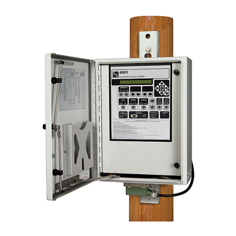
- Page 20 Installation Figure 16. Side view of the switch control enclosure on the pole. Pad-mounted controls Mount the switch control chassis in the low-voltage compartment as follows: Find the four studs on the wall of the low-voltage compartment. Position the switch control so that the four studs align with the four holes in the mounting fl...
- Page 21 Installation Ground the enclosure. Use the ground lug which is located on the bottom of the enclosure to ground the switch control. See Figure 14. The ground lug will accommodate up to #2 wire, copper or aluminum, solid or stranded. Ç...
-
Page 22: Connect The Battery
Installation Figure 19. Connection terminal for ac control power. Ç WARNING Leave the 10-ampere AC LINE fuse out until instructed to replace it later in the installation process. Leave the ac control power de-energized until you are instructed to turn it on. Connect the Battery 1. - Page 23 Installation Unscrew the black knobs and wing nuts that attach the battery bracket, and remove the bracket. If you are replacing the battery, unclip the battery connector wires from the bracket and remove the old battery. Slide the new battery onto the battery shelf, with the connector facing out and the bottom of the battery toward the left.
-
Page 24: Check Input Connections
Installation Check Input 1. For pad-mounted controls, check that the voltage and current inputs on the Connections switch interface module are configured correctly. Skip this step if the switch control was factory installed. Locate the switch interface module on the left side of the chassis. Older pad- mounted controls have the interface module on the bottom of the control chassis. -
Page 25: Add Ac Power And Test
Installation Figure 23. Switch Interface Connectors on Pad-mounted Switch Controls. Add Ac Power 1. For switch controls that use ac control power, energize the ac power. and Test 2. Check the AC ON and CHG ON LEDs. When you insert the 10-A AC Line fuse, the red AC ON and CHG ON LEDs should illuminate. - Page 26 Installation 3. Test the faceplate functions. At this point you can test most of the faceplate LEDs and switches. See Figure 24. Figure 24. S&C 6801 Faceplate. To test the LEDs and switches: Check that the PROCESSOR STATUS LED on the faceplate is blinking. If it is not blinking, see S&C Instruction Sheet 1045-550.
- Page 27 Installation Ç WARNING Scada Control must be set to LOCAL, and Automatic Operation set to DISABLED to avoid unexpected operation of the switch(es) during installation and setup of the switch control. 4. Check the connection to the switch(es). Check that the faceplate OPEN and CLOSED switch LEDs correctly indicate the actual position of the line switch(es).
-
Page 28: Check Communication Equipment
If necessary, make sure that the communications equipment has power. For overhead Equipment switch controls the communications equipment is on the back of the faceplate. For 6800 Series Switch Controls installed in pad-mounted gear, the communication equipment is not mounted inside the 6800 Series chassis. Put the Control Into Remove any temporarily-installed bypass that was applied at Step 3 on page 19. -
Page 29: Installation Drawings.)
Installation Diagrams S&C Instruction Sheet 1045-510... - Page 30 Installation Diagrams S&C Instruction Sheet 1045-510...
- Page 31 Installation Diagrams S&C Instruction Sheet 1045-510...
- Page 32 Installation Diagrams S&C Instruction Sheet 1045-510...
- Page 33 Installation Diagrams S&C Instruction Sheet 1045-510...
- Page 34 Installation Diagrams S&C Instruction Sheet 1045-510...
- Page 35 Installation Diagrams S&C Instruction Sheet 1045-510...
- Page 36 Installation Diagrams S&C Instruction Sheet 1045-510...
- Page 37 Installation Diagrams S&C Instruction Sheet 1045-510...
- Page 38 Installation Diagrams S&C Instruction Sheet 1045-510...
- Page 39 Installation Diagrams S&C Instruction Sheet 1045-510...
- Page 40 Installation Diagrams S&C Instruction Sheet 1045-510...
Need help?
Do you have a question about the 6800 Series and is the answer not in the manual?
Questions and answers