S&C 6800 Series Instruction Sheet
Automatic switch controls with intelliteam sg automatic restoration system
Hide thumbs
Also See for 6800 Series:
- Instruction sheet (44 pages) ,
- Navigation manual (17 pages) ,
- Instruction sheet (40 pages)
Table of Contents
Advertisement
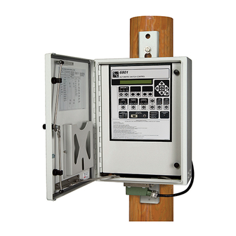
S&C 6800 Series Automatic Switch Controls with
IntelliTeam
®
SG Automatic Restoration System
Table of Contents
Section
Qualified Persons . . . . . . . . . . . . . . . . . . . . . . . . . . 2
Read this Instruction Sheet . . . . . . . . . . . . . . . . . . . 2
Retain this Instruction Sheet . . . . . . . . . . . . . . . . . . . 2
Special Warranty Provisions . . . . . . . . . . . . . . . . . . . 2
Understanding Safety-Alert Messages . . . . . . . . . . . 4
Following Safety Instructions . . . . . . . . . . . . . . . . . . 4
Replacement Instructions and Labels . . . . . . . . . . . 4
. . . . . . . . . . . . . . . . . . . . . . . . . . . 5
Applicable Software . . . . . . . . . . . . . . . . . . . . . . . . . 6
Software Overview . . . . . . . . . . . . . . . . . . . . . . . . . . 7
Computer Requirements . . . . . . . . . . . . . . . . . . . . . 7
Installing a License Activation File . . . . . . . . . . . . . . 9
Starting IntelliLink Software . . . . . . . . . . . . . . . . . . .11
Navigating IntelliLink Screens . . . . . . . . . . . . . . . . .11
IntelliLink Workspace . . . . . . . . . . . . . . . . . . . . . . . .16
Switch Control Setup
Setup General Screen . . . . . . . . . . . . . . . . . . . . . . 20
Sensor Configuration . . . . . . . . . . . . . . . . . . . . . . . 22
Site-Related Configuration . . . . . . . . . . . . . . . . . . . 25
Metering Data . . . . . . . . . . . . . . . . . . . . . . . . . . . . . 28
Fault Detection Configuration . . . . . . . . . . . . . . . . 29
Automatic Operation Configuration . . . . . . . . . . . . . . . 37
User Commands Configuration . . . . . . . . . . . . . . . 44
January 28, 2019
© S&C Electric Company 2011-2019, all rights reserved
Setup
Page
Section
Hot Line Tag . . . . . . . . . . . . . . . . . . . . . . . . . . . . . . 45
Shots to Lockout . . . . . . . . . . . . . . . . . . . . . . . . . . . 45
Time Configuration . . . . . . . . . . . . . . . . . . . . . . . . 46
Firmware Revisions . . . . . . . . . . . . . . . . . . . . . . . . 49
User Notes . . . . . . . . . . . . . . . . . . . . . . . . . . . . . . . 49
Team RTU Addresses . . . . . . . . . . . . . . . . . . . . . . 50
Team Setup . . . . . . . . . . . . . . . . . . . . . . . . . . . . . . .51
External Loading . . . . . . . . . . . . . . . . . . . . . . . . . . . 56
Team Communication Parameters . . . . . . . . . . . . 58
Distributed Generation . . . . . . . . . . . . . . . . . . . . . . 59
Restoration-External Device . . . . . . . . . . . . . . . . .61
Communications Setup . . . . . . . . . . . . . . . . . . . . . 64
Serial Ports . . . . . . . . . . . . . . . . . . . . . . . . . . . . . . . 70
Routing . . . . . . . . . . . . . . . . . . . . . . . . . . . . . . . . . .71
Ethernet Settings . . . . . . . . . . . . . . . . . . . . . . . . . . 72
Wi-Fi Settings . . . . . . . . . . . . . . . . . . . . . . . . . . . . . .74
Communication Tests . . . . . . . . . . . . . . . . . . . . . . . 75
DNP Diagnostics . . . . . . . . . . . . . . . . . . . . . . . . . . 77
DNP Status Point Mapping . . . . . . . . . . . . . . . . . . 78
DNP Double-Bit Status Point Mapping . . . . . . . . . 80
DNP Analog Input Point Mapping . . . . . . . . . . . . . . .81
DNP Control Point Mapping . . . . . . . . . . . . . . . . . . 82
DNP Analog Output Point Mapping . . . . . . . . . . . . 83
DNP Counter Point Mapping . . . . . . . . . . . . . . . . . 84
Security Settings . . . . . . . . . . . . . . . . . . . . . . . . . . 85
Log Management . . . . . . . . . . . . . . . . . . . . . . . . . . 86
Setup Validate/Apply . . . . . . . . . . . . . . . . . . . . . . . . 89
Instruction Sheet 1045-530
Page
Advertisement
Table of Contents

Related Manuals for S&C 6800 Series


Summary of Contents for S&C 6800 Series
-
Page 1: Table Of Contents
S&C 6800 Series Automatic Switch Controls with IntelliTeam ® SG Automatic Restoration System Setup Table of Contents Section Page Section Page Introduction Hot Line Tag . . . . . . . . . . . . . . . . . . . . . . . . . . . . . . 45 Qualified Persons . -
Page 2: Introduction
Special Warranty The standard warranty contained in S&C’s standard conditions of sale, as set forth in Price Sheets 150 and 181, applies to the S&C 6800 Series Automatic Switch Control, except Provisions that the first paragraph of the said warranty is replaced by the following:... - Page 3 IntelliTeam SG Automatic Restoration System until the desired result is achieved. Warranty of the S&C 6800 Series Automatic Switch Control is contingent upon the installation, configuration, and use of the control or software in accordance with S&C’s applicable instruction sheets.
-
Page 4: Safety Information
Understanding Several types of safety-alert messages may appear throughout this instruction sheet and on labels and tags attached to your S&C 6800 Series Automatic Switch Control. Safety-Alert Familiarize yourself with these types of messages and the importance of these various... -
Page 5: Safety Precautions
Safety Precautions DANGER The S&C 6800 Series Automatic Switch Control line voltage input range is 93 to 276 Vac. Failure to observe the precautions below will result in serious personal injury or death. Some of these precautions may differ from your company’s operating procedures and rules . -
Page 6: Intellilink® Setup Software
. The S&C 6800 Series Automatic Switch Control is connected to switchgear operating at primary voltage levels . High voltage may be present in the wiring to the switch control or in the switch control itself during certain failures of the switchgear wiring or grounding system, or because of a failure of the switch itself . -
Page 7: Software Overview
Setup Software ® Software Overview The software installer for 6800 Series controls is similar to the installers for other IntelliTeam SG system-capable products. The overview section in Instruction Sheet 766-571, “IntelliRupter® PulseCloser® Fault Interrupter: Software Installation,” will provide useful information about the software installer. -
Page 8: Intellilink® Setup Software License Activation
Setup Software ® The latest 6800 Series control software release is posted at the S&C Automation Customer Support Portal. This library of current, and legacy software requires a password to provide users access to the software needed for S&C equipment oper- ated by their utility. -
Page 9: Installing A License Activation File
IntelliLink Setup Software ® Figure 2. IntelliTeam SG Software workspace on the S&C Automation Customer Support Portal. The next step is to download and save the license-activation file, “ActivationFile. xml,” as directed in the “Installing a License Activation File” section below. When an email notification that the activation file is ready has been received, log in to the S&C Automation Customer Support Portal account and follow the steps below. - Page 10 IntelliLink Setup Software ® For Windows XP: Follow these steps to save the ActivationFile.xml file: On the Tools tab, select the Folder options... entry. See Figure 3. STEP 1. Figure 3. The Windows File Explore Tools>Folder options. STEP 2. On the View tab, select the radio button for the Show hidden files, folders, and drives entry.
-
Page 11: Starting Intellilink Software
To edit a snapshot (virtual memory file) or Software simply view the software without data, see the “Using Snapshots” section in Instruction Sheet 1045-540, “S&C 6800 Series Automatic Switch Controls: Operation.” NOTICE When using an ungrounded (two-wire) extension cord to power either the computer or the switch control while they are connected, the serial port on the computer may be damaged . - Page 12 ® Figure 5. The Operation screen for a 6801 Automatic Switch Control. The Operation screen presents 6800 Series Control status information and can issue operation commands. User-assigned location-identification information (Connected to: and Location:) is shown at the top of every screen. See Figure 5.
- Page 13 IntelliLink Setup Software ® Automatic Operation This setting enables or disables Automatic Operation mode. Automatic Restoration This setting enables or prohibits Automatic Restoration mode. Remote Communications These indicators show communication activity. Error Detected Perform Diagnostics This indicates an active error condition. Processor Status Blinking = OK This displays the processor heartbeat, and blinking indicates proper operation.
- Page 14 IntelliLink Setup Software ® This is only displayed on the IntelliLink software Operation screen; there is no CLOSED-LOOP BREAK SWITCH LED on the faceplate. The faceplate displays the active Shots to Lockout mode by blinking the SWITCH CLOSED LED, and on the LCD screen under the “Maintenance”...
- Page 15 IntelliLink Setup Software ® Control Status Message This can indicate: OKAY—The control is operating correctly. Settings Mismatch—The Validate/Apply command failed. Problem Present—An error has been detected that is not a Warning or Alarm condition. Switch 1/2 Auto Operation Status SCADA commands can enable/disable the Automatic Operation mode for each switch. This indicates a Disabled state for both switches when the Automatic Operation mode has been disabled on the Operation screen or the faceplate.
-
Page 16: Intellilink Workspace
IntelliLink Workspace The IntelliLink software user interface includes many standard features found in Windows-based products as well as some custom features designed to make navigating through the 6800 Series Switch Control settings easier. See Figure 6. Tool bar Status bar... - Page 17 IntelliLink Setup Software ® Same as the Validate button on the Setup> Validate/Apply screen. See Figure 42 on page 84. Validate Checks the pending changes but does not apply them. Same as the Apply button on the Setup>Validate/ Apply screen. See Figure 42 on page 84. Checks Apply the pending changes and applies them if no errors are found.
- Page 18 IntelliLink Setup Software ® Navigation Tree Indicates the item to the right is collapsed w it h add it iona l items u nder neat h. Expand Arrow Clicking this icon expands the list to show the hidden sub-items. Indicates the item to the right is expanded, showing additional items underneath.
- Page 19 IntelliLink Setup Software ® Communication Status The communication status bar at the bottom of the IntelliLink software screen displays the connection addresses, the refresh mode, and the last refresh. The time changing after “Refresh:” indicates the control is communicating. The refresh defaults to the Auto setting, but it can be stopped by clicking on the Stop button and manually refreshed by clicking on the Once button that comes into context when the refresh is stopped.
-
Page 20: Setup General Screen
Switch Control Setup Setup General Screen Figure 7. The Setup>General>SG6800 screen. Logging Level This setting configures the data log message types displayed on the Logs/Historic Events screen. Possible settings are Normal, Extended, and All. See Figure 7. Duplicate Event Margin (milliseconds) The storage of identical events within a short time period can flood the internal memory and does not yield useful diagnostic information. - Page 21 Switch Control Setup Device Serial Number The serial number is automatically read from the control. Cabinet Heater On 100% Below This Temperature If there is a heater in the switch control enclosure and the control is powered by an external ac source, the heater stays on continuously while the interior enclosure temperature is below this value.
-
Page 22: Sensor Configuration
Switch Control Setup Sensor Configuration Figure 8. The Setup>General>Sensor Configuration screen (6801 switch control shown). This screen allows entering calibration data for S&C Scada-Mate® Switching Systems; automated Omni-Rupter® Switches; and PME, PMH, or Vista Underground Distribution Switchgear sensors. See Figure 8. The switch control uses this data to calibrate sensor input to the voltage and current amplitude accuracy specified for S&C sensors. - Page 23 When a switch control has the sensor-power option, this setpoint is factory set to the Present state. A 6800 Series control with the sensor-power option has a cable connected from J8 on the PS/IO (Power Supply/Input Output) board to J6 on the SPA (Sensor Power Analog) board.
- Page 24 Switch Control Setup Fault-Interrupter Option (only applicable to Vista switches) When the Vista Underground Distribution Switchgear includes fault-interrupting positions, select the Present state. When a fault interrupter trips open, the OVERCURRENT FAULT indicator flashes, the LCD displays a message, and the switch control makes entries on the Diagnostics>Fault Info and Logs>Status Point Log screens.
-
Page 25: Site-Related Configuration
Qualification Time setting on the Setup>General>Automatic Operation screen. For more information about voltage-loss detection qualification time characteristics, see the “Loss of Voltage Threshold” section in S&C Instruction Sheet 1045-530, “S&C 6800 Series Automatic Switch Controls with IntelliTeam® SG Automatic Restoration system: Setup.”... - Page 26 Switch Control Setup Figure 10. The Voltage Loss Threshold and Maximum Response Time curve. NOTICE Times listed in the Figure 10 curve do not include the output relay or switch operation times . For proper coordination with a fast reclosing source-side protective device, make sure the reclosing interval time for the device is long enough for the switch control to detect the outage and for the sectionalizing switch to open fully .
- Page 27 Switch Control Setup Reverse Current Time Threshold (seconds) This is the minimum qualification time a change in current direction must persist after detection before it is displayed or reported. The default is 10 seconds. This setting was not previously configurable. Set this value to the Disabled mode to stop reporting the change of current direction, and any present indication of a reverse current condition will be cleared.
-
Page 28: Metering Data
Switch Control Setup Metering Data Figure 11. The Metering screen for a 6802 switch control. All values are time-averaged and reported locally and via SCADA on a one-second interval. See Figure 11. Primary Metering Data Current The current sensor output is scaled according to the calibration factors entered on the Setup>General>Sensor Config screen. -
Page 29: Fault Detection Configuration
Switch Control Setup Fault Detection Configuration Figure 12. The Setup>General>Fault Detection screen. This screen allows entering setpoint values the switch control will use to detect phase and ground faults. See Figure 12. It includes the following fields: Phase and Ground Overcurrent Detection Parameters Phase fault current is measured by a high-speed detecting circuit that has a full scale of approximately 4200 amps RMS and samples every 6.25 ms. - Page 30 Switch Control Setup Figure 13. The TCC curve for ground fault detection. Phase Overcurrent Detection Setup Procedure To determine the proper setting, we need to look at the source-side protective device phase TCC curves for a range of fault duty, up to the maximum available phase fault current at the sectionalizing switch.
- Page 31 Switch Control Setup Figure 14. The coordination sheet for phase overcurrent and inrush. S&C Instruction Sheet 1045-530...
- Page 32 Switch Control Setup Ground Overcurrent Detection Setup Procedure To determine the proper setting, look at the source-side protective device’s ground TCC curves for a range of fault duty, up to the maximum available ground fault current at the sectionalizing switch. The switch control must be able to detect the fault before the source-side protective device trips.
- Page 33 Switch Control Setup an Inrush Restraint Numerical Multiplier setpoint (of 2x, 4x, etc.) and the elevated Ground Fault Detection Current Level value exceeds the maximum-available ground short-circuit current level, adjust the Ground Fault Duration Time Threshold and Ground Fault Current Inrush Restraint Time setpoints to ensure the switch control has enough time after the restraint time to detect a ground fault.
- Page 34 3x full load for 10 seconds, and 2x full load for 100 to 300 seconds. The 6800 Series switch control invokes inrush restraint whenever three-phase voltage is lost and one or more phases return. The current inrush restraint time is the amount of time, in milliseconds, that must elapse after restoration of voltage before the switch control will respond normally to an overcurrent fault condition.
- Page 35 Switch Control Setup Phase Current Inrush Restraint Time (Milliseconds) Set this setpoint to a value long enough to allow the inrush/load pickup current to drop below the Phase Fault Detection Current Level setpoint before the timer expires. (Range: 0.00-1,593.75; Step: 6.25; Default: 75.00) Phase Current Inrush Restraint Multiplier Select either the Time Block or a Multiplier Value setting.
- Page 36 Switch Control Setup Time Block—Ground (unbalanced) currents are not qualified until the restraint timer expires. Adjust the Ground Fault Duration Time Threshold and Ground Current Inrush Restraint Time setpoints to ensure the switch control has enough time after the time block to detect a ground fault before the feeder breaker operates again. Multiplier Value—The Ground Fault Detection Current Level is temporarily raised by the selected multiplier value: 2x, 4x, 8x, or 16x.
-
Page 37: Automatic Operation Configuration
Switch Control Setup an IntelliLink software command, by issuing a Clear Fault command through the LCD faceplate menu, or by using a USER ASSIGNED button mapped to the Clear Faults command. Reset When Fault Clears With this strategy selected and the Overcurrent Fault indicator active, it will reset automatically when all of these conditions are met: •... - Page 38 Switch Control Setup Phase Loss Protection—Team members open their switch based on loss of voltage on one or two individual phases. Important: If one of the automatic operation options is selected (on either switch if applicable), use the faceplate AUTOMATIC OPERATION ENABLE/DISABLE switch or a SCADA command to disable automatic operation.
- Page 39 Switch Control Setup the control resets the sectionalizing timers and counters to zero. Configure this setpoint if the Successful Reclose Reset Time setting has been implemented in the source-side protective device. Set the value to the same value as the source-side protective device.
- Page 40 Switch Control Setup The time selected for the next breaker operation after the instant reclose must be longer than the time chosen for the First Reclose Qualification Time setting by 250 ms to allow the subsequent operation to qualify as the first recloser operation count. Therefore, for reliable operation, the First Reclose Qualification Time setting MUST be set to a value that is at least 250 ms shorter than the next breaker operation.
- Page 41 Switch Control Setup Recloser Counts to Sectionalizer Trip, Voltage Loss Only When sectionalizing is enabled, the 3-Phase Volt Loss Sectionalizing feature is set to the Yes or ITSG Only mode, the IntelliTeam system is in the Ready state, and the switch control detects this number of three-phase voltage losses with no fault current, the control opens the line switch.
- Page 42 Switch Control Setup Figure 18. The Setup>General>Automatic Operation screen, with Three-Phase Volt Loss Sectionalizing, Phase Loss Protection, and Automatic Reclose expanded. 3-Phase Volt Loss Sectionalizing This feature is only applicable when the Sectionalizing mode is set to the Yes setting. See Figure 18.
- Page 43 Switch Control Setup In a wye system, when a phase loses voltage, the voltage reading is 0 (zero) for that phase, so a phase imbalance can be detected easily. In a delta system, the loss of one phase results in sensor readings with magnitudes slightly more than half of the normal phase-to-phase voltage.
-
Page 44: User Commands Configuration
Switch Control Setup User Commands Configuration Figure 19. The Setup>General>User Commands screen. This screen defines the user labels for user-assignable commands and their assignment to the two User Select buttons on the Operation screen. See Figure 19. Enter text for the command label of each command function. -
Page 45: Hot Line Tag
Switch Control Setup Line 2 Label This is the second text line for the user to add descriptive information about the switch location. Hot Line Tag An active Hot Line Tag (HLT) mode inhibits closing by: a front panel switch command, a SCADA command, a remote IntelliLink Setup Software command, or automatically by the IntelliTeam SG Automatic Restoration System. -
Page 46: Time Configuration
Switch Control Setup CAUTION It is very important to properly coordinate the end of the Shots-to-Lockout timer with the source breaker operation . Operation of the breaker at the same time the switch opens could result in a switch malfunction . To enable the Shots to Lockout mode on an open switch from the front panel, the SCADA Control function indication must be in Local mode. - Page 47 Switch Control Setup When SCADA mode is selected, the real-time clock will be synchronized to the time and date specified in the SCADA master’s time synchronization request. Configuration of the Time Sync Request Interval setting is required. When GPS and SCADA mode is selected, the GPS signal will be used when avail- able.
- Page 48 Switch Control Setup • Manual input mode • Simulation mode Horizontal Dilution of Precision of GPS Fix This statement indicates the relative estimate of GPS horizontal position fix accuracy: <1 = Ideal—This is the highest confidence level. 1-2 = Excellent—The position measurements are accurate for most applications. 2-5 = Good—This is the minimum information appropriate for making business decisions.
-
Page 49: Firmware Revisions
IntelliLink software, and the installed version is loaded from the connected control. The latest 6800 Series Automatic Switch Control software revisions are available at the S&C Automation Customer Support Portal, which requires an assigned user name and password. -
Page 50: Team Rtu Addresses
Switch Control Setup Team RTU Addresses Figure 23. The Setup>Restoration>IntelliTeam SG>Team Summary screen. The screen shown in Figure 23 shows the DNP/RTU address of the teams in which this control is a member and shows Ready status for each team. DNP Addresses and Team Status Team Selection The tabs for Team 1 through Team 8 can be used to navigate to screens where general... -
Page 51: Team Setup
Switch Control Setup When the No option is selected, the IntelliTeam application functions normally. The application will qualify a fault condition and determine fault location based on the exter- nal device DNP status point information. Source Transfers with Bus Sensing (only for 68023PM software) A source-transfer switch with voltage sensing on the bus cannot sense voltage present when the primary source is lost. - Page 52 Switch Control Setup Important: For any one team, the values must be identical in all team members except for the Comm Port to Use setting. Each team screen includes the following fields: Team ID Enter the name of this team, 16 characters maximum. This name will help identify the team to the SCADA operator.
- Page 53 Switch Control Setup Priority3_OpenXfer—Load shedding is not allowed. Load transfer allowed through an open transition only. Priority4_XferShed—Load shedding is allowed. Only shed after transfers to other circuits have been considered. Priority 4 is the highest priority of this category. Priority5_XferShed—Load shedding is allowed. Only shed after transfers to other circuits have been considered.
- Page 54 SCADA command or clicking on the IntelliTeam SG Restoration Enabled button on the IntelliTeam SG>Team Summary screen. For 6800 Series Controls and 6801M Switch Operators, the AUTOMATIC RESTORATION Enabled command on the faceplate or Operation screen can also be used.
- Page 55 Switch Control Setup Load/Tie A team may have from zero to seven closed switches through which loads on other line segments receive power. This value is assigned when the switch could be involved in restoring power to the line segment because line segments on the other side of the switch have alternate sources.
-
Page 56: External Loading
Switch Control Setup External Loading Figure 25. The Setup>Restoration>IntelliTeam SG>External Loading screen. The screen in Figure 25 is used with feeder loading monitored at the substation breaker to calculate the real-time excess capacity available when a transfer occurs. Both Maximum Source Capacity and Default Source Segment Loading settings must only be set for SRC/sub or tie/sub. - Page 57 Switch Control Setup This setting is configured in the IntelliTeam Designer software and cannot be changed on this screen. See S&C Instruction Sheet 1044-570, “S&C IntelliTeam® Designer: User’s Guide.” For example: If the Maximum Source Capacity value is set to 150 amps and the Overload Permitted value is set to 150 amps, the PRLM will allow up to 300 amps of load on that source before shedding load.
-
Page 58: Team Communication Parameters
Switch Control Setup STATUS: Source Loading Data If either the Maximum Source Capacity or the Default Source Segment Loading setpoint is not configured, the real-time loading feature is not active. This field will show “Disabled,” even if the team member receives feeder-loading data. In this case, the present calculations using the Maximum Source Capacity value are used. -
Page 59: Distributed Generation
Switch Control Setup Netlist Verbose Logging When enabled, all Netlist-related event messages will be logged. The default is the Disabled setting because Netlist logging quickly fills log memory and should only be used for troubleshooting a specific situation. IntelliTeam Verbose Logging When enabled, all IntelliTeam restoration system event messages (excluding Netlist- related events) will be logged. - Page 60 Switch Control Setup Default DG Load Contribution This setting should only be used when no real-time loading data are available from a distributed generation device. When set to a non-zero value, the IntelliTeam system uses this as the amount of current flowing from the distributed generation device into the distributed generation team.
-
Page 61: Restoration-External Device
Switch Control Setup Restoration—External Device Figure 28. The Setup>Restoration>External Device screen. Remote Prohibit Restoration List Section This screen contains setpoints specifically related to sending the Prohibit Restoration SCADA command to remote devices. The non-zero RTU address in this list must be configured to receive a Latch On, Direct Operate SCADA control point when any of the following events are active in the control: Hot Line Tag mode is active, the IntelliTeam SG system determines that a Manual Operation event has occurred or a SCADA Prohibit... - Page 62 Switch Control Setup Retry Timer Enter the amount of time in seconds to wait before a retry is attempted. (Range: 0-255; Step: 1; Default: 5) Control Point Number Enter the DNP control point number that activates the Prohibit Restoration mode in the remote device.
- Page 63 Switch Control Setup Device This is the Device ID for the remote device. RTU Address Enter the address of the remote device. (Range: 0-65519; Step: 1; Default: Not Configured) Port Code Select the port to use for transmitting to the remote device. (Default: UDP) IP Address When the Port Code is set to “UDP,”...
-
Page 64: Communications Setup
Switch Control Setup Remote Transfer Trip Selecting the Enabled state allows commands from this device to be sent to all non- zero RTU addresses listed on the Remote Transfer Trip List. Selecting the Disabled state blocks the commands. When there are no distributed generation resources listed on the Remote Transfer Trip List, set this to the Disabled state. - Page 65 Switch Control Setup NOTICE Changing the DNP address or other communication parameter can prevent the control from communicating with other team members in an IntelliTeam SG system, and via SCADA or a remote IntelliLink software connection . If communication is lost with a control, go to the site, connect through IntelliLink soft- ware, and reset the communication parameter that had been changed .
- Page 66 Switch Control Setup Use of Self-Address 65532 NOTICE Disabling the Use of Self-Address setting can prevent the control from communicating with IntelliLink software . If communication with the control is lost, you must know the Local Device DNP Address setting, connect through a remote IntelliLink software connection, and re-enable the Use of Self-Address setting to connect locally .
- Page 67 Switch Control Setup DNP Application Layer Confirmations When the Enabled setting is selected, an application layer confirmation will be requested with every solicited response that includes event data. Event buffers will not be cleared until an application layer confirmation is received from the master station. When disabled, the event buffers are cleared when events are reported.
- Page 68 Switch Control Setup DNP Counter Type (not applicable for IntelliRupter fault interrupters) Selects the counter that will be reported in static data for a Class 0 Poll requested by the master station. Selections are “Frozen,” “Running,” and “Both Counters;” the default is “Both Counters.”...
- Page 69 Switch Control Setup Entering an IP Address IP address entry has been simplified, follow these steps: Click and highlight the character in the first cell. STEP 1. Type one to three characters as needed. STEP 2. STEP 3. Hit the space bar to advance to the next field. Advancing in this fashion automatically highlights the characters in the next field.
-
Page 70: Serial Ports
Restoration System, SCADA, and IntelliLink Setup Software. See Figure 30. S&C automation products have different serial-ports configurations: • IntelliRupter fault interrupters have only one serial port • 6800 Series Controls have configurable serial ports A and B • IntelliNode Interface Modules have four configurable serial ports Communication Protocol DNP is permanently configured because S&C controls only use the Distributed Network... -
Page 71: Routing
Switch Control Setup RTS Active Before/Following Xmit This is the time, in milliseconds, the request to send (RTS) is active for this port before and after a transmission takes place. The default value is usually suitable. Interpacket Delay This is the time in milliseconds, between individual message frames of a data stream. Set this parameter appropriately for the radio. -
Page 72: Ethernet Settings
Switch Control Setup Port This parameter should be configured if the intended destination device may be found through a serial communications port. This will cause the received frame to be transmitted out the configured local serial port. Ethernet Settings Figure 32. The Setup>Communications>Ethernet screen. IntelliRupter fault interrupters have only an AddOn port. - Page 73 Switch Control Setup Auto-Negotiate Enable the Auto-Negotiation setting for the Ethernet port. When disabled, the Duplex Mode setting and Data Rate setting must be configured. NOTICE The Native Port of units shipped before April 17, 2014, do not support the Auto-Negotiate function .
-
Page 74: Wi-Fi Settings
Switch Control Setup Wi-Fi Settings Figure 33. The Setup>Communications>Wi-Fi screen. The Wi-Fi module is a separate computer that sends Wi-Fi communication information to the MCU computer in the control over a serial port. The Wi-Fi module must have the control serial number registered to initiate Wi-Fi communication with a PC at the site. When the Wi-Fi module cannot obtain a serial number from the control, it uses the universal serial number: 00-0000000. -
Page 75: Communication Tests
Switch Control Setup Keepalive Status The Wi-Fi module exchanges a message with the control every 5 seconds. When the control responds, the Wi-Fi module maintains communication and reports “Keepalive Active.” Flash Memory Access Status “Wi-Fi Signature Record obtained” indicates that the Wi-Fi module obtained the required configuration information from flash memory, such as the security passwords. - Page 76 Switch Control Setup Test By The test duration mode can be selected: By Time—the amount of time it will run, or By Message—the total number of messages it will send. (Default: By Time) Time Duration When the Test By Time option is selected, the Time Duration field sets the number of hours the test will be run.
-
Page 77: Dnp Diagnostics
Switch Control Setup Predefined Data Types The Connection ID in Row 0 is always configured “Coach” and Row 1 is always configured “Runner.” The Bytes Sent and Bytes Received fields are not configurable. Definable Data Types The Connection IDs in Row 2 and 3 are always configured “Undefined” whereas the Bytes Sent and Bytes Received fields are user defined. -
Page 78: Dnp Status Point Mapping
Switch Control Setup Good Link Health Threshold This configures the percentage of successful message transmissions that will define good link health. (Range: 85-99; Step: 1; Default: 95) Marginal Link Health Threshold This configures the percentage of successful message transmissions that will define marginal link health. - Page 79 Switch Control Setup Code-Description These are the point codes representing specific status points that may be assigned to individual SCADA point numbers. Setting a Code-Description point code to the “End” setting defines the end of the configured points list and the maximum number of status points that can be returned.
-
Page 80: Dnp Double-Bit Status Point Mapping
Switch Control Setup When the Require SCADA Acknowledgement setpoint is set to Yes, the User Command section of the LCD screen includes an option to clear each of the configured user-defined inputs. (Press ENTER to run command: Clear User Input n) Common Input 1 Input 2... -
Page 81: Dnp Analog Input Point Mapping
Switch Control Setup Class This is the DNP event class in which this point can be placed. Specify Class 1, Class 2, Class 3, or choose the No Event option if event data reporting is turned off for this point. DNP Analog Input Point Mapping Figure 39. -
Page 82: Dnp Control Point Mapping
Switch Control Setup Pct DeadBand This is the deadband range expressed as a percentage of the previously reported analog input data. If the analog input data associated with this point exceed the range in either a positive or negative direction, the information will be included in the next event report. Specify the N/A option to turn off deadband reporting as a percentage of the previously reported analog input data. -
Page 83: Dnp Analog Output Point Mapping
The object type must be valid for the selected object. For more information see the appropriate Instruction Sheet 1045-560, 1045-560B, 1045-560C, 1045-560D, 1045- 560E or 1045-560F: “S&C 6800 Series Automatic Switch Controls: DNP Points List and Implementation.” The control operation will be rejected if the object type received is Pulse and the mapped object type is either Breaker or Latch, or if the mapped object type is Pulse and the received object type is either Breaker or Latch. -
Page 84: Dnp Counter Point Mapping
Switch Control Setup DNP Counter Point Mapping Figure 42. The Setup>Point Mapping>Counter Point Mapping screen. The screen shown in Figure 42 contains configuration parameters for Counter points. Map these points to make them available in the SCADA system. Counter Point This is the point number the SCADA system will use in response to a static or event data request or an unsolicited event response. -
Page 85: Security Settings
1. IntelliTeam SG Restoration—on the IntelliTeam SG>Team Summary screen Clear Manual Operation—on the IntelliTeam SG>Team Summary screen For 6800 Series Automatic Switch Controls, these commands are not available when this setting is set to Disabled mode: 1. Switch Open—on the Operation screen 2. -
Page 86: Log Management
Switch Control Setup Log Management Figure 44. The Setup>Logs>Log Management screen. The screen shown in Figure 44 configures the filter settings for viewing log screens. The Administrative login is required to execute any of the log-control functions. Logging Settings Logging Level The logging level selected determines the type of data-log messages captured in the base memory module (for an IntelliRupter fault interrupter) and is displayed on the Logs>Historic Log screen. - Page 87 Switch Control Setup Compact Flash Logging When enabled, every historic event generated is written to flash memory. Logging Level and Duplicate Event Margin setpoints do not prevent an event from being written to flash memory. Flash memory logging preserves as much data as possible. Flash memory data can be retrieved with IntelliLink software.
- Page 88 Switch Control Setup Chronological Browsing (static – no refill) Chronological browsing is only available in the Static View mode. It is not available in the Real Time View mode. Because the size of the Logs>Historic Log screen is only a fraction of that of the Historic Event Log, the Historic Event Log must be navigated chronologically, either by Browse By Time mode or Browse By Page mode.
-
Page 89: Setup Validate/Apply
If a Validation or Apply command is unsuccessful, the Validation Result field will provide information related to the violated validation rules. Command Status Shows the result of the last Validation or Apply request. This completes 6800 Series Switch Control setup. S&C Instruction Sheet 1045-530...
Need help?
Do you have a question about the 6800 Series and is the answer not in the manual?
Questions and answers