S&C BankGuard PLUS Troubleshooting Instructions
Hide thumbs
Also See for BankGuard PLUS:
- Setup instructions (50 pages) ,
- Operation instructions manual (28 pages) ,
- Installation manual (24 pages)
Table of Contents
Advertisement
Quick Links
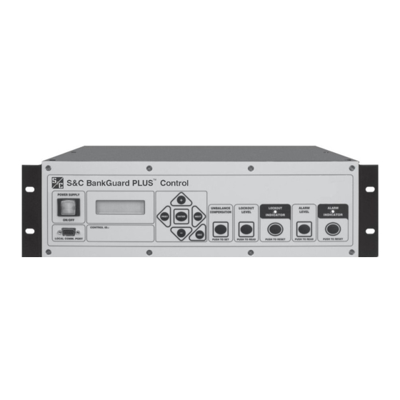
S&C BankGuard PLUS™ Control
TABLE OF CONTENTS
Section
Qualified Persons . . . . . . . . . . . . . . . . . . . . . . . . . . . . . . . 2
Read this Instruction Sheet . . . . . . . . . . . . . . . . . . . . . . . 2
Retain this Instruction Sheet. . . . . . . . . . . . . . . . . . . . . . 2
Warranty . . . . . . . . . . . . . . . . . . . . . . . . . . . . . . . . . . . . . . 2
Latest Document Release . . . . . . . . . . . . . . . . . . . . . . . . 2
Understanding Safety-Alert Messages . . . . . . . . . . . . . . 3
Following Safety Instructions . . . . . . . . . . . . . . . . . . . . . 3
Replacement Instructions and Labels . . . . . . . . . . . . . . 3
S&C ELECTRIC COMPANY
Specialists in Electric Power Switching and Protection
Troubleshooting Instructions
Page
Section
Applicable Software . . . . . . . . . . . . . . . . . . . . . . . . . . . . .5
Overview . . . . . . . . . . . . . . . . . . . . . . . . . . . . . . . . . . . . . .5
Quick Reference Guide . . . . . . . . . . . . . . . . . . . . . . . . . .7
Power Problems . . . . . . . . . . . . . . . . . . . . . . . . . . . . . . . .8
LCD and LED Problems . . . . . . . . . . . . . . . . . . . . . . . . . .8
Error Messages . . . . . . . . . . . . . . . . . . . . . . . . . . . . . . . . .9
Incorrect Real-Time Data . . . . . . . . . . . . . . . . . . . . . . . .10
Miscellaneous Problems . . . . . . . . . . . . . . . . . . . . . . . .10
Operation Information . . . . . . . . . . . . . . . . . . . . . . . . . .12
Product Information . . . . . . . . . . . . . . . . . . . . . . . . . . . .15
Chronological Log . . . . . . . . . . . . . . . . . . . . . . . . . . . . . .16
Page
Instruction Sheet 1011-550
©
October 22, 2007
2007
Supersedes 1011-550 dated 2-13-06
Advertisement
Table of Contents

Related Manuals for S&C BankGuard PLUS


Summary of Contents for S&C BankGuard PLUS
-
Page 1: Table Of Contents
S&C BankGuard PLUS™ Control Troubleshooting Instructions TABLE OF CONTENTS Section Page Section Page INTRODUCTION TROUBLESHOOTING Qualified Persons ....... 2 Applicable Software . -
Page 2: Introduction
INTRODUCTION Qualified Persons WARNING The equipment covered by this publication must be installed, operated, and main- tained by qualified persons who are knowledgeable in the installation, operation, and maintenance of overhead electric power distribution equipment along with the asso- ciated hazards. A qualified person is one who is trained and competent in: •... -
Page 3: Safety Information
SAFETY INFORMATION Understanding There are several types of safety-alert messages which may appear throughout this instruction sheet as well as on labels attached to the IntelliTEAM II Interface Module. Safety-Alert Familiarize yourself with these types of messages and the importance of the various Messages signal words, as explained below. - Page 4 1011-550...
-
Page 5: Troubleshooting
(high) volt- age. Overview All the following tools and BankGuard PLUS features are used to diagnose and correct BankGuard PLUS problems. The LCD on the BankGuard PLUS faceplate provides information about the present state of the control. - Page 6 Hardware Tools To correct a problem, you may need one or more of the following tools: • Multi meter • 4" long, #2 Phillips screwdriver • 4" long, 1/4"-blade screwdriver NOTICE If the suggested troubleshooting steps do not resolve the problem, call S&C Electric Company at (510) 864-6850.
-
Page 7: Quick Reference Guide
Quick Reference Guide 1011-550... -
Page 8: Power Problems
POWER SUPPLY ON/OFF button is not illuminated Power Problems Check for AC power to the control device. Following utility-approved work proce- dures and safety practices, verify that there is 120 VAC in the line which provides AC power to the control device. LCD is blank LCD and LED Problems... -
Page 9: Error Messages
S&C controls. The installation diskettes are used to install the IntelliLINK program on your PC computer along with files that are unique to the type of control they are supplied with (BankGuard PLUS™ Control Device, Intelli- CAP® Capacitor Control, etc.). Therefore, the installation diskettes for each type of control that you use should be installed on your computer. -
Page 10: Incorrect Real-Time Data
“Program in the control: XXXX... not configured for this program” Reinstall the IntelliLINK software on your computer. Make sure that you are installing the software for this type of control device. (See To Install the IntelliLINK Software in the Setup Instruction Sheet 1011-530 for details.) “Software in control incompatible with open screenset... - Page 11 buttons. Pressing the faceplate ESC button returns the LCD to the [N-G Voltage]. (For more details, see the Setup Instruction Sheet 1011-530.) UNBALANCE COMPENSATION button Pressing the UNBALANCE COMENSATION button displays the following (in order): • A newly calculated unbalance compensation magnitude value •...
-
Page 12: Using Intellilink To Locate Problems
Using IntelliLINK to Locate Problems The IntelliLINK software Operation and Product Information screens can help you check the status of the control device and locate the causes for several types of prob- lems. Operation The IntelliLINK software Operation screen (Figure 1) displays the present status of the control device setpoint values and line-to-ground voltages. - Page 13 Alarm Indicator LED and button If this “LED” is ON, the control device has set a voltage alarm the bank/reactor (based on the “Alarm Level” and “Alarm Time Delay” setpoints). To clear the LED and the alarm, click the ALARM INDICATOR RESET button. Click OK. NOTE: If the conditions that led to the alarm are still present, the control device will set the alarm again after the “Alarm Time Delay”...
- Page 14 Alarm Time Delay This is the amount of time (in seconds) that the neutral-to-ground voltage must exceed the “Alarm Level” before the control device issues an alarm. Gross Overvoltage Level This is the voltage level or tap-point voltage percent imbalance considered a gross overvoltage.
-
Page 15: Product Information
Password When this field displays a 4-digit password, the control device requires a password to make changes from the faceplate. Location This is the location of the control device. This information (up to 100 characters) may help identify the control device to the SCADA master station operator and appears on all reports generated from the control device. -
Page 16: Chronological Log
This screen includes the following fields: Setup Disk Revision, Control Software Revision Please have this information available when you call S&C Electric Company about a problem. These fields include: • The S&C name and revision date for the IntelliLINK software version that is pres- ently loaded into memory on your computer.
Need help?
Do you have a question about the BankGuard PLUS and is the answer not in the manual?
Questions and answers