S&C BankGuard PLUS Operation Instructions Manual
Hide thumbs
Also See for BankGuard PLUS:
- Setup instructions (50 pages) ,
- Installation manual (24 pages) ,
- Operation (19 pages)

Related Manuals for S&C BankGuard PLUS


Summary of Contents for S&C BankGuard PLUS
- Page 1 BankGuard PLUS™ Control Operation Instructions S&C Electric Company 6601 North Ridge Blvd. Chicago, Illinois 60626 USA 1011-540 5-17-04...
- Page 2 Installation BankGuard PLUS Control. 1011-530 describes how to use the Setup software to Setup configure the BankGuard PLUS Control, check the present settings, and view real-time data. 1011-540 describes how to view historical data, how Operations to generate reports, and how to update the Control software.
- Page 3 S&C BankGuard PLUS Control. Familiarize yourself with “SAFETY INFORMATION” on pages 3 through 5. Retain this Instruction Sheet This instruction sheet is a permanent part of your BankGuard PLUS Control. Designate a location where you can easily retrieve and refer to this publication. Warranty The standard warranty contained in S&C’s standard conditions of sale, as set forth in Price...
-
Page 4: Table Of Contents
S&C Electric Canada Ltd. at (416) 249-9171.) NOTICE Thoroughly and carefully read this instruction sheet before programming and operating your S&C BankGuard PLUS Control. Replacement Instructions and Labels If you need additional copies of this instruction sheet, contact your nearest S&C Sales Office, S&C Headquarters, or S&C Electric Canada Ltd. -
Page 5: Introduction
S&C Electric Company BankGuard PLUS Proprietary Information Control Introduction This instruction sheet provides information related to daily operation of the BankGuard PLUS Automatic Control Device, including: Control device hardware and software components (page 6) Control device features (page 9) Generating reports (page 21) -
Page 6: Control Device Hardware And Software
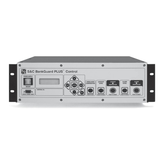
Figure 1 shows hardware components of the control device that you may need to access during regular operation and troubleshooting. The BankGuard PLUS faceplate includes LEDs and buttons which allow you to monitor the capacitor bank/reactor and the control device. It also includes a liquid crystal display and buttons for scrolling and selecting data. -
Page 7: Intellilink Software
S&C Electric Company BankGuard PLUS Proprietary Information Control Control Device Software S&C controls and devices are entirely software-driven. Each control device is shipped ® with Control Device software and IntelliLINK software. Control Device Software The Control Device software is preloaded into the control device in the factory. This software manages the minute-by-minute functioning of the control device. -
Page 8: Scada Communications Equipment
Most types of communications equipment can be mounted near the control device. This eliminates clutter and provides a higher level of reliability for the overall installation. DNP 3.0 is the standard protocol for the BAnkGuard PLUS control device; other protocol options are also available. -
Page 9: Control Device Operations
When a developing turn-to-turn fault occurs in any phase winding, the ungrounded, wye- connected shunt reactor is protected from further damage by automatic switching initiated by the S&C BankGuard PLUS Automatic Control Device. The control device isolates and locks out the entire shunt reactor when a predetermined neutral-to-ground voltage is exceeded. -
Page 10: Automatic Control Features
Capacitor Unit Power Frequency Overvoltage versus Time (IEEE Standard 18-1992) Automatic Control Features The BankGuard PLUS control device includes all the automatic features described in this section. Bank/Reactor Lockout and Alarm The lockout logic includes a user-selectable time delay (0.2 to 30 second). The time delay insures that the fuse for the failing capacitor unit operates before the control device locks out the bank. -
Page 11: Ungrounded And Grounded Wye Shunt Capacitor Banks
If desired, the alarm function can respond to loss of control power to the BankGuard PLUS control device and set an alarm. Alarms and lockouts are latched, and maintained across a software reset. They remain active until the ALARM INDICATOR RESET button or a SCADA command resets them. - Page 12 50% of the value of the neutral-to-ground voltage calculated for one isolated capacitor unit. Figure 3 System Diagram of BankGuard PLUS Control Device for Ungrounded Wye-connected Capacitor Banks Figure 4 System Diagram of BankGuard PLUS Control Device...
- Page 13 S&C Electric Company BankGuard PLUS Proprietary Information Control For ungrounded wye banks, the control device uses an analog input and digital voltmeter to detect the capacitor bank neutral-to-ground voltage, as monitored by an S&C 15-Volt- Ampere Potential Device. A digital filter attenuates harmonics and noise.
- Page 14 BankGuard PLUS S&C Electric Company Control Proprietary Information explanation of how the value is calculated). During each control cycle, the stored magnitude correction factor is subtracted from the real-time neutral-to-ground magnitude to obtain a compensated neutral-to-ground voltage magnitude. Capacitor unit failures will cause the real-time line-to-neutral voltage to change and, therefore, change the compensated neutral-to-ground voltage magnitude.
-
Page 15: Ungrounded Wye Shunt Reactors
“Alarm Level” setpoint value is exceeded. Ungrounded Wye Shunt Reactors The BankGuard PLUS Automatic Control Device provides protection of ungrounded, wye-connected shunt reactors (Figure 5), either 3-phase reactors or 3-phase banks of single-phase reactors. The control device detects turn-to-turn faults in the windings of these shunt reactors, the most common mode of reactor failure. - Page 16 BankGuard PLUS S&C Electric Company Control Proprietary Information continuously for a time greater than the applicable time delay setpoint value, the appropriate control action is taken. The control will lockout the bank if the “Gross Over Voltage Level” or the “Lockout Level” setpoint value is exceeded, or issue an alarm if the “Alarm Level”...
-
Page 17: Signal Processing
BankGuard PLUS Proprietary Information Control Figure 5 System Diagram of BankGuard PLUS Control Device for Ungrounded Wye-connected Shunt Reactors Signal Processing The BankBuard PLUS hardware samples the sensor(s) analog output waveform and then converts the samples to digital values (Figure 6). The control’s software processes the digital values using a Discrete Fourier Transform algorithm and compares the results to the applicable setpoint value. - Page 18 BankGuard PLUS S&C Electric Company Control Proprietary Information • When an ungrounded wye capacitor bank installation has the Unbalance Compensation feature disabled, the Discrete Fourier Transform algorithm yields the magnitude of the neutral-to-ground voltage. This magnitude is then compared to the setpoint value(s) to determine if any control action is to be executed.
- Page 19 S&C Electric Company BankGuard PLUS Proprietary Information Control voltage magnitude. Therefore, the compensated neutral-to-ground voltage will also change. If the compensated neutral-to-ground voltage magnitude exceeds a setpoint value, then the appropriate control action will be taken. Figure 8 Corrected Magnitude •...
- Page 20 BankGuard PLUS S&C Electric Company Control Proprietary Information Figure 9 Approximate Corrected Magnitude Operation 1011-540 5-17-04...
-
Page 21: Generating Reports
S&C Electric Company BankGuard PLUS Proprietary Information Control Generating Reports You can use the Report feature to save the Control Device software settings and stored data to your computer as a CSV (comma-separated value) file. You can keep the report as a permanent record and use the report data in spreadsheets or other types of programs. -
Page 22: Saving And Loading A Setup Configuration
BankGuard PLUS S&C Electric Company Control Proprietary Information Saving and Loading a Setup Configuration If several control devices use a similar setup configuration and the same software version, you can save the configuration from one control device and load it into the others. Then you only need to manually adjust the setpoints that are different for each control device. -
Page 23: Viewing Intellilink Software Without Data
S&C Electric Company BankGuard PLUS Proprietary Information Control IMPORTANT: Be sure to enter the correct values for the “Location” (on the SETUP screen) and, if necessary, the “Communications RTU Address” (on Page 1 of the Communications Setup screen). Viewing the IntelliLINK Software without Data... -
Page 24: Using Snapshots (Vm Files)
BankGuard PLUS S&C Electric Company Control Proprietary Information Using Snapshots (VM Files) You can save operational and data logging information in “snapshots” (VM, virtual memory files). These snapshots let you view data, generate a report, and save or change setpoint configurations even when you are not connected to a control device. To access the stored information, you “connect”... - Page 25 S&C Electric Company BankGuard PLUS Proprietary Information Control Save Changes You Make in the Snapshot All changes you make to configuration settings in the snapshot are automatically saved to disk immediately. You do not need to “save” the changes in a separate operation.
-
Page 26: Updating The Control Device Software
BankGuard PLUS S&C Electric Company Control Proprietary Information Updating the Control Device Software Occasionally, you may need to update the software that is stored in the control device (the Control Device software). The Update program, installed with the IntelliLINK software, lets you easily replace the old Control Device software with the newer version. - Page 27 S&C Electric Company BankGuard PLUS Proprietary Information Control NOTE: If your control device is not connected to COM1 on your computer, click on the Communication Setup tab, select the correct comm port, click Connect, and then return to the Update Control Device Software tab and click Start Update.
- Page 28 BankGuard PLUS S&C Electric Company Control Proprietary Information Operation 1011-540 5-17-04...
Need help?
Do you have a question about the BankGuard PLUS and is the answer not in the manual?
Questions and answers