S&C Micro-AT Operation
Source-transfer controls
Hide thumbs
Also See for Micro-AT:
- Quick start manual (2 pages) ,
- Installation, programming, and operation manual (42 pages) ,
- Quick start programming manual (12 pages)
Table of Contents
Advertisement
Quick Links
S&C Micro-AT
®
Source-Transfer Controls
Communications Card Operation
Table of Contents
Section
Qualified Persons . . . . . . . . . . . . . . . . . . . . . . . . . . . . . . 2
Read this Instruction Sheet . . . . . . . . . . . . . . . . . . . . . . . 2
Retain this Instruction Sheet . . . . . . . . . . . . . . . . . . . . . . 2
Proper Application . . . . . . . . . . . . . . . . . . . . . . . . . . . . . . 2
Warranty . . . . . . . . . . . . . . . . . . . . . . . . . . . . . . . . . . . . . 2
General . . . . . . . . . . . . . . . . . . . . . . . . . . . . . . . . . . . . . . 3
Safety Information
Understanding Safety-Alert Messages . . . . . . . . . . . . . . 5
Following Safety Instructions . . . . . . . . . . . . . . . . . . . . . 5
Replacement Instructions and Labels . . . . . . . . . . . . . . . 5
Installing Matlink™ on Your Computer Hard Drive . . . . . 6
Running Matlink . . . . . . . . . . . . . . . . . . . . . . . . . . . . . . . 6
Follow these recommendations when using Matlink Communication Software Version 2.5 B:
1. Always end each session by highlighting and selecting File on the menu bar, then highlighting and selecting Exit.
Using the "-" in the upper left-hand corner of the window, when operating under Windows
upper right-hand corner of the window, when operating under Windows
Win dows NT
®
, Windows XP
Task Manager and select "Matlink.exe" to exit the application.
2. Set the screen area to at least 800 by 600 pixels. A lesser setting may result in viewing and/or mouse operation
diffi culties.
April 28, 2014© S&C Electric Company
Page
NOTICE
®
, or Windows
®
7, may not terminate the application. You may need to open the Windows
Section
What Matlink Can Do . . . . . . . . . . . . . . . . . . . . . . . . . . . 9
Viewing Micro-AT Control Settings . . . . . . . . . . . . . . . . 10
Changing Micro-AT Control Settings . . . . . . . . . . . . . . . 13
Creating a Configuration File . . . . . . . . . . . . . . . . . . . . 17
Downloading a Configuration File . . . . . . . . . . . . . . . . . 20
Sending a Configuration File to Micro-AT . . . . . . . . . . . 21
Viewing the "Not Ready" List . . . . . . . . . . . . . . . . . . . . . 22
Troubleshooting Data-Line Circuit Problems . . . . . . . . . 23
Uploading the Micro-AT Control Event Log . . . . . . . . . . 24
Creating an Events File . . . . . . . . . . . . . . . . . . . . . . . . . 27
Setting a Default Configuration . . . . . . . . . . . . . . . . . . . 29
®
95, Windows
Instruction Sheet 515-506
Page
®
3.X, or the "X" in the
®
98, Windows
®
2000,
Advertisement
Table of Contents

Subscribe to Our Youtube Channel
Related Manuals for S&C Micro-AT


Summary of Contents for S&C Micro-AT
-
Page 1: Table Of Contents
What Matlink Can Do . . . . . . . . . . . . . . . . . . . . . . . . . . . 9 Viewing Micro-AT Control Settings . . . . . . . . . . . . . . . . 10 Qualified Persons . -
Page 2: Introduction
Read this Thoroughly and carefully read this instruction sheet before operating your Micro-AT Source-Transfer Control. Familiarize yourself with “Safety Information” on page 5. Instruction Sheet The latest version is available online in PDF format at www.sandc.com. -
Page 3: General
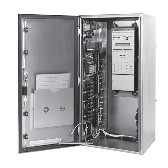
9/1/09 To determine the Micro-AT firmware version, press the ”EXAMINE” menu key followed by the “Next Item” key. The version of the Micro-AT firmware will be dis- played. For example, in the display below, the Micro-AT Firmware version is 2.1.2. - Page 4 Introduction Micro-AT Source-Transfer Control Communication User-furnished cable personal computer Figure 1. Communications card option for Micro-AT Source-Transfer Controls. S&C Instruction Sheet 515-506...
-
Page 5: Following Safety Instructions
(773) 338-1000; in Canada, call S&C Electric Canada Ltd. at (416) 249-9171. NOTICE Thoroughly and carefully read this instruction sheet before operating your Micro-AT Source- Transfer Control. Replacement If you need additional copies of this instruction sheet, contact your nearest S&C Sales Office, S&C Authorized Distributor, S&C Headquarters, or S&C Electric Canada Ltd. -
Page 6: Using The Communications Card
Step 3 Loosen the screw which retains the hinged lower panel of the Micro-AT control and swing open the lower panel. See Figure1 on page 4. (In pad-mounted gear which was originally fur nished with a Type AT-12 Source-Transfer Control, loosen the two screws which retain the door assembly of the Micro-AT control and swing open the door assembly.) - Page 7 The Matlink application will appear as shown below. Step 6 To establish the communication link between your com puter and the Micro-AT control: (a) Highlight and select Communications on the menu bar. A pop-up menu will appear listing communica tions options as shown below.
- Page 8 AT and Matlink communication settings should be set to 9600 bps. (c) Verify that the status window shows a changing clock display as shown below— indicating that communica tion with the Micro-AT control has been established. If a problem is encountered in establishing communi cation, an appropriate dialog box will be displayed explaining the problem.
-
Page 9: What Matlink Can Do
, and • The event log of the Micro-AT control. You’ll also be able to save to file the Micro-AT settings and the event log. You’ll have the capability of changing most settings of the Micro-AT control, either from your com- puter or from a file. -
Page 10: Viewing Micro-At Control Settings
Window on the menu bar, as shown below, and then highlight- ing and selecting the appropriate data window. If any of the field adjustable items need to be changed, refer to “Changing Micro-AT Control Settings” on page 13. - Page 11 , and Dwell Timer. (Preferred Source is also field adjustable but cannot be changed using Matlink. If necessary, Preferred Source can be changed at the Micro-AT control.) Bus Type, Voltage Sensing, Unbalance Install, Lockout Option, and Supervi- sory Control are all fac tory-set and are not field adjustable.
- Page 12 Using the Communications Card The actual left-source and right-source phase voltages, zero-sequence voltages, positive-sequence voltages, and negative-sequence voltages after normalizing are displayed. The field adjustable items in the Voltage data window which can be changed using Matlink include Loss of Source Level, Return of Source Level, Unbalance Level, and Overvoltage Level.
-
Page 13: Changing Micro-At Control Settings
The field adjustable items in the Time data window which can be changed using Matlink include Loss of Source Left, Loss of Source Right, Return of Source, Lockout Reset, Transition Dwell, Window Begin Time, Micro-AT Date, and Micro-AT Time. NOTICE A help screen is available for viewing settings. - Page 14 Using the Communications Card (b) Highlight and select Change. After a short delay, during which Matlink is retrieving data from the Micro-AT control, the Change Configuration data window will appear, similar to that shown below. The present settings and alterna- tive new settings of Con figuration items are listed.
- Page 15 Using the Communications Card (d) In this example, select Return “Auto.” The following screen will appear. (e) If an item listed in the Voltage, Current, or Time data window is to be changed, click on the More >> button. A new window will appear, similar to that shown below.
- Page 16 If the operating characteristics and operating parame ters are not to be saved to your computer as a config uration file, proceed to “Sending a Configuration File to the Micro-AT Control” on page 21. NOTICE A help screen is available for changing settings.
-
Page 17: Creating A Configuration File
Using the Communications Card Creating a Step 12 Configuration File To save to your computer the particular set of operating characteristics and operating parameters that you’ve checked and/or revised in Change Configuration, click on the Save to File button. The following screens will appear. Enter an appropriate name for the configuration file. - Page 18 Using the Communications Card You can also save to your computer a particular set of operating characteristics and operating parameters by highlighting and selecting File on the menu bar. A new pop-up menu will appear listing file options as shown below. S&C Instruction Sheet 515-506...
- Page 19 Using the Communications Card Highlight and select Save Config. The following screen will appear. Enter an appropriate name for the configuration file. In both instances, two files will be created, a binary (*.cfg) file and a text formatted (*.txt) file. A notification prompt will be displayed with the full file location infor mation.
-
Page 20: Downloading A Configuration File
Using the Communications Card Downloading a Step 13 Configuration File To download to your computer a particular configuration file that was created in Set- tings, click on the Load File button. The following screen will appear. Enter the name of the desired configuration file. NOTICE A help screen is available for configuration download. -
Page 21: Sending A Configuration File To Micro-At
Sending a Step 14 Configuraton File to To send to the Micro-AT control a configuration file that you’ve just created or a con- figuration file that you’ve just downloaded to your computer in Settings, click on the Micro-AT Send to AT button. After a short delay, during which Matlink is transmitting data to the Micro-AT control, the following screen will appear. -
Page 22: Viewing The "Not Ready" List
“Not Ready” List appear. In this particular case, the “ready” lamp is not lighted on the Micro-AT because the manual/automatic operation selector switch on the Micro-AT control is in “MANUAL”, the Right Operator is not in the Open position, the Left Operator is not in the Closed position, and the Low Tank Pressure alarm is active. -
Page 23: Troubleshooting Data-Line Circuit Problems
Problems Matlink. To view digital inputs to the Micro-AT control, click on the Inputs button bar. The following screen will appear. The true/false operating responses of the snap-action limit switches (and key interlocks, if applicable) at the inputs of the control are shown. -
Page 24: Uploading The Micro-At Control Event Log
Event Log stored in memory at any given time, in an event log. To upload the event log of the Micro-AT control to your computer, click on the Event Log button bar. The follow ing screen will appear. Click on the Load button. A dialog box will appear as shown below. - Page 25 Using the Communications Card Following the completion of the download of the Event Log, the Configuration Event Log will download during which a dialog box will appear as shown below: Note that the event log overview lists, for each event, the following: •...
- Page 26 Using the Communications Card Note that the event log detail lists, for a particular event, the following: • The event number; • The date/time of the event; • The event ID number; • The left-source phase and unbalance voltages during the event; •...
-
Page 27: Creating An Events File
Using the Communications Card Creating an To save to your computer an event log that you’ve uploaded, highlight and select File on the menu bar. A pop-up menu will appear listing file options as shown below. Events File Highlight and select Save Events. The following screen will appear. S&C Instruction Sheet 515-506... - Page 28 Using the Communications Card Enter an appropriate name for the events file. Two files will be created, a text output (*.log) file, which can be viewed using an application such as Note pad or Word, and a comma delimited (*.csv) file, which can be viewed using Excel.
-
Page 29: Appendix
Appendix Setting a Default The steps which follow apply only in instances where a Micro-AT Source-Transfer Control is not connected to your personal computer. Configuration Step A Turn on the computer and run the OS. Double-click on the MATLINK icon. Or open the File Manager (Win 3.1) or Windows Explorer (Win 95+) and select MATLINK;... - Page 30 NOTICE Each default value you select must conform with the corresponding factory-set item in your Micro-AT con trol(s). When you subsequently download the configu ration file you’re creating to a particular Micro-AT control, Matlink will compare each default value to the corresponding factory-set item in the CONFIGURE menu of the control.
- Page 31 Appendix For example, if Bus Type is to changed from “Common” to “Vista Common,” high- light and select the appropriate drop-down setting box. A new window will appear listing the alternative settings, similar to that shown below. In this example, select Bus Type “Vista Common.” The following screen will appear. S&C Instruction Sheet 515-506...
- Page 32 After you’ve selected the default values of all “Not Changeable” items, click on the OK button. The Change Configuration data window will appear, similar to that shown below. Proceed to “Changing Micro-AT Control Settings,” Step 11(c) on page 14. S&C Instruction Sheet 515-506...
Need help?
Do you have a question about the Micro-AT and is the answer not in the manual?
Questions and answers