S&C MIcro-AT Installation, Programming, And Operation Manual
Source-transfer control in a weatherproof enclosure
Hide thumbs
Also See for MIcro-AT:
- Quick start manual (2 pages) ,
- Operation (32 pages) ,
- Quick start programming manual (12 pages)
Table of Contents
Advertisement
MIcro-AT
Source-Transfer Control
®
In a Weatherproof Enclosure
Installation, Field Programming, and Operation
Table of Contents
Section
Qualified Persons . . . . . . . . . . . . . . . . . . . . . . . . . . . 2
Read this Instruction Sheet . . . . . . . . . . . . . . . . . . . 2
Retain this Instruction Sheet . . . . . . . . . . . . . . . . . . 2
Proper Application . . . . . . . . . . . . . . . . . . . . . . . . . . 2
Warranty . . . . . . . . . . . . . . . . . . . . . . . . . . . . . . . . . . 2
Understanding Safety-Alert Messages . . . . . . . . . . . 3
Following Safety Instructions . . . . . . . . . . . . . . . . . . 3
Replacement Instructions and Labels . . . . . . . . . . . 3
. . . . . . . . . . . . . . . . . . . . . . . . . 4
General . . . . . . . . . . . . . . . . . . . . . . . . . . . . . . . . . . . 5
Voltage Sensing . . . . . . . . . . . . . . . . . . . . . . . . . . . . 9
Unbalance Detection . . . . . . . . . . . . . . . . . . . . . . . . 9
Overcurrent Lockout . . . . . . . . . . . . . . . . . . . . . . . . .10
Remote Indication . . . . . . . . . . . . . . . . . . . . . . . . . . .10
Test Panel . . . . . . . . . . . . . . . . . . . . . . . . . . . . . . . . .10
Supervisory Control . . . . . . . . . . . . . . . . . . . . . . . . .10
Communications Card . . . . . . . . . . . . . . . . . . . . . . .10
Wi-Fi Adapter Kit . . . . . . . . . . . . . . . . . . . . . . . . . . .10
Normal Condition . . . . . . . . . . . . . . . . . . . . . . . . . . .11
Transfer on Loss-of-Source Voltage . . . . . . . . . . . . .11
Transfer on Return-of-Source Voltage . . . . . . . . . . .11
Transfer on Unbalance Condition . . . . . . . . . . . . . . .12
Overcurrent Lockout Condition . . . . . . . . . . . . . . . . .12
. . . . . . . . . . . . . . . . . . . . . . . . . . . . . . . . 14
The Display . . . . . . . . . . . . . . . . . . . . . . . . . . . . . . . .16
Error Messages . . . . . . . . . . . . . . . . . . . . . . . . . . . .18
Non-Numeric Items . . . . . . . . . . . . . . . . . . . . . . . . .19
Ready-Only Items . . . . . . . . . . . . . . . . . . . . . . . . . .19
Note: Micro-AT control instruction sheets are posted as PDF files at sandc.com/en/support/product-literature/.
Matlink™ software (all revisions) and the Human Machine Interface (HMI) software application installer (for Wi-Fi
adapter users) are available for download at sandc.com/en/support/sc-customer-portal/. If assistance is needed,
contact customerportal@sandc.com, or call (888) 762-1100.
January 20, 2020
© S&C Electric Company 2012-2020, all rights reserved
Page
Section
Configure Menu . . . . . . . . . . . . . . . . . . . . . . . . . . . .21
Voltage Menu . . . . . . . . . . . . . . . . . . . . . . . . . . . . . 25
Current Menu . . . . . . . . . . . . . . . . . . . . . . . . . . . . . 26
Time Menu . . . . . . . . . . . . . . . . . . . . . . . . . . . . . . . 27
Test Menu . . . . . . . . . . . . . . . . . . . . . . . . . . . . . . . . 28
Loss-of-Source Testing . . . . . . . . . . . . . . . . . . . . . . 30
Overcurrent-Lockout Testing . . . . . . . . . . . . . . . . . .31
Before Walking Away . . . . . . . . . . . . . . . . . . . . . . . 32
Event Menu . . . . . . . . . . . . . . . . . . . . . . . . . . . . . . . 33
Examine Menu . . . . . . . . . . . . . . . . . . . . . . . . . . . . 34
Non-Field Adjustable Items in the
Configure Menu . . . . . . . . . . . . . . . . . . . . . . . . . 38
Non-Field Adjustable Items in the
Voltage Menu . . . . . . . . . . . . . . . . . . . . . . . . . . 38
Event Identification Code Numbers in the
Event Menu . . . . . . . . . . . . . . . . . . . . . . . . . . . . 39
Discrete Inputs in the Examine Menu . . . . . . . . . . .41
Discrete Outputs in the Examine Menu . . . . . . . . . .41
Spare Circuit Cards . . . . . . . . . . . . . . . . . . . . . . . . 42
Spare Front Panel Assemblies . . . . . . . . . . . . . . . . 42
Static-Dissipative Work Surface . . . . . . . . . . . . . . 42
. . . . . . . . . . . . . . . . . . . . . . . . . . . . . . 35
. . . . . . . . . . . . . . . . . . . . . . . . . . . . . 36
Instruction Sheet 515-600
Page
. . . . . . . . . 20
Advertisement
Table of Contents

Related Manuals for S&C MIcro-AT


Summary of Contents for S&C MIcro-AT
-
Page 1: Table Of Contents
Ready-Only Items . . . . . . . . . . . . . . . . . . . . . . . . . .19 Note: Micro-AT control instruction sheets are posted as PDF files at sandc.com/en/support/product-literature/. -
Page 2: Introduction
Precautions on pages 3 through 4 . The latest version of this publication is available online in PDF format at sandc.com/en/support/product-literature/ . Retain this This instruction sheet is a permanent part of your Micro-AT Source-Transfer Control. Designate a location where you can easily retrieve and refer to this publication. Instruction Sheet... -
Page 3: Safety Information
Safety Information Understanding Several types of safety-alert messages may appear throughout this instruction sheet and on labels and tags attached to your Micro-AT Source-Transfer Control. Familiarize Safety-Alert yourself with these types of messages and the importance of these various signal words:... -
Page 4: Safety Precautions
Safety Precautions DANGER The Micro-AT Source-Transfer Control operates equipment at high voltage. Failure to observe the precautions below will result in serious personal injury or death. Some of these precautions may differ from your company’s operating procedures and rules . Where a discrepancy exists, follow your company’s operating procedures and rules . -
Page 5: Overview
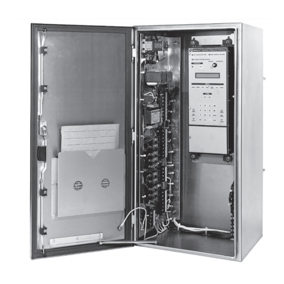
Instruction Sheet 515-530. For instructions on the use of the optional test panel feature for the Micro-AT control (catalog number suffix “-Y5”), refer to S&C Instruction Sheet 515-505. For instructions on the use of the optional communications card feature (catalog number suffix “-Y8”),... - Page 6 Overview The Micro-AT Source-Transfer Control in a weather proof enclosure includes the following standard features, illustrated in Figure 2 on page 7: • A MANUAL/AUTOMATIC operation selector switch • A two-line × 24-character backlit liquid-crystal display • An automatic-transfer READY indicating lamp, SOURCE-VOLTAGE indicating lamps, and an overcurrent LOCKOUT indi cating lamp with a reset key •...
- Page 7 Overview Control-voltage-seeking relay MANUAL/AUTOMATIC operation selector switch Input isolation transformers Two-line × 24-character backlit liquid-crystal display Signal-voltage input isolation assembly Test keys Keypad Instruction manual Stainless steel enclosure Voltage-transformer secondary fuses and grounding circuit slugs Terminal strips for external connections Figure 2.
- Page 8 (or reduced below a predetermined level) for a period of time sufficient to confirm that the loss is not transient, the Micro-AT control will initiate a loss-of-source transfer. The alternate-source interrupter switch is automatically opened and the preferred-source interrupter switch is then automati- cally closed, restoring service to the load.
-
Page 9: Voltage Sensing
If the voltage unbalance exceeds a preset reference level for a period of time sufficient to confirm that the loss is not transient, the Micro-AT control will initiate an automatic loss-of-source transfer to the other source. By monitor ing negative-sequence... -
Page 10: Overcurrent Lockout
Remote Indication A Remote Indication feature may also be optionally fur nished in the Micro-AT Source- Transfer Control In Weath erproof Enclosure. This feature permits remote monitoring of presence or absence of source voltages, manual or automatic operating mode, status of the READY indicator, EVENT indicator, and (if furnished) overcurrent lockout. -
Page 11: Operating Description
(See the “Overcurrent Lockout Condition” section on page 12.) At installations using three-phase source voltage sens ing, the Micro-AT control con- tinuously monitors the signal-input voltage level on each phase of the two sources and compares these inputs to the predetermined reference level to determine the status of each source. -
Page 12: Transfer On Unbalance Condition
Operating Description If the control has been programmed for “window return,” automatic return-of-source transfer to the normal condition will be performed in the same manner as for an “auto- matic return.” But return-of-source transfer is permitted to occur only if the time of day is within the specified time “window.”... - Page 13 Operating Description If the overcurrent is due to a fault that is cleared by a source-side protective device, the prolonged loss of source voltage will cause the associated source inter rupter switch to open, and the Overcurrent Lockout feature will pre vent the other source interrupter switch from closing into the fault.
-
Page 14: Installation
Installation Complete the following steps to install the Alduti-Rupter Switches, switch operators, and Micro-AT Source Transfer Control: STEP 1. Install the S&C Alduti-Rupter Switches and Type AS-1A or Type AS-10 Switch Operators in accordance with the S&C instruction sheets and erection drawings furnished with those devices. - Page 15 Installation STEP 4. Remove the voltage-transformer secondary fuses and grounding circuit slugs from the source-transfer control enclosure. See Figure 2 on page 7 for location of these components. STEP 5. Prepare a weather-tight entrance in the bottom of the enclosure in accordance with user’s practice.
-
Page 16: Features
The Micro-AT control features powerful built-in diag nostic tools. The control auto- matically records system status and the status of the device’s controller circuits every time a control operation occurs. - Page 17 Features RIGHT SOURCE VOLTAGE LEFT SOURCE indicating lamp VOLTAGE indicating lamp AUTOMATIC-TRANSFER MANUAL/AUTOMATIC READY indicating lamp operation selector switch Overcurrent LOCKOUT Two-line × 24-character backlit indicating lamp and RESET liquid-crystal display (LCD) Menu keys LAST and NEXT item keys TEST keys for simulating TEST keys for simulating overcurrent and loss of overcurrent and loss of...
-
Page 18: Error Messages
Features The display is indicating the access code must be entered before the value of loss- of-source voltage can be changed. As each digit of the access-code number is pressed, the display indicates that digit. When all the digits have been pressed—followed by the ENTER key—the display changes to: VOLTS: LOSS OF SOURCE 8 5 .0 VOLTS... -
Page 19: Non-Numeric Items
Features Non-Numeric A few field changeable items in the Conf igure menu require a non-numeric response. In such instances, the display will be similar to this: Items CONFIG: SELECT TRANSITION OPE N CHANGE Here the display is indicating the Open option has been selected as the type of transi- tion by which an automatic return-of-source transfer will be effected. -
Page 20: Field Adjustment And Programming
CONFIG: RESTORE VALUES. • When changing Select Bus Type setting or the Select Preferred setting in the Con- figure menu, the Micro-AT control will power down and reboot. A “System Startup” will be recorded in the event log. -
Page 21: Configure Menu
Place the manual/automatic operation selector switch in Manual mode to prevent automatic operation during adjust ment and programming. STEP 2. Set the operating characteristics of the Micro-AT control using the following procedure: (a) Press the CONFIGURE menu key. The following display will appear:... - Page 22 Field Adjustment and Programming Is the factory setting for each item (shown in the last column of the table, in boldface type) appropriate for this installation? If not, change it. For example, here is the display for CONFIG: SELECT PREFERRED with its factory setting, LEFT: CONFIG: SELECT PREFERRED LEFT...
- Page 23 Field Adjustment and Programming Press the CHANGE key. If the display prompts you to reenter the access- code number, do so. The fol lowing display will appear: CONFIG: NORMALIZE LEFT ENTER TO: NORMALIZE Press the ENTER key . The display will now look like this: CONFIG: NORMALIZE LEFT NORMAL IZE CHANGE...
- Page 24 Field Adjustment and Programming (f) The Micro-AT control can be programmed to accept a custom access-code number of your choosing, using the following procedure. If you don’t wish to enter a custom access-code number, proceed to Step 2(g). Here’s the...
-
Page 25: Voltage Menu
Field Adjustment and Programming If a different data-transfer bit rate is needed to estab lish communications between the Micro-AT control and the personal computer, press the CHANGE key. The following display will appear: CONFIG: COM 0 BIT RATE ENTER ACCESS CODE Press each digit of the access-code number, and then press the ENTER key. -
Page 26: Current Menu
Current Menu If CONFIG: LOCKOUT OPTION setting has been factory-set for Internal STEP 4. mode, set the lockout level of the Micro-AT con trol using the following procedure: (a) Press the CURRENT menu key. The following dis play will appear: Table 2. -
Page 27: Time Menu
Field Adjustment and Programming Time Menu STEP 5. Set the time-related operating parameters of the Micro-AT control using the following procedure. (a) Press the TIME menu key. The following display will appear: VOLTAGE: PRESS LAST/NEX T ITEM (b) Press the NEXT item key. The first item of the Time menu will appear on the... -
Page 28: Test Menu
Field Adjustment and Programming If the loss-of-left source time is to be set to some other value, press the CHANGE key. If the display prompts you to reenter the access-code number, do so. The display will now look like this: TIME: LOSS OF LEFT SOURCE 2 . - Page 29 Field Adjustment and Programming STEP 7. To check the functioning of the source-transfer control, perform the following: (a) Press the TEST menu key. (b) Press the NEXT item key (or LAST item key) repeatedly to scroll through the items, until the desired one is displayed. (c) When the “Test Lamps”...
-
Page 30: Operational Testing
Operational Testing The testing procedures described in this document should be per formed during initial startup and thereafter about once per year to verify the source-transfer control and its associated switch operators are fully functional. Because Type AS-1A and Type AS-10 Switch Operators may be readily decoupled from their associated Alduti-Rupter Switches, checkout of functional performance (e.g., oper ating sequence and timing) of the source-transfer con trol—and the switch operators—may be accomplished at any convenient time, without requiring an... -
Page 31: Overcurrent-Lockout Testing
Operational Testing MANUAL/AUTOMATIC operation selector switch in Manual mode and recouple each switch operator to its interrupter switch. Then, place the MANUAL/AUTOMATIC operation selector switch in Automatic mode. To ensure the source-transfer control is ready for automatic operation, perform the final checks outlined under the “Before Walking Away” section on page 32. -
Page 32: Before Walking Away
Operational Testing Before Walking Away So the source-transfer control is ready for auto matic operation, verify the following: • The manual/automatic operation selector switch is in Automatic mode. • If the Supervisory Control option is enabled, the Supervisory manual/automatic dry contact is closed. •... -
Page 33: Diagnostic Tools
Diagnostic Tools Event Menu The Micro-AT control automatically records system status and the status of the device’s controller circuits each time a control operation occurs. Each such operation, referred to as an “event,” is indicated by the illumination of a lamp on the EVENT menu key and is available for display under this menu. -
Page 34: Examine Menu
Diagnostic Tools To read an item listed under the Event menu, per form the following: (a) Press the EVENT menu key. (b) Press the NEXT item key (or LAST item key) repeatedly to scroll through the items associated with the latest event, until the desired one is dis played. (The number in the upper right-hand corner of the display indicates the event identification code number—from 0 to 523.) (c) If the same item associated with an earlier event is desired, use the “... -
Page 35: Maintenance
An odd-looking clock display is an indication that the clock battery requires replace- ment. Refer to the clock battery specifications on page 37. Note: The Micro-AT CPU Card battery should be replaced every 10 years. Catalog num- ber TA-2299 is available from S&C. -
Page 36: Specifications
Supervisory control . Includes facilities for switch operation from a remote location Communications card . Permits local uploading of “events” and settings from the Micro-AT control to a user-furnished personal computer, as well as downloading of the user’s standard operating parameters ②③... - Page 37 ● Used in tandem with the HMI application software . To obtain the additional items are required to make the Micro-AT control components HMI software application, download the installer from the S&C customer and firmware compatible with the Wi-Fi adapter kit .
-
Page 38: Appendix
Appendix Table 9. Non-Field Adjustable Items in the Configure Menu Non-Field-Adjustable Item Description CONFIG: Setting of the control to accommodate Common bus or Split bus (in switchgear applications), “PAD MNT” bus (in pad-mounted gear applications) . A fourth setting, “SPLTCOM,” applies to split-bus switchgear in which the bus- SELECT BUS TYPE tie interrupter switch does not function automatically;... -
Page 39: Event Menu
Appendix Table 11. Event Identification Code Numbers In The Event Menu Code Code Description Description Number Number General Events Overcurrent Latch Events Latch OC Left Start LR Timer Left Cancel LR Timer Left Reset OC Latch Left Enter Normal Left Enter Restraint Left Enter Reset Restraint Left System Startup... - Page 40 Appendix Table 11. Event Identification Code Numbers In The Event Menu—Continued Code Code Description Description Number Number General Events Overcurrent Latch Events Bus Type changed to COMMON Bus Type changed to SPLIT Bus Type changed to SPLIT-COM Bus Type changed to PAD MNT UPS Application set to UPS ON RIGHT Bus Type changed to VISTA COM Transition set to OPEN...
-
Page 41: Discrete Inputs In The Examine Menu
Appendix Table 12. Discrete Inputs In The Examine Menu Non-Field-Adjustable Item Description EXAMINE: L SW OPEN Left Switch Open L SW CLOSED Left Switch Closed L SW COUPLED Left Switch Coupled L SW TR OPEN Left Switch Trip to Open (Manual Open Push button) L SW TR CLOSED Left Switch Trip to Close (Manual Close Push button) R SW OPEN... -
Page 42: Spare Circuit Cards
Appendix Table 14. Spare Circuit Cards For Source-Transfer Control Item Catalog Number Catalog Number Suffix Power supply card 39060 TA-2257 CPU card 39060 TA-2283R1 Digital input card 39060 TA-2285 Analog input card 39060 TA-2284-3 All (except -Y5) TA-2286-3 Burden card 39060 TA-2280-3 Relay output card...
Need help?
Do you have a question about the MIcro-AT and is the answer not in the manual?
Questions and answers