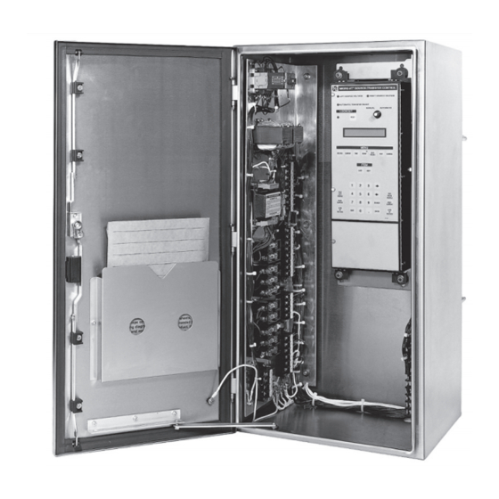
S&C Micro-AT Quick Start Programming Manual
Source-transfer control
Hide thumbs
Also See for Micro-AT:
- Quick start manual (2 pages) ,
- Installation, programming, and operation manual (42 pages) ,
- Operation (32 pages)
Table of Contents
Advertisement
Quick Links
Micro-AT
Source-Transfer Control
®
Table of Contents
Section
Qualified Persons . . . . . . . . . . . . . . . . . . . . . . . . . . . 2
Read this Instruction Sheet . . . . . . . . . . . . . . . . . . . 2
Retain this Instruction Sheet . . . . . . . . . . . . . . . . . . . 2
Proper Application . . . . . . . . . . . . . . . . . . . . . . . . . . 2
Warranty . . . . . . . . . . . . . . . . . . . . . . . . . . . . . . . . . . 2
September 30, 2019
© S&C Electric Company 1993-2019, all rights reserved
Quick-Start Programming
Page
Section
Understanding Safety-Alert Messages . . . . . . . . . . . 3
Following Safety Instructions . . . . . . . . . . . . . . . . . . 3
Replacement Instructions and Labels . . . . . . . . . . . 3
. . . . . . . . . . . . . . . . . . . . . . . . . 4
Instruction Sheet 515-530
Page
. . . . . . . . . . . . . . . . . . . 5
Advertisement
Table of Contents

Summary of Contents for S&C Micro-AT
-
Page 1: Table Of Contents
Micro-AT Source-Transfer Control ® Quick-Start Programming Table of Contents Section Page Section Page Introduction Safety Information Qualified Persons . . . . . . . . . . . . . . . . . . . . . . . . . . . 2 Understanding Safety-Alert Messages . -
Page 2: Introduction
Precautions on pages 3 and 4 . The latest version of this publication is available online in PDF format at sandc.com/en/support/product-literature/ . Retain this This instruction sheet is a permanent part of the S&C Micro-AT Source-Transfer Control. Designate a location where it can be easily retrieved and refer to. Instruction Sheet... -
Page 3: Safety Information
Safety Information Understanding Several types of safety-alert messages may appear throughout this instruction sheet and on labels and tags attached to the Micro-AT Source-Transfer Control. Familiarize Safety-Alert yourself with these types of messages and the importance of these various signal words:... -
Page 4: Safety Precautions
Safety Precautions DANGER The equipment controlled by the Micro-AT Source-Transfer Control operates at high voltage. Failure to observe the precautions below will result in serious personal injury or death. Some of these precautions may differ from your company’s operating procedures and rules . -
Page 5: Quick-Start Programming
NOTICE When changing the Select Bus Type or Select Preferred settings in the Configure menu, the Micro-AT control will power down and reboot . A System Startup event will be recorded in the event log . Place the MANUAL/AUTOMATIC operation selector switch in Manual mode STEP 1. - Page 6 Quick-Start Programming Table 1. Field adjustable items in the Configure menu. Field Adjustable Item Operating State Description Displayed If CONFIG: or Range ① CONFIG: SELECT BUS TYPE has been SELECT PREFERRED Assignment of “Left” Or “Right” as preferred source factory set for “COMMON,” “PAD MNT,” LEFT, RIGHT “VISTA COM,”...
- Page 7 Quick-Start Programming Is the factory-setting for each item (shown in the last column of the table, in boldface type) appropri ate for this installation? If not, change it. For example, here is the display for CONFIG: SELECT PREFERRED with its factory setting, LEFT: ECONFIG: ESELECTEPREFERRED ELEFTEEEEEEEEEEEEEECHANGE If the right source is the preferred source at this installation, press the...
- Page 8 VOLTSEEEEEEEEECHANGE Set the right-source base voltage the same way. (f) The Micro-AT control can be programmed to accept a custom access code number of your choosing, using the following procedure. Note: If you don’t wish to enter a custom access-code number, proceed to Step 2(g).
- Page 9 Refer to Instruc tion Sheet 515-606. Note: If the Micro-AT control has not been furnished with the communi- cations card, proceed to Step 3. Here’s the display for CONFIG: COM Ø BIT RATE with its factory...
- Page 10 Quick-Start Programming (c) Press the <Next> item key repeatedly to scroll to each field-adjustable item of the Volts menu, as listed in Table 2. Is the factory setting for each item (shown in the last column of the table, in boldface type) appropriate for this installation? If not, change it. For example, here is the display for VOLTS: LOSS OF SOURCE with its factory setting, 85 Volts: VOLTS:...
- Page 11 <6>, <0>, and <0> keys would be pressed followed by the <Enter> key. CURRENT: LOCKOUT LEVEL 600 AMPS CHANGE STEP 5. Set the time-related operating parameters of the Micro-AT control using the following procedure: (a) Press the <Time> menu key. The following display will appear: TIME: PRESS LAST/NEXT ITEM (b) Press the <Next>...
- Page 12 Quick-Start Programming (c) Press the <Next> item key repeatedly to scroll to each item of the Time menu, as listed in Table 3. Each item of the Time menu is field-adjustable. Is the factory setting for each item (shown in the last column of the table, in boldface type) appropriate for this installation? If not, change it.


Need help?
Do you have a question about the Micro-AT and is the answer not in the manual?
Questions and answers