Table of Contents
Troubleshooting

Related Manuals for MKS 250E


Summary of Contents for MKS 250E
- Page 1 120552-P1 Rev A, 2/97 Instruction Manual MKS Type 250E Pressure/Flow Controller Six Shattuck Road Fax: (978) 975-0093 Andover, MA 01810-2449 E-mail: mks@mksinst.com (800) 227-8766 or (978) 975-2350 Web site: http://www.mksinst.com...
- Page 2 MKS sales representative or distributor from which the equipment was purchased or, in the case of a direct purchase from MKS, with the MKS home office in Andover, Massachusetts, USA.
- Page 3 120552-P1 Rev A, 2/97 MKS Type 250E Pressure/Flow Controller...
- Page 4 All rights reserved. No part of this work may be reproduced or transmitted in any form or by any means, electronic or mechanical, including photocopying and recording, or by any information storage or retrieval system, except as may be expressly permitted in writing by MKS Instruments, Inc.
-
Page 5: Table Of Contents
Table of Contents Table of Contents Safety Information........................1 Symbols Used in This Instruction Manual..............1 Symbols Found on the Unit ..................2 Safety Procedures and Precautions ................3 Chapter One: General Information..................5 Introduction ....................... 5 How This Manual is Organized.................. 7 Customer Support ...................... - Page 6 Table of Contents General Information ....................23 Multi-Gas Ratio Control.....................23 Front Panel Controls ....................24 Rear Panel Controls....................26 Labels ........................27 Serial Number Label ..................27 Chapter Four: Operation ......................29 How To Setup the Controller..................29 How To Use Manual Control..................30 How To Tune-Up the Controller.................30 How To Use the Bias Control..................31 How To Use the Normal/Reverse Switch..............32 How To Use External Control ..................32...
- Page 7 Table of Contents Index............................49...
- Page 8 Table of Contents...
- Page 9 List of Figures and Tables List of Figures and Tables Figures Figure 1: Preferred Method To Connect a Shielded Cable............12 Figure 2: Alternate Method To Connect a Shielded Cable ............. 12 Figure 3: Standard Pressure Control Setup................18 Figure 4: Multi-Gas Ratio Control..................18 Figure 5: Front Panel Controls ....................
- Page 10 List of Figures and Tables viii...
-
Page 11: Safety Information
Safety Information Safety Information Symbols Used in This Instruction Manual Definitions of WARNING, CAUTION, and NOTE messages used throughout the manual. Warning The WARNING sign denotes a hazard. It calls attention to a procedure, practice, condition, or the like, which, if not correctly performed or adhered to, could result in injury to personnel. -
Page 12: Symbols Found On The Unit
Safety Information Symbols Found on the Unit The following table describes symbols that may be found on the unit. Definition of Symbols Found on the Unit Protective earth (ground) Off (Supply) Earth (ground) On (Supply) IEC 417, No.5019 IEC 417, No.5008 IEC 417, No.5017 IEC 417, No.5007 Frame or chassis... -
Page 13: Safety Procedures And Precautions
DO NOT SUBSTITUTE PARTS OR MODIFY INSTRUMENT Do not install substitute parts or perform any unauthorized modification to the instrument. Return the instrument to an MKS Calibration and Service Center for service and repair to ensure that all safety features are maintained. - Page 14 Safety Information USE THE PROPER POWER SOURCE This product is intended to operate from a power source that does not apply more voltage between the supply conductors, or between either of the supply conductors and ground, than that specified in the manual. USE THE PROPER FUSE Use only a fuse of the correct type, voltage rating, and current rating, as specified for your product.
-
Page 15: Chapter One: General Information
Chapter One: General Information Introduction The MKS Type 250E Pressure/Flow Controller will control any one of a variety of flow valves to accurately maintain a set pressure or flow. The 250 controller can provide a ±15 VDC output and accepts inputs from a variety of pressure transducers and mass flow meters. Two controllers can be combined to provide two gas ratio control. - Page 16 Introduction Chapter One: General Information In more elaborate systems, the chamber pressure may be controlled with one controller while a known mass flow is admitted with the aid of a laminar flow element and its separate controller. The 250 controller takes the DC pressure signal, compares it to the set point, and positions the valve so that it drives the actual pressure to the set pressure.
-
Page 17: How This Manual Is Organized
Calibration and Service Center before shipping. The ERA Number expedites handling and ensures proper servicing of your instrument. Please refer to the inside of the back cover of this manual for a list of MKS Calibration and Service Centers. Warning All returns to MKS Instruments must be free of harmful, corrosive, radioactive, or toxic materials. - Page 18 Customer Support Chapter One: General Information This page intentionally left blank.
-
Page 19: Chapter Two: Installation
Chapter Two: Installation How To Unpack the Type 250 Unit MKS has carefully packed the Type 250 unit so that it will reach you in perfect operating order. Upon receiving the unit, however, you should check for defects, cracks, broken connectors, etc., to be certain that damage has not occurred during shipment. -
Page 20: Interface Cables
System Interface Cables The system interface cables include cables to connect the 250 controller to a transducer or to a valve, as well as the adapter cable necessary to replace a 250A-C unit with a 250E unit. System Interface Cables To Connect the 250 Unit To... -
Page 21: Generic Shielded Cable Description
Table 2: System Interface Cables Generic Shielded Cable Description MKS offers a full line of cables for all MKS equipment. Should you choose to manufacture your own cables, follow the guidelines listed below: 1. The cable must have an overall metal braided shield, covering all wires. Neither aluminum foil nor spiral shielding will be as effective;... -
Page 22: Figure 1: Preferred Method To Connect A Shielded Cable
Interface Cables Chapter Two: Installation Example 1: Preferred Method To Connect Cable (shown on a transducer) Metal Cable Clamp Screw Transducer Split Lock Washer Overall Insulation External Tooth Lock Washer (if present) Bare Metal Cable Clamp Transducer Housing Making Firm Contact To Braid Braid Here Is Desirable Optional Plastic or Metal Cable (but not usually necessary) -
Page 23: Product Location And Requirements
Chapter Two: Installation Product Location and Requirements Product Location and Requirements The Type 250 unit meets the following criteria: • POLLUTION DEGREE 2 in accordance with IEC 664 • Transient overvoltages according to INSTALLATION CATEGORY II Operating Environmental Requirements • Ambient Operating Temperature: 0°... -
Page 24: Setup
Setup Chapter Two: Installation Setup System Design There are several considerations that must be dealt with before start-up: Valve Selection The correct valve must be selected to allow a reasonable fast time response. For example: Assume a system whose pumping speed is 150 liters/sec. and whose volume is 100 liters. This means that the pump down time constant (T.C.) will be 0.7 seconds. - Page 25 Chapter Two: Installation Setup Lags Lags must be removed. If lags (delays) are built into a system, stabilization will be difficult or impossible. Lag may be introduced pneumatically in two areas: the tubing to the sensor and the tubing to the valve. Both tubing runs must be less than 6 inches long and no less than ¼...
-
Page 26: Mounting Instructions
No special precautions are needed to protect the unit from ordinary mechanical shock and vibration. A rack mounting kit (RM-6) is available from MKS for single or dual unit rack mounting. -
Page 27: Interconnections
Chapter Two: Installation Setup Transducer Any pressure transducer which delivers at least 0.1 Volt full scale, can be used as the feedback element for total pressure control (refer to Optional Equipment, page 9). The pressure transducer should be mounted so that it is firmly supported, while at the same time, isolated from any vibration. -
Page 28: Figure 3: Standard Pressure Control Setup
Setup Chapter Two: Installation Figure 3: Standard Pressure Control Setup Figure 4: Multi-Gas Ratio Control... -
Page 29: Electrical Information
Chapter Two: Installation Electrical Information Electrical Information Fuses The line fuses protect the internal circuitry; both sides of the line are fused. The fuse values are listed in Table 4. Fuse Information Voltage Fuse Type 115 VAC 0.50 A (T) / 250 V / 5 x 20 mm 230 VAC 0.25 A (T) / 250 V / 5 x 20 mm Table 4: Fuse Information... -
Page 30: Valve Connector
CB251-2-10. If you are installing the 250 controller into an existing system that uses the old (hex) connector cables, an adapter cable is required. Use cable CB250-12-10 or CB250S-12-10 to replace a Type 250A-C controller with the Type 250E controller. Note Overall metal braided shielded cables, properly grounded at both ends, are required during use to meet CE Mark specifications. -
Page 31: Input Connector
Chapter Two: Installation Electrical Information Input Connector This 14-pin Amphenol connector allows you to connect the 250 controller to a transducer. It provides ±15V power and accepts the input pressure signal from the transducer. Input Connector Pinout Assignment (+) Pressure Input Reserved D.C. -
Page 32: Interface Connector
Electrical Information Chapter Two: Installation Interface Connector This 14-pin Amphenol connector provides access to the miscellaneous outputs, ±15V power, and external inputs to the 250 controller. Since there are a limited number of spare pins on the Interface connector, the exact pinout depends on which options are installed. •... -
Page 33: Chapter Three: Overview
Chapter Three: Overview General Information Chapter Three: Overview General Information The Type 250 controller is a versatile controller capable of pressure, flow, or flow ratio control. It is used for pressure control when a pressure transducer provides the feedback signal, and flow control when a mass flow meter provides the feedback. -
Page 34: Front Panel Controls
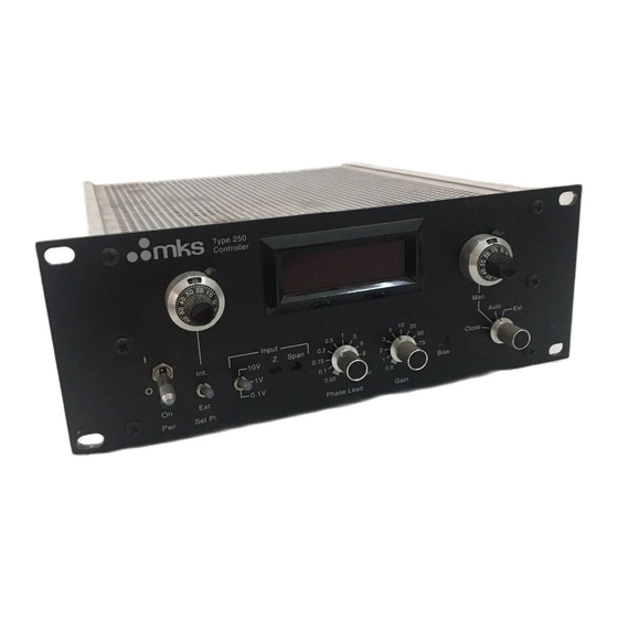
Front Panel Controls Chapter Three: Overview Front Panel Controls Set Point Control Error Meter Manual Control On/Power Bias Valve Mode Switch Int/Ext Span Z (Zero) Gain 10V/1V/0.1V Bias Phase Lead Figure 5: Front Panel Controls ON/POWER - Controls the AC power to the 250 controller. The LED indicator below it indicates when the power is on, that is, the plug is in and the fuse is alive. - Page 35 Chapter Three: Overview Front Panel Controls GAIN - The GAIN setting determines the overall gain of the controller and should be as high as possible without making the system unstable. The higher the gain, the smaller the dead band. If some overshoot is tolerable, better control (less dead band) can be achieved.
-
Page 36: Rear Panel Controls
(hex) connector cables, an adapter cable is required. Use adapter cable CB250-12-1 or CB250S-12-1 to replace a Type 250A-C controller with the Type 250E controller. Refer to Table 5, page 20, for the Valve connector pinout. INTERFACE - This 14-pin Amphenol connector provides access to the miscellaneous outputs, ±15V power, and external inputs to the controller. -
Page 37: Labels
250E-1-A-PLO MKS In stru ment s, Inc. Made in t he USA Figure 7: Serial Number Label The instrument is identified as “250E - X - Y - Z”, where: 250E Type number Number of set point controls Display Option Option Refer to Appendix B: Model Code Explanation, page 47, for more information. - Page 38 Labels Chapter Three: Overview This page intentionally left blank.
-
Page 39: Chapter Four: Operation
Chapter Four: Operation How To Setup the Controller Chapter Four: Operation How To Setup the Controller Before plugging in the AC line cord, turn the power switch OFF and perform the following steps: 1. Ensure that the voltage selector on the rear panel is in the proper position and that the fuse has the proper rating. -
Page 40: How To Use Manual Control
How To Use Manual Control Chapter Four: Operation How To Use Manual Control The 250 controller has a MANUAL control which, when properly adjusted, should make the initial valve turn-on quick and easy. Place the valve selector in MANUAL and increase the MANUAL control setting. During the first few turns nothing will happen to the flow (or pressure in the system). -
Page 41: How To Use The Bias Control
Chapter Four: Operation How To Use the Bias Control How To Use the Bias Control The BIAS control establishes a floor, or minimum, signal level to the valve which prevents the integrator from “winding up” or going too far into saturation. The signal to the valve consists of the bias level plus the controller signal. -
Page 42: How To Use The Normal/Reverse Switch
How To Use the Normal/Reverse Switch Chapter Four: Operation How To Use the Normal/Reverse Switch Most applications will require that when the pressure (or flow) is greater than the set point, the valve should have less drive to return the process to the proper value. This is “normal” operation and assumes that the output of the pressure (or flow) transducer increases positively for increasing pressure (or flow). -
Page 43: How To Use The Dvm Option
Chapter Four: Operation How To Use the DVM Option How To Use the DVM Option The 250 controller can optionally be supplied with a 4½ place DVM to display the controlled parameter (pressure or flow). The display is from 0000 to 10000 and the decimal point can be positioned at any convenient location with switches inside the controller. -
Page 44: How To Use The Multiple Set Point Option
How To Use the Multiple Set Point Option Chapter Four: Operation How To Use the Multiple Set Point Option The Multiple Set Point Option (MSO) provides up to four front panel set point pots which can be selected either from the front panel, or remotely. When selected, each set point pot provides a precision reference for the controller, which will maintain the control pressure (or flow) at the preset level. -
Page 45: Interconnections
Chapter Four: Operation How To Use the Multiple Set Point Option Interconnections The remote set point select lines are brought out on the Interface connector, and are listed in Table 8. The digital ground should be connected to the circuit ground of the digital instrument that is selecting set points. -
Page 46: How To Use The Process Limit Option
How To Use the Process Limit Option Chapter Four: Operation How To Use the Process Limit Option The Process Limit Option (PLO) provides a logic signal (+5V) and relay closure when the controller error deviates from zero by more than the process limit. The process limit can be set by an internal control to any range from ±0.5 to ±100%. -
Page 47: Interconnections
Chapter Four: Operation How To Use the Process Limit Option Interconnections Since there are a limited number of spare pins on the Interface connector, the exact pinout will depend on which options are installed. Some examples are listed in Table 9. Process Limit Option Pinout Interface Connector... - Page 48 How To Use the Process Limit Option Chapter Four: Operation This page intentionally left blank.
-
Page 49: Chapter Five: Maintenance And Troubleshooting
Instruments immediately. If it is necessary to return the unit to MKS, obtain an ERA number (Equipment Return Authorization Number) from a MKS Service Center before shipping. Please refer to the inside back cover of this manual for a list of MKS Calibration and Service Centers. Maintenance Periodically check for wear on the cables and inspect the enclosure for visible signs of damage. -
Page 50: How To Perform The Controller Alignment Procedure
Maintenance Chapter Five: Maintenance and Troubleshooting How To Perform the Controller Alignment Procedure The following alignment procedure should be followed to verify the zero and full scale alignment of the 250 controller. Allow the controller to warm up for at least 30 minutes. Note that the main P.C. -
Page 51: Table 10: Test Point Voltages
Chapter Five: Maintenance and Troubleshooting Maintenance Test Point Voltages Condition Test Point Voltage Control (+) 15 V + 15.00 ±.05 R118 Supply Jumper (-) 15 V Supply - 15.00 ±.05 R125 Jumper Input = 0.000V TP-6 0.000 Zero (R33) Input = 0.000V TP-1 0.000 Output Zero (R89) -
Page 52: Troubleshooting
Troubleshooting Chapter Five: Maintenance and Troubleshooting Troubleshooting To locate the cause of trouble, follow steps 1, 2, and 3 in sequence. 1. Check for obvious problems such as power off, open fuse, defective line cord, input power failure, or loose connections. 2. -
Page 53: Table 11: Troubleshooting Chart
Chapter Five: Maintenance and Troubleshooting Troubleshooting Troubleshooting Chart Symptom Checks and Probable Causes Error Meter shows oscillation or noise a. Check to see if input gas pressure is steady. (Optional DVM reading is noisy) b. Check that pressure transducer has a steady output (vibration isolation may be required). - Page 54 Troubleshooting Chapter Five: Maintenance and Troubleshooting This page intentionally left blank.
-
Page 55: Appendix A: Product Specifications
Appendix A: Product Specifications Appendix A: Product Specifications CE Mark Compliance EMC Directive 89/336/EEC Electromagnetic Compatibility Low-Voltage Directive 73/23/EEC Low-Voltage Requirements II, according to EN 61010-1 Installation Category 2, according to IEC 664 Pollution Degree Product Safety Directive 92/59/EEC Product Safety and Liability External Set Point 0 to 5 VDC analog (40K load impedence) Fuse Ratings... - Page 56 Appendix A: Product Specifications This page intentionally left blank.
-
Page 57: Appendix B: Model Code Explanation
Type Number (####) This designates the model number of the instrument. The controller is identified as the Type 250E. Number of Set Point Controls (X) Three types of set point control (multiple set point option) are available, designated by a single number code. - Page 58 Model Code Appendix B: Model Code Explanation Display Option (Y) Two types of displays are available, designated by a single letter code. Ordering Code Standard: Analog Error (Deviation) Meter Optional: 4½ Place Digital Display (of input signal) Option (Z) One functional option is available, designated by a three letter code. Ordering Code Process Limit Option...
- Page 59 Index Index Cables, 10 PCS, 23 Connectors Pollution Degree, 13 interface, 26 Pressure control signal, 23 Customer support, 7 Returning the product, 7, 9 Installation Category, 13 Serial number label, 27 Labels, 27 Setup controller, 16 interconnections, 17 Manual organization, 7 mass flow meter, 17 Messages, definitions of, 4 system design, 14...
Need help?
Do you have a question about the 250E and is the answer not in the manual?
Questions and answers