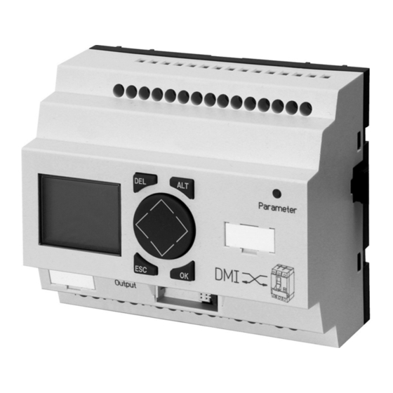
Eaton NZM2 Manual

Eaton NZM2 Manual

Circuit-breaker communication system
Hide thumbs Also See for NZM2:
Table of Contents

Advertisement

• FAST SHIPPING AND
DELIVERY
• TENS OF THOUSANDS OF
IN-STOCK ITEMS
• EQUIPMENT DEMOS
• HUNDREDS OF
MANUFACTURERS
SUPPORTED
• LEASING/MONTHLY
RENTALS
• ITAR CERTIFIED
SECURE ASSET SOLUTIONS
Artisan Technology Group
new and certified-used/pre-owned equipment
SERVICE CENTER REPAIRS
Experienced engineers and technicians on staff
at our full-service, in-house repair center
View
Instra
REMOTE INSPECTION
SM
Remotely inspect equipment before purchasing with
www.instraview.com
our interactive website at
Contact us:
(888) 88-SOURCE | sales@artisantg.com | www.artisantg.com
is your source for quality
WE BUY USED EQUIPMENT
Sell your excess, underutilized, and idle used equipment
We also offer credit for buy-backs and trade-ins
www.artisantg.com/WeBuyEquipment
LOOKING FOR MORE INFORMATION?
Visit us on the web at
information on price quotations, drivers, technical
specifications, manuals, and documentation
www.artisantg.com
for more

Advertisement

Table of Contents
loading

Summary of Contents for Eaton NZM2

  • Page 1 Artisan Technology Group is your source for quality new and certified-used/pre-owned equipment SERVICE CENTER REPAIRS WE BUY USED EQUIPMENT • FAST SHIPPING AND DELIVERY Experienced engineers and technicians on staff Sell your excess, underutilized, and idle used equipment at our full-service, in-house repair center We also offer credit for buy-backs and trade-ins •...
  • Page 2 11/04 AWB1230-1441GB Circuit-Breaker Communication System Eaton Corporation Eaton Adressen weltweit: Eaton ist ein führendes Energie- Management-Unternehmen. Weltweit www.moeller.net/address ist Eaton mit Produkten, Systemen und Dienstleistungen in den Bereichen Electrical, E-Mail: info-bonn@eaton.com Hydraulics, Aerospace, Truck und Automotive tätig. Internet: www.eaton.com/moellerproducts www.eaton.com...
  • Page 3 08/03 edition 08/04 edition 11/04 See revision protocol in the “About this manual“ chapter © 2002 by Eaton Industries GmbH, 53105 Bonn Production: Heidrun Riege Translation: David Long All rights reserved, including those of the translation. No part of this manual may be reproduced in any form (printed, photo-...
  • Page 4 Warning! Dangerous electrical voltage! Before commencing the installation • Disconnect the power supply of the device. • Suitable safety hardware and software measures should be implemented for the • Ensure that devices cannot be accidentally I/O interface so that a line or wire breakage restarted.
  • Page 5 • Measures should be taken to ensure the • Wherever faults in the automation system proper restart of programs interrupted may cause damage to persons or property, after a voltage dip or failure. This should external measures must be implemented to not cause dangerous operating states even ensure a safe operating state in the event for a short time.
  • Page 6 11/04 MN01219002Z-EN Contents User Notes Target group Proper use – Improper use Modification index Writing conventions Device designation System overview System concept Device overview DMI system – Keypad – Operating principle – Menu structure Engineering and installation – Mounting – Connecting fieldbus modules –...
  • Page 7 11/04 MN01219002Z-EN Contents Diagnostics – NZM status – DMI Status – Diagnostics Alarm messages Connection to bus systems What to do if ...? Technical data – General – Ambient conditions – Power supply – Digital inputs (24 V DC) – Digital outputs (relays) NZM-XDMI-DPV1 (PROFIBUS-DPV1 Interface for DMI) System overview...
  • Page 8 11/04 MN01219002Z-EN Contents What Happens If ...? Technical Data – General – Ambient temperatures – Ambient mechanical conditions – Electromagnetic compatibility (EMC) – Dielectric strength – Tools and cable cross-sections – Power supply – Status LEDs – PROFIBUS-DP Dimensions Index Artisan Technology Group - Quality Instrumentation ...
  • Page 9 11/04 MN01219002Z-EN Artisan Technology Group - Quality Instrumentation ... Guaranteed | (888) 88-SOURCE | www.artisantg.com...
  • Page 10 11/04 MN01219002Z-EN User Notes This manual describes the communication link between the NZM2, 3, and 4 circuit-breakers, • a local Data Management Interface (DMI) and • a fieldbus system. The communication system allows the user to interrogate diagnostics and operating data, log current values, implement the parameter assignment and control of the circuit-breakers locally or via a network.
  • Page 11 11/04 MN01219002Z-EN User Notes Improper use The DMI must not be used as a replacement for components from safety controls such as safety controls for furnaces, cranes, Emergency-Stop or two-hand controls. Modification index From the 11/04 edition the manual AWB1230-1441GB has been renamed to MN01219002Z-EN.
  • Page 12 11/04 MN01219002Z-EN Modification index Edition Page Subject Modi- Omitted date fied 08/03 „COM“ 60ff. „Trip“, „Alarm“ 62ff. „Diagnostics“ „Connection to bus systems“ PROFIBUS-DP 75ff. All of chapter 3„NZM-XDMI-DPV1 (PROFIBUS-DPV1 Interface for DMI)“ 04/03 25, 68 Connecting an auxiliary switch to the The circuit-breaker assumes the short- circuit and overload disconnection.
  • Page 13 11/04 MN01219002Z-EN User Notes Edition Page Subject Modi- Omitted date fied 11/02 10, 11 Main menu 24, 25 Display menu I/O status Motor starter 31ff. Input menu Reset 36, 37 Table 37ff. H select, Reset H-Sel Motor start. Startup behaviour Diagnostics menu Commands 64, 65...
  • Page 14 11/04 MN01219002Z-EN Writing conventions Abbreviations and symbols used in this manual have the following meanings: Data Management Interface Circuit-breaker in general Distribution circuit protection electronic (AE internal company abbreviation) Motor protection electronic Full protection electronic (VE internal company abbreviation) indicates actions to be taken. Indicates interesting tips and additional information Note Warns of a hazardous situation that could result in...
  • Page 15 System overview The following communication components are the accessories that are used for establishing communication with the NZM2, 3 and 4 circuit-breakers. • DMI for connecting the circuit-breaker; manages the NZM data and relays it to the fieldbus interface when necessary (a chapter 2 Page 11).
  • Page 16 11/04 MN01219002Z-EN System concept The DMI is the Data Management Interface for NZM circuit- breakers of frame sizes 2, 3 and 4. It supports user-friendly and local • Parameter setting, • Operation and • Monitoring of the circuit-breakers, as well as •...
  • Page 17 11/04 MN01219002Z-EN Device overview Figure 1: Setup of the DMI a Power supply b 6 digital inputs c Interface for the interface modules d Parameters LED e Keypad f Interface for connecting circuit-breaker or PC g 6 digital outputs h Display Artisan Technology Group - Quality Instrumentation ...
  • Page 18 11/04 MN01219002Z-EN DMI system DMI system Keypad DEL + ALT: Change from any menu to the Special menu DEL + ESC: Change from any submenu to the main menu Cursor buttons: Change menu item, change value ÍÚ change position ú í OK: Continue, confirm selection ESC: Move back, cancel Cursor display: The cursor flashes.
  • Page 19 11/04 MN01219002Z-EN Menu structure Main menu Timeout or three errors MAIN MENU Input Menu PW Entry Alt + DEL Display Menu 0000 Correct entry Display Diagnostics INPUT MENU NZM Status Parameters DMI Status Commands Special Menu Remote op. Q Assignment I Assignment Motor start.
  • Page 20 11/04 MN01219002Z-EN DMI system MAIN MENU Input Menu Display Menu Display Diagnostics DIAGNOSTICS NZM Status Diagnostics0 DMI Status Diagnostics1 Special Menu Diagnostics2 Diagnostics3 Diagnostics9 MAIN MENU Curr.Parmtrs Input Menu Alt + DEL Operate hrs Display Menu Switching Display Diagnostics NZM STATUS NZM Status Trip DMI Status...
  • Page 21 11/04 MN01219002Z-EN Special menu SPECIAL MENU ENTER ENTER Password PW ENTRY Languages PASSWORD PASSWORD 0000 0000 0000 ENTER PASSWORD 0000 SPECIAL MENU Password Languages LANGUAGES XDeutsch English Francais Italiano Castellano Engineering and The DMI must only be installed and connected by qualified installation personnel or persons familiar with the installation of electrical systems.
  • Page 22 11/04 MN01219002Z-EN Engineering and installation Carry out the installation of the DMI in the following order: • Mounting, • Wire inputs, • Wire outputs, • Connect the power supply. Mounting When using the DMI with expansion modules (e.g. fieldbus modules, PROFIBUS-DP) connect the expansion module before mounting.
  • Page 23 11/04 MN01219002Z-EN Mounting on a top-hat rail Hook the DMI diagonally on the top edge of the top-hat rail. Slightly press the device down and onto the top-hat rail until it snaps over the bottom edge of the top-hat rail. The spring mechanism will cause the DMI to clip into place automatically.
  • Page 24 11/04 MN01219002Z-EN Engineering and installation Figure 2: Connecting fieldbus modules Artisan Technology Group - Quality Instrumentation ... Guaranteed | (888) 88-SOURCE | www.artisantg.com...
  • Page 25 11/04 MN01219002Z-EN Connection terminals Tools • Slot-headed screwdriver, slot width 3.5 mm, tightening torque 0.6 Nm. Cable connection cross-sections • Solid: 0.2 to 4 mm • Flexible with ferrule: 0.2 to 2.5 mm Installation regulations, EMC Observe the following requirements when installing a DMI in a device or system: •...
  • Page 26 11/04 MN01219002Z-EN Engineering and installation Connecting the power supply For the required connection data for the DMI refer to a section “Technical data”, Page 68. L01+ L01- +24 V 24 V Connecting the power supply Figure 3: The DMI is protected against reverse polarity. In order for the DMI to function properly, ensure that the connections have the correct polarity.
  • Page 27 11/04 MN01219002Z-EN Connecting inputs The inputs of the DMI are switched electronically and are isolated from each other and from other electronic circuitry by means of optocouplers. + 24 V 24 V +24 V 0 V 0 V I0+ I0- I5+ I5- Figure 4: Connecting the inputs on the DMI Connect the input terminals (I0+/I0–...
  • Page 28 11/04 MN01219002Z-EN Engineering and installation Connecting outputs Prior to installation note the technical limit values and data of the outputs, a section “Digital outputs (relays)”, Page 72. 24 V H 8 A F 10 000 000 115 V h 8 A 230 V h 8 A 1000 W 0 V H, N...
  • Page 29 11/04 MN01219002Z-EN Connecting circuit-breakers Caution! Before connecting the circuit-breaker to the DMI, ensure that no parameters are configured in the DMI that will impair the correct functioning of the circuit-breaker. For example, lower tripping values may have been configured in the DMI than in the circuit-breaker. These may be accepted as valid values when both devices are connected to each other, thus causing the circuit-breaker to trip prematurely.
  • Page 30 11/04 MN01219002Z-EN Engineering and installation Fasten the cable also to one of the straps provided on the circuit-breaker. Connect both of the auxiliary switches to the NZM: – Input 4 of the DMI is connected to the auxiliary switch for trip release recognition (tripped = L, not tripped = –...
  • Page 31 11/04 MN01219002Z-EN Commissioning Switching on Before switching on check that the terminals for the power supply and the inputs are connected correctly: Terminal +24 V: Power supply 24 V Terminal 0 V: Power supply 0 V Terminal Ix+: Positive input potential, Input x (x = 0 to Terminal Ix–: Reference signal Input x (x = 0 to 5)
  • Page 32 11/04 MN01219002Z-EN Commissioning When the DMI is switched off, all the parameters are permanently stored in the internal EEPROM so that they can be reloaded at the next start. The DMI also opens all the output relays. Setting the menu language The Special menu (a section “Special menu”, Page 16) allows you to set the user language required.
  • Page 33 11/04 MN01219002Z-EN Data interrogation The following types of data can be called up in the DMI: • Process data supplied by the circuit-breaker, • Parameter settings, • Identification data of the circuit-breaker and any fitted modules, • Status messages from the circuit-breaker, •...
  • Page 34 11/04 MN01219002Z-EN Data interrogation Menu overview DISPLAY MENU Parameters Parameters Currents I0 Status Motor start. Time Ser. no. Represent. Tvdn Unbalance DISPLAY MENU Parameters Currents CURRENTS I0 Status Motor start. Time Ser. no. Represent. DISPLAY MENU Parameters Currents I0 Status I0 STATUS Motor start.
  • Page 35 11/04 MN01219002Z-EN DISPLAY MENU Parameters Currents I0 Status Motor start. TIME Time (Time) Ser. no. (Date) Represent. DISPLAY MENU Parameters Currents I0 Status Motor start. Time Ser. no. Ser. no. Ser. no. Represent. 123456 DISPLAY MENU Parameters Currents I0 Status Motor start.
  • Page 36 11/04 MN01219002Z-EN Data interrogation Parameters Displays the parameters of the NZM. It must be remembered Parameters that the actual parameters used are displayed and not those values that are set directly on the switches of the NZM. This distinction is important if parameter settings were transferred to the NZM via the DMI or via a bus system.
  • Page 37 11/04 MN01219002Z-EN Motor start. This allows you to access the motor starter function and the MOTOR START. current status of the motor. The following options are Curr. Funct. available as a motor starter function: Curr. Status • Off: no motor-starter function but rather a pure DMI- function, i.e.
  • Page 38 11/04 MN01219002Z-EN Data interrogation Represent. The DMI is factory set to display all currents as relative REPRESENT. values, i.e. as % values of I . It is therefore factory set to Absolute (Y/N) correspond to the markings on the NZM. However, absolute values are also possible in Amps.
  • Page 39 11/04 MN01219002Z-EN The Standard display can be assigned with data selected as required from the Display menu (a section “Display menu”, Page 28). In this way you can configure the Standard display for the requirements at hand. The Standard display contains up to 6 lines. Lines that are not visible can be selected using the cursor buttons Í...
  • Page 40 11/04 MN01219002Z-EN Parameter setting Parameter setting Input menu Parameters for the circuit-breaker and the DMI are assigned in the Input menu. This menu is the most complex one in the DMI on account of its wide range of setting and parameter assignment options.
  • Page 41 11/04 MN01219002Z-EN Menu overview INPUT MENU Parameters PARAMETERS Commands Remote op. 1) Not all parameters are available, depending on the NZM connected Q Assignment I Assignment Motor start. Set Clock Tvdn INPUT MENU Parameters Commands COMMANDS Remote op. Trip Q Assignment I Assignment Motor start.
  • Page 42 11/04 MN01219002Z-EN Parameter setting INPUT MENU Parameters Commands Remote op. Q Assignment I Assignment I-ASSIGNMENT Motor start. I0 ack. (Y/N) Set Clock INPUT MENU Parameters Commands Remote op. Q Assignment I Assignment Motor start. MOTOR START. Function FUNCTION Set Clock CONT.ELEMENT Changeover t Rev.
  • Page 43 11/04 MN01219002Z-EN INPUT MENU Parameters Commands Remote op. Q Assignment 1) Display without DP connection I Assignment 2) Display with active DP connection Motor start.Com Stop/Start Set Clock Switch Off EasyLink? Address Startup INPUT MENU Switch Off DP DEVICE Parameters DP DEVICE Address ADDRESS...
  • Page 44 11/04 MN01219002Z-EN Parameter setting Parameters You can modify the parameters of the circuit-breaker via “Parameters”. It makes all the variables accessible that are supported by the connected NZM. Parameters that are not supported cant be modified. This also applies to parameters that are supported by the circuit-breaker but have fixed default values.
  • Page 45 11/04 MN01219002Z-EN Caution! Selecting a new parameter without confirming the previous parameter entry with OK will cause the previous one to be lost. Caution! Selecting the Parameters submenu causes the DMI to store all the values currently set on the circuit-breaker. If the switch position of the circuit-breaker is changed whilst the Parameters menu is open, these modifications are not recognised during the parameter assignment process.
  • Page 46 11/04 MN01219002Z-EN Parameter setting Commands You can set the behaviour of the circuit-breaker directly via COMMANDS the Command submenu. The Trip command is currently Trip available. Trip causes the circuit-breaker to trip irrespective of the actual currents present and the set parameters. A current of f40 % I on at least one phase is necessary for the execution of this command.
  • Page 47 11/04 MN01219002Z-EN Table 1: Output functions Function Output switches, if ... Trip I a short-circuit trip has occurred Trip I an overload trip has occurred (long-delayed) Trip I a short-time delayed trip has occurred (without I²t monitoring activated) Trip I²t a short-time delayed trip has occurred due to I²t characteristics (with I²t function activated) Trip I...
  • Page 48 11/04 MN01219002Z-EN Parameter setting All outputs are separately isolated relay outputs and can therefore also be used to switch different circuits and loads. For technical data refer to a section “Technical data”, Page 68. Outputs Q4 and Q5 are used for switching the motor when using a motor operator for the circuit-breaker.
  • Page 49 (visualization, parameter assignment and operation of the Changeover t circuit-breaker). The DMI can perform different motor starter functions in conjunction with the NZM2/3/4-ME circuit-breakers, which are specially designed for motor protection: • Direct-on-line starter, • Reversing starter, • Star-delta starter, •...
  • Page 50 11/04 MN01219002Z-EN Parameter setting L1 L2 L3 24 V DC Manual operation (switch/Pushbutton) Inputs I1 to I3 NZM-XDMI-CAB Fieldbus NZM-DMI612 Outputs Q0 to Q3 Control cable(s) Contactor(s) Motor Figure 7: Operating principle for motor starter function with DMI Function This specifies the function of the DMI. In other words, either FUNCTION the basic DMI functions or one of the following types of motor starter function:...
  • Page 51 11/04 MN01219002Z-EN In order to protect the system, the DMI implements a reclosing lockout that lasts for 100 ms after disconnection. Only after this time interval is a restart possible. Earlier start attempts are ignored. • Reversing starter Selecting Rev. starter allows the DOL starting of motor in one of two rotational directions.
  • Page 52 11/04 MN01219002Z-EN Parameter setting • Star-delta starter Selecting S/D starter enables the motor to be started in a star/delta circuit. Only one rotational direction is possible. The inputs are used according to the type of control circuit devices selected. Inputs Switch ON/OFF Pushbut...
  • Page 53 11/04 MN01219002Z-EN • Reversing star-delta starter Selecting S/D rev. st. enables the motor to be started in either direction with a star/delta circuit. The inputs are used according to the type of control circuit devices selected: Inputs Switch Anticlockwise rotation Clockwise rotation Pushbut Anticlockwise rotation...
  • Page 54 11/04 MN01219002Z-EN Parameter setting For detailed motor starter wiring plans refer to the Eaton Wiring Manual, FB0200-004, chapter "All about motors". • Fieldbus coupling Like other parameters, the function of the DMI (DMI or motor starter, starter type), the control circuit devices used (switches or pushbuttons) and the changeover time can also be modified or read via a fieldbus such as PROFIBUS-DP.
  • Page 55 11/04 MN01219002Z-EN Switch Fieldbus command Motor Figure 8: Switching element on the DMI: Switch fieldbus controlled via command codes a The motor is switched on at location by the switch on the DMI. b The switch on command on the fieldbus has no external effects as the motor is already switched on.
  • Page 56 11/04 MN01219002Z-EN Parameter setting Pushbutton Pushbutton “OFF” Fieldbus Fieldbus Motor Figure 9: Switching element on the DMI: Pushbutton fieldbus controlled via command codes a The pulse on the “ON“ pushbutton on location switches the motor on. b The switch on command via the fieldbus has no external effects as the motor is already switched on.
  • Page 57 11/04 MN01219002Z-EN Switch Fieldbus Motor Figure 10: Switching element on the DMI: Switch fieldbus controlled via level of the output data a The motor is switched on at location by the switch on the DMI. b The switch on via the fieldbus has no external effects as the motor is already switched on.
  • Page 58 11/04 MN01219002Z-EN Parameter setting Pushbutton Pushbutton “OFF” Fieldbus Motor de f g h Figure 11: Switching element on the DMI: Pushbutton fieldbus controlled via level of the output data a The pulse on the “ON“ pushbutton on location switches the motor on.
  • Page 59 11/04 MN01219002Z-EN Contact elements These options allow you to select either switches or CONT.ELEMENT pushbuttons as the control circuit devices at the inputs. The Switch inputs can be evaluated accordingly with either continuous Pushbuttons signals or edges. For safety reasons the “OFF” button operates as L-active. Changeover time With star/delta starters, this option specifies the changeover CHANGEOVER T...
  • Page 60 Use the NZM-XPC-Soft to install a Firmware version f V1.2.1 on the DMI. The most up-to-date versions are available on the Internet → http://www.eaton.com/moeller Support, Serarch term: DMI. Artisan Technology Group - Quality Instrumentation ... Guaranteed | (888) 88-SOURCE | www.artisantg.com...
  • Page 61 11/04 MN01219002Z-EN DMI Firmware version f V1.2.1 and DP module with Firmware version f 1.10 After you have selected the “Address” submenu the Module message indicated opposite will appear on the display. The Profibus-DP display also appears if you connect a new (not yet Address addressed) communication module.
  • Page 62 11/04 MN01219002Z-EN Parameter setting You will receive this error message if you try to modify the Module address when network communication is active. Modified Address Invalid You will receive this error message if you attempt to enter an Module invalid address. Value Address Invalid...
  • Page 63 11/04 MN01219002Z-EN valid. In future, the DMI will check for the serial number it has just accepted when establishing the connection. – Cut the connection to the DMI by removing the communication cable and the DMI as it clearly should not be installed at this location.
  • Page 64 11/04 MN01219002Z-EN Diagnostics Diagnostics The diagnostics function includes both the display of the current status of the circuit-breaker and DMI, and the scanning of the last ten critical load conditions of the circuit- breaker (history memory). The diagnostics submenus can be accessed via the main menu (a section “Main menu”, Page 14).
  • Page 65 11/04 MN01219002Z-EN Menu overview NZM STATUS NZM STATUS Trip Trip TRIP Alarm Alarm NZM Info NZM Info NZM Mode NZM STATUS Trip Com Trip Overtemp. ALARM Alarm Load Warning NZM Info Overload 1 NZM Mode Overload 2 Unbalance NZM STATUS Trip Alarm NZM Info...
  • Page 66 The NZM Info submenu provides information for the NZM INFO identification of the circuit-breaker. (frame size) (function) Line 1: Frame size (NZM2,3,4) IEC or UL/CSA Line 2: Function (AE, ME, VE etc.) Ser. No. Line 3: Rated current (stated in Amps)
  • Page 67 This parameter shows the version of the DMI firmware. The latest firmware versions can be installed using the PC software for the DMI. The latest versions are available on the Internet at: → http://www.eaton.com/moeller Support Diagnostics Selecting the Diagnostics submenu will switch the circuit- breaker to Diagnostics mode.
  • Page 68 11/04 MN01219002Z-EN Diagnostics Menu overview DIAGNOSTICS Diagnostics0 DIAGNOSTICS0 DIAGNOSTICS9 Diagnostics1 (Time) (Time) Diagnostics2 (Date) (Date) (Cause of (Cause of Diagnostics3 Diagnostics9 Curr.Parmtrs Operate hrs Switching DIAGNOSTICS Diagnostics0 Diagnostics1 Diagnostics2 Tvdn Tvdn Diagnostics3 Diagnostics9 Curr.Parmtrs CURR. PARMTRS Operate hrs Switching DIAGNOSTICS Diagnostics0 Diagnostics1 Tvdn...
  • Page 69 11/04 MN01219002Z-EN Diagnostics 0 to 9 Submenus Diagnostics0 to Diagnostics9 indicate the circuit- DIAGNOSTICS0 breaker status at a particular event. (Time) (Date) By event is meant any change in circuit-breaker status with (Cause of regard to alarm or tripping messages, such as exceeding or going below limit values or the tripping of the circuit- breaker.
  • Page 70 11/04 MN01219002Z-EN Diagnostics As early warning stages are stored as well as actual trips, the diagnostics data can help you to make preventative examinations of the system for weak points so that trips do not occur. For example, the diagnostics memory can help you determine regular overshoots of alarm thresholds.
  • Page 71 11/04 MN01219002Z-EN Alarm messages Each time that a load threshold is exceeded (Overload 1/ Overload 2) or each time the circuit-breaker trips, the alarm message appears automatically as an alarm screen in the DMI display (a section “Operating principle”, Page 13). The standard display or older alarm messages are overwritten so that the display always shows the last alarm message output and indicates an exceptional circumstance.
  • Page 72 11/04 MN01219002Z-EN Connection to bus systems Connection to bus systems The DMI and also the circuit-breaker are connected to bus systems using interface modules. At the moment the PROFIBUS-DP module NZM-XDMI-DPV1 which enables PROFIBUS-DP V1-communication is supported. For information on installing, commissioning and operating the bus interface modules, refer to the relevant documentation.
  • Page 73 11/04 MN01219002Z-EN Technical data General Dimensions W x H x D [mm] 107.5 x 90 x 53 [inches] 4.23 x 3.54 x 2.08 Space units (SU) 6 SU wide Weight [lb] 0,661 Mounting Top-hat rail IEC/EN 60715, 35 mm Figure 12: Dimensions of DMI (specified in inches a table 2) Artisan Technology Group - Quality Instrumentation ...
  • Page 74 11/04 MN01219002Z-EN Technical data Table 2: Dimensions in inches inches inches 0.177 56,5 2.22 0.295 2.28 10,75 4.23 71,5 2.81 16,25 0.64 2.95 35,5 3.54 35,75 1.41 4.01 1.77 107,5 4.23 47,5 1.87 4.33 1.97 Ambient conditions Climatic ambient conditions (low temperatures to IEC 60068-2-1, high temperatures to IEC 60068-2- Ambient operating temperature 0 to 55 °C, –32 to 131 °F...
  • Page 75 11/04 MN01219002Z-EN Oscillations (IEC 60068-2-6) 10 to 57 Hz (constant amplitude 0.15 mm) 57 to 150 Hz (constant acceleration 2 g) Shock (IEC 60068-2-27) 18 shocks (semi-sinusoidal 15 g/11 ms) Drop (IEC 60068-2-31) Drop height 50 mm Free fall, when packed (IEC 60068-2-32) Electromagnetic compatibility (EMC) Electrostatic discharge (ESD), 8 kV air discharge...
  • Page 76 11/04 MN01219002Z-EN Technical data Power supply Rated voltage Nominal value 24 V DC, +20 %, –15 % Permissible range 20.4 to 28.8 V DC Residual ripple F 5 % Input current at 24 V DC 210 mA Voltage dips 10 ms, IEC/EN 61131-2 Power loss at 24 V DC Normally 5 W...
  • Page 77 11/04 MN01219002Z-EN Digital outputs (relays) Number Type of outputs Relays In groups of Parallel connection of outputs to increase the output Not permissible Protection for an output relay Miniature circuit-breaker B16 or fuse 8 A (slow) Potential isolation from mains supply, inputs 300 V AC (safe isolation) 600 V AC (basic isolation) Mechanical lifespan (operations)
  • Page 78 11/04 MN01219002Z-EN Technical data Filament lamp load 1000 W at 230/240 V AC/ 25000 operations 500 W at 115/120 V AC/ 25000 operations Fluorescent tube with ballast 10 x 58 W at 230/240 V AC/ 25000 operations Conventional fluorescent tube, compensated 1 x 58 W at 230/240 V AC/ 25000 operations Fluorescent, uncompensated...
  • Page 79 11/04 MN01219002Z-EN Artisan Technology Group - Quality Instrumentation ... Guaranteed | (888) 88-SOURCE | www.artisantg.com...
  • Page 80 11/04 MN01219002Z-EN NZM-XDMI-DPV1 (PROFIBUS-DPV1 Interface for DMI) This chapter describes the transfer of data between the circuit-breaker, DMI and a higher-level master via PROFIBUS-DPV1. The NZM-XDMI-DPV1 is used as an interface here. System overview The NZM-XDMI-DPV1 communicates as a slave within a PROFIBUS-DPV1 system with the following higher-level masters: •...
  • Page 81 11/04 MN01219002Z-EN NZM-XDMI-DPV1 (PROFIBUS-DPV1 Interface for DMI) Figure 13: Integration of an NZM-XDMI-DPV1 in a DP network a Master area: class 1 and/or class 2 DP master b Slave area: DMI with DPV1 interfacing Artisan Technology Group - Quality Instrumentation ... Guaranteed | (888) 88-SOURCE | www.artisantg.com...
  • Page 82 11/04 MN01219002Z-EN Layout of the device Layout of the device P O W B U S Figure 14: Device view a PROFIBUS DP connection, 9-pole SUB-D socket b Supply voltage 24 V DC c Device identification label d BUS communication LED e POW operation indicator LED f EASY-LINK socket Operating system...
  • Page 83 11/04 MN01219002Z-EN NZM-XDMI-DPV1 (PROFIBUS-DPV1 Interface for DMI) • identified, • parameterized • controlled • monitored, • diagnosed, via the PROFIBUS DP from a higher-level master. Installation Connect the power supply The NZM-XDI-DPV1 is operated by a 24 V DC supply voltage (a section “Technical data”, Page 68).
  • Page 84 Connecting the PROFIBUS-DP A 9-pole SUB-D plug connects the PROFIBUS-DP connection to the PROFIBUS-DP bus. Use the special PROFIBUS-DP plug for connection and the special PROFIBUS-DP cable from the range of accessories from Eaton. PROFIBUS-DP connection assignment CNTR-P RxD/TxD-P (B/B') RxD/TxD-N (A/A')
  • Page 85 The bus must be terminated with a bus terminator resistor at the first and last physical slaves in a bus segment. The PROFIBUS-DP data plug from Eaton enables switch on and off of the bus terminator on the connector. Potential isolation The following potential isolation applies: + –...
  • Page 86 11/04 MN01219002Z-EN Operating the device Maximum distances / Bus cable lengths According to the IEC 61158-2 standard the maximum cable length of a bus segment with cable type “A” is as follows (a following in Table 4): Table 4: Cable lengths Baud rate [kBit/s] Max.
  • Page 87 11/04 MN01219002Z-EN NZM-XDMI-DPV1 (PROFIBUS-DPV1 Interface for DMI) Set the required PROFIBUS address via the display and keypad on the DMI (a section “COM”, Page 54). Configure the PROFIBUS-DP line. Transfer the new configuration to the master (a section “Configuration of the class 1 DP master”, Page 84). Start the PROFIBUS-DP master.
  • Page 88 PROFIBUS-DP line and operation of the bus. You can download the most up-to- date version at the following Internet address: → http://www.eaton.com/moeller Support Follow the links on these pages. The following modules are defined for the NZM-XDMI-DPV1 in the GSD for cyclic data exchange: •...
  • Page 89 11/04 MN01219002Z-EN NZM-XDMI-DPV1 (PROFIBUS-DPV1 Interface for DMI) Configuration of the class 1 DP master In principle you should perform the following steps for the configuration of the higher-level DP master: Add the “Moel4D11.gsd” GSD file to the GSD database of the configuration tool of your DP master.
  • Page 90 11/04 MN01219002Z-EN PROFIBUS-DPV0 functions PROFIBUS-DPV0 Cyclic data exchange with class 1 DP master functions The NZM-XDMI-DPV1 offers four modules for cyclic data exchange which can be determined via the module selection in the configuration. The data content of all modules are described in the following section.
  • Page 91 11/04 MN01219002Z-EN NZM-XDMI-DPV1 (PROFIBUS-DPV1 Interface for DMI) Module 1 conform to PROFIBUS circuit-breaker profile 1 The following information can be read out of the circuit- breaker and DMI with the selection of this module: • Communication to the circuit-breaker (in order, not present), •...
  • Page 92 11/04 MN01219002Z-EN PROFIBUS-DPV0 functions Table 5: Address assignment of the module 1 data inputs Data position Designation Octet 1 Bit 0 and Bit 1 Circuit-breaker position Bit 2 and Bit 3 Circuit-breaker state Bit 4 Ready to switch on Bit 5 and Bit 6 Not used Bit 7 Overload warning...
  • Page 93 11/04 MN01219002Z-EN NZM-XDMI-DPV1 (PROFIBUS-DPV1 Interface for DMI) of the respective DMI input, but rather the logical control of the motor: Input 1: “0” corresponds to motor “OFF”, “1” corresponds to motor “ON“ or anticlockwise, Input 3: “1” corresponds to motor clockwise. Artisan Technology Group - Quality Instrumentation ...
  • Page 94 11/04 MN01219002Z-EN PROFIBUS-DPV0 functions Meaning of the data inputs The following data inputs have the following meaning. Table 6: Data content of module 1 data inputs Designation Meaning Circuit-breaker Normal operation of the circuit-breaker position (communication in order) Circuit-breaker faulty or not present (communication not present) Circuit-breaker Initialisation running...
  • Page 95 11/04 MN01219002Z-EN NZM-XDMI-DPV1 (PROFIBUS-DPV1 Interface for DMI) Format of the data outputs Writing of the data outputs is implemented directly via the DPV0 write commands or via the output bytes of the DP master defined by the PROFIBUS-DP configuration. Note the documentation of the master device for this purpose.
  • Page 96 11/04 MN01219002Z-EN PROFIBUS-DPV0 functions Conformity to the PNO circuit-breaker profile assumes use of a remote operator with the respective parametric programming of outputs 4 and 5 in the DMI. Meaning of the data outputs The data outputs have the following meaning: Table 8: Data content of the module 1 data outputs Designation...
  • Page 97 11/04 MN01219002Z-EN NZM-XDMI-DPV1 (PROFIBUS-DPV1 Interface for DMI) Format of the data inputs Reading of the data inputs is implemented directly via the DPV0 read commands or via the input bytes of the DP master defined by the PROFIBUS-DP configuration. Note the documentation of the master device for this purpose.
  • Page 98 11/04 MN01219002Z-EN PROFIBUS-DPV0 functions Data position Designation Bit 3 Input 4 Bit 4 Input 5 Bit 5 to Bit 7 Not used The inputs 0 to 3 of the DMI can be assigned as required with 24 V signals. Input 4 and 5 are intended for connection of the auxiliary switch, in order to recognise the switching state of the circuit-breaker.
  • Page 99 11/04 MN01219002Z-EN NZM-XDMI-DPV1 (PROFIBUS-DPV1 Interface for DMI) Meaning of the data inputs The read data inputs have the following meaning: Table 10: Data content of module 2 data inputs Designation Meaning Circuit-breaker Normal operation of the circuit-breaker position (communication in order) Circuit-breaker faulty or not present (communication not present) Circuit-breaker...
  • Page 100 11/04 MN01219002Z-EN PROFIBUS-DPV0 functions Format and meaning of the data outputs The format and meaning of the data outputs corresponds with module 1. Module 3 conform to PROFIBUS circuit-breaker profile 1 and motor starter When this module is selected, the following additional information can be read out from the circuit-breaker and the DMI in addition to the information of module 1: •...
  • Page 101 11/04 MN01219002Z-EN NZM-XDMI-DPV1 (PROFIBUS-DPV1 Interface for DMI) Table 11: Address assignment of the module 3 data inputs Data position Designation Octet 1 Bit 0 and Bit 1 Circuit-breaker position Bit 2 and Bit 3 Circuit-breaker state Bit 4 Ready to switch on Bit 5 and Bit 6 Not used Bit 7...
  • Page 102 11/04 MN01219002Z-EN PROFIBUS-DPV0 functions The inputs 1 to 3 of the DMI can be connected with switches or pushbuttons to the local control of the motor to suit the selected motor-starter function ( a section “Motor starter”, Page 44). Input 4 and 5 are intended for connection of the auxiliary switch, in order to recognise the switching state of the circuit-breaker.
  • Page 103 11/04 MN01219002Z-EN NZM-XDMI-DPV1 (PROFIBUS-DPV1 Interface for DMI) Designation Meaning Precondition Motor clockwise Motor is switched off Outputs 0 and 1 have been rotation, Motor is switched on for parameterized for “reversing Motor anticlockwise rotation starter” or anticlockwise Motor is switched on for the outputs 0, 1, 2 and 3 have rotation clockwise rotation...
  • Page 104 11/04 MN01219002Z-EN PROFIBUS-DPV0 functions The delta mode, motor “ON”, motor anticlockwise, motor clockwise, motor state and star mode data content are compiled from the control signals of the DMI outputs to which the contactor relays for motor control are connected (a section “Motor starter”, Page 44).
  • Page 105 11/04 MN01219002Z-EN NZM-XDMI-DPV1 (PROFIBUS-DPV1 Interface for DMI) Depending on the parameterized motor-starter function, outputs 1 to 3 are used for connection of the motor contactor (a section “Motor starter”, Page 44). The outputs not used here can only be controlled via the bus, if they have been parameterized for the bus access in the Q Assignment of the DMI.
  • Page 106 11/04 MN01219002Z-EN PROFIBUS-DPV0 functions Designation Meaning Precondition Motor clockwise Switch off motor Outputs 0 and 1 have been Motor anticlockwise Switch on motor for parameterized for “reversing anticlockwise rotation starter” or the outputs 0, 1, 2 and Switch on motor for 3 have been parameterized for clockwise rotation “star-delta-reversing starter”...
  • Page 107 11/04 MN01219002Z-EN NZM-XDMI-DPV1 (PROFIBUS-DPV1 Interface for DMI) Format of the data inputs Reading of the data inputs is implemented directly via the DPV0 read commands or via the input bytes of the DP master defined by the PROFIBUS-DP configuration. Note the documentation of the master device for this purpose.
  • Page 108 11/04 MN01219002Z-EN PROFIBUS-DPV0 functions Data position Designation Bit 3 Input 4 Bit 4 Input 5 Bit 5 to Bit 7 Not used Octet 12 Bit 0 Not used Bit 1 Motor state Bit 2 and Bit 3 Not used Bit 4 Motor “ON”...
  • Page 109 11/04 MN01219002Z-EN NZM-XDMI-DPV1 (PROFIBUS-DPV1 Interface for DMI) Meaning of the data inputs The read data inputs have the following meaning: Table 16: Data content of module 4 data inputs Designation Meaning Precondition Circuit-breaker Normal operation of the circuit- – position breaker (communication in order) Circuit-breaker faulty or not present (communication not...
  • Page 110 11/04 MN01219002Z-EN PROFIBUS-DPV0 functions Designation Meaning Precondition Motor state Is set if the Motor “ON” bit, motor Motor-starter function is anticlockwise rotation or motor parameterized in DMI clockwise rotation is set Motor “ON” Motor is switched off Output 0 has been parameterized Motor is switched on to “direct-on-line starter”...
  • Page 111 11/04 MN01219002Z-EN Format of the data outputs The format of the data outputs corresponds to module 3. Meaning of the data outputs The meaning of the data outputs corresponds to module 3. Synchronous reading and synchronous writing of the data The NZM-XDMI-DPV1 supports synchronous reading (Sync) and writing (Freeze) at data to multiple stations conform to the DP standard.
  • Page 112 11/04 MN01219002Z-EN PROFIBUS-DPV0 functions Table 17: Address assignment of the diagnosis information Diagnosis Designation position Octet 1 Bit 0 Station not existent Bit 1 Station not ready Bit 2 Configuration fault Bit 3 Additional diagnostics information Bit 4 Function not supported Bit 5 Invalid response DP-slave Bit 6...
  • Page 113 11/04 MN01219002Z-EN NZM-XDMI-DPV1 (PROFIBUS-DPV1 Interface for DMI) Diagnosis Designation position Octet 11 Bit 0 Initialization running Bit 1 Easy Link: triple LRC fault Bit 2 Easy Link: timeout Bit 3 Power supply fault Bit 4 DMI display fault Bit 5 DMI clock module fault Bit 6 Communication to circuit-breaker...
  • Page 114 11/04 MN01219002Z-EN PROFIBUS-DPV0 functions When accessing the diagnosis information “Ident- number” please note the Motorola coding format (Octet N: High-Byte, Octet N+1: Low-Byte) used in PROFIBUS-DP for data in WORD format. If the data processing format in your DP master system deviates from this standard, and the DP access commands do not automatically include a conversion, it will be necessary to implement and perform the conversion in your application...
  • Page 115 11/04 MN01219002Z-EN NZM-XDMI-DPV1 (PROFIBUS-DPV1 Interface for DMI) Designation Meaning Clarification/Hint Fault Fault in the hardware Exchange the hardware A/D convertor DMI display DMI clock module EEPROM Convertor block Signal processing Power supply Plug-in module 1 Plug-in module 2 Plug-in module 3 Plug-in module 4 Freeze mode active The DP master has activated...
  • Page 116 11/04 MN01219002Z-EN PROFIBUS-DPV0 functions Designation Meaning Clarification/Hint Overflow of additional The additional diagnosis data Check the configuration of the diagnosis information (status) is larger than the memory DP master reserved for it in the DP master Parameterization fault The DP master has sent an invalid Check the configuration of the parameterization telegram to the DP master...
  • Page 117 11/04 MN01219002Z-EN NZM-XDMI-DPV1 (PROFIBUS-DPV1 Interface for DMI) Designation Meaning Clarification/Hint Stations address DP Contains the station address of the – master DP master Status specifier NZM-XDMI-DPV1 does not issue a – “incoming/outgoing” message to the sent diagnosis information (status): hexadecimal 00 Status type The NZM-XDMI-DPV1 uses the –...
  • Page 118 11/04 MN01219002Z-EN PROFIBUS-DPV1 functions PROFIBUS-DPV1 functions The NZM-XDMI-DPV1 provides various DPV1 process data objects (data records) containing logical data which belongs together for acyclic communication with a class 1 or a class 2 DPV1 master. The objects can be read and/or written. Some of these objects are only accessible for a class 2 DPV1 master as their data is available to class 1 DPV1 masters in the cyclic input/output data.
  • Page 119 11/04 MN01219002Z-EN NZM-XDMI-DPV1 (PROFIBUS-DPV1 Interface for DMI) • Currents in the circuit-breaker (I of the 3 phases and the neutral pole, maximum current, fault current), • DMI functionality (motor-starter function, assignment of the DMI outputs with switching signals), • DMI display (assignment of the individual display lines), •...
  • Page 120 11/04 MN01219002Z-EN PROFIBUS-DPV1 functions Additional acyclic data only with class 2 DPV1 masters The following functions can be controlled: State of the DMI outputs (for outputs whose switching signal has been parameterized to “bus access”, only possible for operation without class 1 DP master). Object overview In DPV1, the acyclic accessed data are compiled to so-called Process Data Objects.
  • Page 121 11/04 MN01219002Z-EN NZM-XDMI-DPV1 (PROFIBUS-DPV1 Interface for DMI) Object name Slot Index Data Readable Page number length (Octets) Writable Circuit-breaker Status a 129 Parameters used a 134 Locally set a 136 parameters New parameters a 139 Device a 142 identification Currents a 148 Output a 152...
  • Page 122 11/04 MN01219002Z-EN PROFIBUS-DPV1 functions Object name Slot Index Data Readable Page number length (Octets) Writable NZM-XDMI-DPV1 a 176 device identification Object compilation a 179 Object compilation a 185 Access to objects Access to the Process Data Objects in the NZM-XDMI-DPV1 using the DPV1 Read and Write services is implemented with the aid of the functions provided by the DP master system.
  • Page 123 11/04 MN01219002Z-EN NZM-XDMI-DPV1 (PROFIBUS-DPV1 Interface for DMI) • The address (Index) of the required Process Data Object in the addressed module of the NZM-XDMI-DPV1, • The data length of the required Process Data Object, • A defined variable (memory range) in the local application which should be assigned to the read data or the data to be written.
  • Page 124 11/04 MN01219002Z-EN PROFIBUS-DPV1 functions Intended usage Use this object to receive information concerning a circuit- breaker event (e.g. trip) which has occurred relating to • Alarms, • Trip conditions, • Status of the phases, • Fault states. By saving 10 diagnosis records, the time up to a trip can also be successfully diagnosed.
  • Page 125 11/04 MN01219002Z-EN NZM-XDMI-DPV1 (PROFIBUS-DPV1 Interface for DMI) Variable definitions (example) for the object According to IEC 61131-3, you define the following variable (data module): Name Data type CB_diagnosisset STRUCT Number WORD or UINT Time DATE_AND_TIME Options ARRAY [1..16] OF BOOL or ARRAY [1..2] OF BYTE BYTE or USINT Reserved...
  • Page 126 11/04 MN01219002Z-EN PROFIBUS-DPV1 functions Table 20: Address location and meaning of the object data content Variable access Data position Meaning (example) CB_diagnosisset. Number Octet 1 and 2 Identity of the diagnosis set (Value: 1 to 10) Time Octet 3 to 10 Event time a table 21 Octet 11...
  • Page 127 11/04 MN01219002Z-EN NZM-XDMI-DPV1 (PROFIBUS-DPV1 Interface for DMI) Variable access Data position Meaning (example) Status[2] Bit 1 Trip I t (if I t option selected): overload variable short-time delayed Trip I (if I t option not selected): overload constant short-time delayed Status[3] Bit 2 Trip I...
  • Page 128 11/04 MN01219002Z-EN PROFIBUS-DPV1 functions Variable access Data position Meaning (example) Status[15] Bit 6 Not used Status[16] Bit 7 Not used Octet 23 Status of the phases L1 and L2 Status[17] Bit 0 Phase L1: Normal range Status[18] Bit 1 Phase L1: Load rejection prewarning Status[19] Bit 2 Phase L1: Overload range 1...
  • Page 129 11/04 MN01219002Z-EN NZM-XDMI-DPV1 (PROFIBUS-DPV1 Interface for DMI) Variable access Data position Meaning (example) Status[36] Bit 3 Trip via N-pole Bit 4 to Bit 7 Not used Octet 26 Phase issuing alarm Bit 0 to Bit 3 Not used Status[45] Bit 4 Alarm from L1 Status[46] Bit 5...
  • Page 130 11/04 MN01219002Z-EN PROFIBUS-DPV1 functions When accessing the “Number of the diagnosis record” data content, please note the Motorola coding format (Octet N: High-Byte, Octet N+1: Low-Byte) used in PROFIBUS-DP. If the data processing format in your DP master system deviates from this standard, and the DP access commands do not automatically include a conversion, it will be necessary to implement and perform the conversion in your application program.
  • Page 131 11/04 MN01219002Z-EN NZM-XDMI-DPV1 (PROFIBUS-DPV1 Interface for DMI) Data Meaning Explanation position Octet 8 Bit 4 to Bit 7 Second, 10 position digit – Bit 0 to Bit 3 Second, 1 position digit Octet 9 Bit 4 to Bit 7 Millisecond, 100 position digit Bit 0 to Bit 3 Millisecond, 10 position...
  • Page 132 11/04 MN01219002Z-EN PROFIBUS-DPV1 functions Coding of the data content of the parameters used Table 22: Parameter settings I and I Value 0.5 x I 0.2 x I 0.55 x I 0.3 x I 0.6 x I 0.4 x I 0.65 x I 0.5 x I 0.7 x I 0.6 x I...
  • Page 133 11/04 MN01219002Z-EN NZM-XDMI-DPV1 (PROFIBUS-DPV1 Interface for DMI) Table 23: Parameter settings I Value NZM2-VE NZM3-AE-250 NZM3-AE-630 NZM2-ME NZM4-AE NZM3-AE-400 NZM3-VE-630 NZM3-ME-220 NZM4-VE NZM3-VE-250 NZM3-ME-350 NZM3-AE-400 NZM4-ME 2 x I 2 x I 2 x I 2 x I 3 x I 3 x I 2.5 x I...
  • Page 134 11/04 MN01219002Z-EN PROFIBUS-DPV1 functions Table 25: Parameter settings T Value 0.00 0.00 0.02 0.02 0.06 0.06 0.10 0.20 0.30 0.50 0.75 0.75 1.00 1.00 0.00 Table 26: Parameter settings I Value t [A] Function deactivated Function activated Circuit-breaker status object This object contains the current state of the circuit-breaker.
  • Page 135 11/04 MN01219002Z-EN NZM-XDMI-DPV1 (PROFIBUS-DPV1 Interface for DMI) After a circuit-breaker trip, the trip conditions are retained until they are acknowledged with the aid at the “circuit- breaker/DMI command“ . Addressing and length of the object Please use the following information for addressing of the object: •...
  • Page 136 11/04 MN01219002Z-EN PROFIBUS-DPV1 functions Table 27: Address location and meaning of the object data content Variable access Data position Meaning (example) Octet 1 Trip conditions LS_Status[1] Bit 0 Trip I : short-circuit LS_Status[2] Bit 1 Trip I t (when I t option selected): Overload variable short-time delay Trip I...
  • Page 137 11/04 MN01219002Z-EN NZM-XDMI-DPV1 (PROFIBUS-DPV1 Interface for DMI) Variable access Data position Meaning (example) LS_Status[13] Bit 4 Unbalance Bit 5 Not used LS_Status[15] Bit 6 External power supply of the NZM (via DMI or PC) LS_Status[16] Bit 7 Supply voltage in order Octet 3 Status of the phases L1 and L2 LS_Status[17]...
  • Page 138 11/04 MN01219002Z-EN PROFIBUS-DPV1 functions Variable access Data position Meaning (example) LS_Status[36] Bit 3 Trip via N-pole LS_Status[37] Bit 4 Circuit-breaker is in the “ON” state LS_Status[38] Bit 5 Circuit-breaker is in the “OFF” state LS_Status[39] Bit 6 Circuit-breaker is in “tripped” state LS_Status[40] Bit 7 Normal operation of the circuit-...
  • Page 139 11/04 MN01219002Z-EN NZM-XDMI-DPV1 (PROFIBUS-DPV1 Interface for DMI) Circuit-breaker Parameters used object This object contains the parameters currently used by the circuit-breaker. This object is a read only object. It can be accessed by class 1 and/or a class 2 DPV1 master. Intended usage Use this object in order to get informed about the parameters currently in use...
  • Page 140 11/04 MN01219002Z-EN PROFIBUS-DPV1 functions Variable definitions (example) for the object According to IEC 61131-3, you define the following variable (data module): Name Data type LS_used parameters STRUCT Options ARRAY [1..16] OF BOOL or ARRAY [1..2] OF BYTE BYTE or USINT Table 28: Address location and meaning of the object data content Variable access...
  • Page 141 11/04 MN01219002Z-EN NZM-XDMI-DPV1 (PROFIBUS-DPV1 Interface for DMI) Variable access Data position Meaning (example) Octet 6 Parameters used: I a table 24 Octet 7 Parameters used: T a table 25 Octet 8 Parameters used: I a table 22 Octet 9 Parameters used: T a table 25 1) Prerequisite: Parameter is supported by the connected circuit-breaker, otherwise “Not used”.
  • Page 142 11/04 MN01219002Z-EN PROFIBUS-DPV1 functions • Limitation value and delay time of the residual-current protection module, • Characteristic curve used for the short-circuit protection The parameters available depend on the type of electronic control unit used. Addressing and length of the object Please use the following information for addressing of the object: •...
  • Page 143 11/04 MN01219002Z-EN NZM-XDMI-DPV1 (PROFIBUS-DPV1 Interface for DMI) Format and meaning of the object data content The following table displays the address location and the meaning of the data content of the object. Furthermore, it provides an example of how the data content can be accessed by the application with the aid of the example variable.
  • Page 144 11/04 MN01219002Z-EN PROFIBUS-DPV1 functions The Table 22 to Table 25 can be found in Section “Circuit- breaker diagnosis data records object 1 to 10”, from Page 118. Circuit-breaker new parameters object This object is used for accepting new parameters to be used by the circuit-breaker.
  • Page 145 11/04 MN01219002Z-EN NZM-XDMI-DPV1 (PROFIBUS-DPV1 Interface for DMI) Parameter values are only accepted from the electronic control unit when they are less than or equal to the locally set parameter values. Addressing and length of the object Please use the following information for addressing of the object: •...
  • Page 146 11/04 MN01219002Z-EN PROFIBUS-DPV1 functions Format and meaning of the object data content The following table displays the address location and the meaning of the data content of the object. Furthermore, it provides an example of how the data content can be accessed by the application with the aid of the example variable.
  • Page 147 11/04 MN01219002Z-EN NZM-XDMI-DPV1 (PROFIBUS-DPV1 Interface for DMI) Circuit-breaker device identification object This object contains the device identification of the connected circuit-breaker (ASCII string). This object is a read only object. It can be accessed by class 1 and/or a class 2 DPV1 master. Intended usage Use this object in order to get informed about the circuit- breaker device identification currently in use...
  • Page 148 11/04 MN01219002Z-EN PROFIBUS-DPV1 functions The length of the data to be read is 86 Octets. Please ensure that you do not enter smaller lengths when calling the Read service as otherwise you will receive a fault indication. Variable definitions (example) for the object According to IEC 61131-3, you define the following variable (data module): Name...
  • Page 149 11/04 MN01219002Z-EN NZM-XDMI-DPV1 (PROFIBUS-DPV1 Interface for DMI) Format and meaning of the object data content The following table displays the address location and the meaning of the data content of the object. Furthermore, it provides an example of how the data content can be accessed by the application with the aid of the example variable.
  • Page 150 11/04 MN01219002Z-EN PROFIBUS-DPV1 functions When accessing the “Serial_number” data content, please note the Motorola coding format (Octet N: High- Byte, Octet N+1: Low-Byte) used in PROFIBUS-DP. If the data processing format in your DP master system deviates from this standard, and the DP access commands do not automatically include a conversion, it will be necessary to implement and perform the conversion in your application program.
  • Page 151 11/04 MN01219002Z-EN NZM-XDMI-DPV1 (PROFIBUS-DPV1 Interface for DMI) Note Trip of the circuit-breaker by this command can only be achieved when current is flowing. Addressing and length of the object Please use the following information for addressing of the object: • API is equal to 0 (only required for class 2 DPV1 master), •...
  • Page 152 11/04 MN01219002Z-EN PROFIBUS-DPV1 functions Table 32: Address location and meaning of the object data content Variable access Data position Meaning (example) LS_DMI_command. Octet 1 Command to the circuit-breaker or the DMI a table 33 Table 33: Coding of the command Command code Effect Precondition...
  • Page 153 11/04 MN01219002Z-EN NZM-XDMI-DPV1 (PROFIBUS-DPV1 Interface for DMI) Circuit-breaker currents object This object contains the present current values of the connected circuit-breaker. This object is a read only object. It can be accessed by class 1 and/or a class 2 DPV1 master. Intended usage Use this object in order to get informed about the values currently in use...
  • Page 154 11/04 MN01219002Z-EN PROFIBUS-DPV1 functions Format and meaning of the object data content The following table displays the address location and the meaning of the data content of the object. Furthermore, it provides an example of how the data content can be accessed by the application with the aid of the example variable.
  • Page 155 11/04 MN01219002Z-EN NZM-XDMI-DPV1 (PROFIBUS-DPV1 Interface for DMI) Circuit-breaker/DMI communication status object This object contains the current status of the communication between the NZM and DMI. This object is a read only object. It can be accessed by class 1 and/or a class 2 DPV1 master. Intended usage Use this object in order to get informed about the current communication status with regard to...
  • Page 156 11/04 MN01219002Z-EN PROFIBUS-DPV1 functions Format and meaning of the object data content The following table displays the address location and the meaning of the data content of the object. Furthermore, it provides an example of how the data content can be accessed by the application with the aid of the example variable.
  • Page 157 11/04 MN01219002Z-EN NZM-XDMI-DPV1 (PROFIBUS-DPV1 Interface for DMI) DMI output assignment object This object contains the current output assignment of the DMI. This object can be read and written (Read, Write). It can be accessed by class 1 and/or a class 2 DPV1 master. Intended usage Use this object in order to get information about the current output assignment of the DMI relating to...
  • Page 158 11/04 MN01219002Z-EN PROFIBUS-DPV1 functions Addressing and length of the object Please use the following information for addressing of the object: • API is equal to 0 (only required for class 2 DPV1 master), • Slot number is equal to 0, •...
  • Page 159 11/04 MN01219002Z-EN NZM-XDMI-DPV1 (PROFIBUS-DPV1 Interface for DMI) Format and meaning of the object data content The following table displays the address location and the meaning of the data content of the object. Furthermore, it provides an example of how the data content can be accessed by the application with the aid of the example variable.
  • Page 160 11/04 MN01219002Z-EN PROFIBUS-DPV1 functions When accessing the “Star-delta changeover time” data content, please note the Motorola coding format (Octet N: High-Byte, Octet N+1: Low-Byte) used in PROFIBUS-DP. If the data processing format in your DP master system deviates from this standard, and the DP access commands do not automatically include a conversion, it will be necessary to implement and perform the conversion in your application program.
  • Page 161 11/04 MN01219002Z-EN NZM-XDMI-DPV1 (PROFIBUS-DPV1 Interface for DMI) Value for output Switching signal Output switches, if assignment (decimal) Trip I the permissible residual current was exceeded and has caused a trip Overtemperature the permissible operating temperature of the NZM electronic circuitry was exceeded and has therefore caused a trip Overload range 1 the current in at least one phase has 100 % of the...
  • Page 162 11/04 MN01219002Z-EN PROFIBUS-DPV1 functions Assignment of the outputs with motor-starter functions The following table indicates the possible assignment of outputs Q0 to Q3 with motor-starter functions and the corresponding value for the Octets 1 to 4 of the Object. Table 38: Motor-starter function and its values Value for output Motor-starter function Occupy outputs...
  • Page 163 11/04 MN01219002Z-EN NZM-XDMI-DPV1 (PROFIBUS-DPV1 Interface for DMI) Assignment of the outputs with remote operator functions The following table indicates the possible assignment of outputs Q4 to Q5 with remote-operator function and the corresponding value for the Octets 5 to 6 of the Object. Table 39: Remote operator function and its value Value for output Function...
  • Page 164 11/04 MN01219002Z-EN PROFIBUS-DPV1 functions Addressing and length of the object Please use the following information for addressing of the object: • API is equal to 0 (only required for class 2 DPV1 master), • Slot number is equal to 0, •...
  • Page 165 11/04 MN01219002Z-EN NZM-XDMI-DPV1 (PROFIBUS-DPV1 Interface for DMI) Table 40: Address location and meaning of the object data content Variable access Data position Meaning (example) a table 41 DMI_Standard_Display[1] Octet 1 Assignment line 1 DMI_Standard_Display[2] Octet 2 Assignment line 2 DMI_Standard_Display[3] Octet 3 Assignment line 3 DMI_Standard_Display[4]...
  • Page 166 11/04 MN01219002Z-EN PROFIBUS-DPV1 functions Value for standard Meaning, displayed in the selected display line: assignment (decimal) Current value: I nrms Current value: I dnrms Selected motor-starter function Motor state Current state of the inputs I0 to I5 Current state of the outputs Q0 to Q5 Time Date Display of used parameters...
  • Page 167 11/04 MN01219002Z-EN NZM-XDMI-DPV1 (PROFIBUS-DPV1 Interface for DMI) Display of actual current values The display of values for currents which are used depends on the form of representation selected in the DMI, and is either an absolute value in Amps or relative to I .
  • Page 168 11/04 MN01219002Z-EN PROFIBUS-DPV1 functions • NZM serial number, • Acknowledgement input or to use this object in order to assign new DMI basic settings relating to • Password, • Menu language, • Representation form, • NZM serial number, • Acknowledgement input. Writing to the object has an immediate effect where the current basic settings are replaced by the new basic settings.
  • Page 169 11/04 MN01219002Z-EN NZM-XDMI-DPV1 (PROFIBUS-DPV1 Interface for DMI) Variable definitions (example) for the object According to IEC 61131-3, you define the following variable (data module): Name Data type DMI_basic_setting STRUCT Password WORD or UINT Language_selected WORD or UINT CB_serial_number DWORD or UDINT Options ARRAY [1..8] OF BOOL BYTE...
  • Page 170 11/04 MN01219002Z-EN PROFIBUS-DPV1 functions Variable access Data position Meaning (example) Options[2] Bit 1 Acknowledgement input I0 Options[3] Bit 2 Stop mode with new NZM serial number Bit 3 to Bit 7 Not used 1) In Octet 9 an option is selected when the respective bit is set. When accessing the “Serial number of the connected circuit-breaker”, password and language selection data content, please note the Motorola coding format (Octet N:...
  • Page 171 11/04 MN01219002Z-EN NZM-XDMI-DPV1 (PROFIBUS-DPV1 Interface for DMI) Table 44: Menu languages and their values Value (decimal) Meaning: Selected language is Deutsch English French Italian Spanish DMI clock object This object contains the current time and current date of the DMI. This object can be read and written (Read, Write).
  • Page 172 11/04 MN01219002Z-EN PROFIBUS-DPV1 functions Variable definitions (example) for the object According to IEC 61131-3, you define the following variable (data module): Name Data type DMI_clock DATE_AND_TIME Format and meaning of the object data content The following table displays the address location and the meaning of the data content of the object.
  • Page 173 11/04 MN01219002Z-EN NZM-XDMI-DPV1 (PROFIBUS-DPV1 Interface for DMI) Data Meaning Explanation position Octet 3 Bit 4 to Bit 7 Day, 10 position digit – Bit 0 to Bit 3 Day, 1 position digit Octet 4 Bit 4 to Bit 7 Hour, 10 position digit –...
  • Page 174 11/04 MN01219002Z-EN PROFIBUS-DPV1 functions DMI inputs object This object contains the current states of the inputs I0 to I5 of the DMI. This object is a read only object. It can be accessed by class 1 and/or a class 2 DPV1 master. Intended usage Use this object in order to obtain information concerning the state of the inputs of the DMI.
  • Page 175 11/04 MN01219002Z-EN NZM-XDMI-DPV1 (PROFIBUS-DPV1 Interface for DMI) Table 47: Address location and meaning of the object data content Variable access Data position Meaning (example) Octet 1 DMI_Inputs[1] Bit 0 State I0 DMI_Inputs[2] Bit 1 State I1 DMI_Inputs[3] Bit 2 State I2 DMI_Inputs[4] Bit 3 State I3...
  • Page 176 11/04 MN01219002Z-EN PROFIBUS-DPV1 functions Addressing and length of the object Please use the following information for addressing of the object: • API is equal to 0 (only required for class 2 DPV1 master), • Slot number is equal to 0, •...
  • Page 177 11/04 MN01219002Z-EN NZM-XDMI-DPV1 (PROFIBUS-DPV1 Interface for DMI) Variable access Data position Meaning (example) DMI_outputs[4] Bit 3 State Q3 DMI_outputs[5] Bit 4 State Q4 DMI_outputs[6] Bit 5 State Q5 Bit 6 and Bit 7 Not used A set bit corresponds to the “ON” state and a bit which is not set corresponds to the “OFF”...
  • Page 178 11/04 MN01219002Z-EN PROFIBUS-DPV1 functions Addressing and length of the object Please use the following information for addressing of the object: • API is equal to 0 (only required for class 2 DPV1 master), • Slot number is equal to 0, •...
  • Page 179 11/04 MN01219002Z-EN NZM-XDMI-DPV1 (PROFIBUS-DPV1 Interface for DMI) Table 49: Address location and meaning of the object data content Variable access Data position Meaning (example) Octet 1 DMI_Bus_outputs[1] Bit 0 New state Q0 (only if switching signal has been parameterized for bus access and there is no cyclic data transfer) DMI_Bus_outputs[2] Bit 1 New state Q1...
  • Page 180 11/04 MN01219002Z-EN PROFIBUS-DPV1 functions Intended usage Use this object in order to obtain information concerning device identification relating to the firmware version. Addressing and length of the object Please use the following information for addressing of the object: • API is equal to 0 (only required for class 2 DPV1 master), •...
  • Page 181 11/04 MN01219002Z-EN NZM-XDMI-DPV1 (PROFIBUS-DPV1 Interface for DMI) NZM-XDMI-DPV1 device identification object This object contains the device identification of the NZM-XDMI-DPV1 (ASCII string). This object is a read only object. It can be accessed by class 1 and/or a class 2 DPV1 master. Intended usage Use this object in order to obtain information concerning device identification relating to the Firmware version of the...
  • Page 182 11/04 MN01219002Z-EN PROFIBUS-DPV1 functions Table 51: Address location and meaning of the object data content Variable access (example) Data position Meaning NZM_XDMI_DPV1_SW_Version Octet 1 to 8 Firmware version of the NZM-XDMI-DPV1 The data content is coded as an ASCII string. Circuit-breaker/DMI statistic values object This object contains statistical values from the circuit- breaker and DMI.
  • Page 183 11/04 MN01219002Z-EN NZM-XDMI-DPV1 (PROFIBUS-DPV1 Interface for DMI) Variable definitions (example) for the object According to IEC 61131-3, you define the following variable (data module): Name Data type LS_DMI_Statistics STRUCT LS_Operating_hours DWORD or UDINT DMI_Operating_Hours DWORD or UDINT LS_Number_Trip WORD or UINT Format and meaning of the object data content The following table displays the address location and the meaning of the data content of the object.
  • Page 184 11/04 MN01219002Z-EN PROFIBUS-DPV1 functions When accessing the “ ”, LS_Operating_hours “ “ and “ “, please DMI_Operating_Hours LS_Number_Trip note the Motorola coding format (Octet N: High-Byte, Octet N+1: Low-Byte) used in PROFIBUS-DP. If the data processing format in your DP master system deviates from this standard, and the DP access commands do not automatically include a conversion, it will be necessary to implement and perform the conversion in your application...
  • Page 185 11/04 MN01219002Z-EN NZM-XDMI-DPV1 (PROFIBUS-DPV1 Interface for DMI) Addressing and length of the object Please use the following information for addressing of the object: • API is equal to 0 (only required for class 2 DPV1 master), • Slot number is equal to 0, •...
  • Page 186 11/04 MN01219002Z-EN PROFIBUS-DPV1 functions Table 53: Address location and meaning of the object data content Variable access Data position Meaning (example) Object_A. Octet 1 LS_DMI_Com_Status[1] Bit 0 Circuit-breaker with new serial number recognized and stop mode active LS_DMI_Com_Status[2] Bit 1 Parameters differ in the DMI and circuit- breaker Bit 2 to Bit 4...
  • Page 187 11/04 MN01219002Z-EN NZM-XDMI-DPV1 (PROFIBUS-DPV1 Interface for DMI) Variable access Data position Meaning (example) Octet 4 DMI_Input_outputs[9] Bit 0 State Q0 DMI_Input_outputs[10] Bit 1 State Q1 DMI_Input_outputs[11] Bit 2 State Q2 DMI_Input_outputs[12] Bit 3 State Q3 DMI_Input_outputs[13] Bit 4 State Q4 DMI_Input_outputs[14] Bit 5 State Q5...
  • Page 188 11/04 MN01219002Z-EN PROFIBUS-DPV1 functions Variable access Data position Meaning (example) LS_Status[6] Bit 5 Trip Com: trip has been initiated via PROFIBUS-DP LS_Status[7] Bit 6 Trip Temp: trip due to device overtemperature (NZM) LS_Status[8] Bit 7 Not used Octet 26 Alarm conditions LS_Status[9] Bit 0 Load rejection prewarning...
  • Page 189 11/04 MN01219002Z-EN NZM-XDMI-DPV1 (PROFIBUS-DPV1 Interface for DMI) Variable access Data position Meaning (example) Octet 28 Status of the phases L3 and neutral pole LS_Status[25] Bit 0 Phase L3: Normal range LS_Status[26] Bit 1 Phase L3: Load rejection prewarning LS_Status[27] Bit 2 Phase L3: Overload range 1 LS_Status[28] Bit 3...
  • Page 190 11/04 MN01219002Z-EN PROFIBUS-DPV1 functions Variable access Data position Meaning (example) Octet 31 Fault states LS_Status[49] Bit 0 NZM fault: A/D convertor LS_Status[50] Bit 1 NZM fault: Signal processing LS_Status[51] Bit 2 NZM fault: Convertor block LS_Status[52] Bit 3 NZM fault: EEPROM LS_Status[53] Bit 4 NZM plug in module 1 fault...
  • Page 191 11/04 MN01219002Z-EN NZM-XDMI-DPV1 (PROFIBUS-DPV1 Interface for DMI) Addressing and length of the object Please use the following information for addressing of the object: • API is equal to 0 (only required for class 2 DPV1 master), • Slot number is equal to 0, •...
  • Page 192 11/04 MN01219002Z-EN PROFIBUS-DPV1 functions Name Data type Options_local ARRAY [1..16] OF BOOL or ARRAY [1..2] OF BYTE _local BYTE or USINT _local _local _local _local _local _local Format and meaning of the object data content The following table displays the address location and the meaning of the data content of the object.
  • Page 193 11/04 MN01219002Z-EN NZM-XDMI-DPV1 (PROFIBUS-DPV1 Interface for DMI) Variable access Data position Meaning (example) _used Octet 3 Parameters used:I a table 22 _used Octet 4 Parameters used: I a table 23 _used Octet 5 Parameters used: T a table 25 _used Octet 6 Parameters used: I a table 24...
  • Page 194 11/04 MN01219002Z-EN PROFIBUS-DPV1 functions Variable access Data position Meaning (example) _local Octet 17 Local parameters: T a table 25 _local Octet 18 Local parameters: I a table 22 _local Octet 19 Local parameters: T a table 25 The Table 22 to Table 26 can be found in Section “Circuit- breaker diagnosis data records object 1 to 10”, Page 118.
  • Page 195 11/04 MN01219002Z-EN NZM-XDMI-DPV1 (PROFIBUS-DPV1 Interface for DMI) DPV1 error messages The NZM-XDMI-DPV1 generates the DPV1 error messages contained in the following table. Table 55: DPV1 error messages Error message Meaning Clarification/Hint Access denied The accessed object is You have accessed an object with a class 1 (Code B6 inhibited for the type of the DP DP master which can only be accessed by a...
  • Page 196 11/04 MN01219002Z-EN PROFIBUS-DPV1 functions Error message Meaning Clarification/Hint Invalid parameter The data length used with the Use the data length defined in the object (Code B8 Read service is smaller than description hexadecimal) the data length of the accessed object The parameters used with The Features Supported parameter must be connection set-up of the...
  • Page 197 11/04 MN01219002Z-EN NZM-XDMI-DPV1 (PROFIBUS-DPV1 Interface for DMI) Error message Meaning Clarification/Hint State conflict You have written with a class 2 Please note the object description (Code B5 master to a “DMI bus outputs“ hexadecimal) object even though a class 1 master is active Write length error The data lengths used with the...
  • Page 198 11/04 MN01219002Z-EN Technical Data Technical Data General Standards and regulations EN 55011, EN 55022, IEC/EN 61-4, IEC 60068-2-27, IEC 61158 Dimensions (W x H x D) 35.5 x 90 x 56.5 Weight 150 g Mounting Top-hat rail to IEC/EN 60715, 35 mm Screw fixing with fixing brackets ZB4-101-GF1 (accessories)
  • Page 199 11/04 MN01219002Z-EN NZM-XDMI-DPV1 (PROFIBUS-DPV1 Interface for DMI) Ambient mechanical conditions Pollution degree Degree of protection EN 50178 IP20 IEC 60529 VBG4 Oscillations IEC 60068-2-6 10 to 57 Hz (constant amplitude 0.15 mm) 57 to 150 Hz (constant acceleration 2 g) Shocks IEC 60068-2-27 18 shocks (semi-sinusoidal...
  • Page 200 11/04 MN01219002Z-EN Technical Data Dielectric strength Measurement of the air EN 50178, UL 508, CSC C22.2 clearance and creepage No 142 distance Dielectric strength EN 50178 Tools and cable cross-sections Solid min. 0.2 mm , AWG 22 max. 4 mm , AWG 12 Flexible with ferrule min.
  • Page 201 11/04 MN01219002Z-EN NZM-XDMI-DPV1 (PROFIBUS-DPV1 Interface for DMI) PROFIBUS-DP Device connection SUB-D 9-pole, socket Electrical isolation Bus to power supply (simple) Bus and power supply to DMI Function PROFIBUS-DP slave Interface RS 485 Bus protocol PROFIBUS-DP Baud rates Automatic search up to 12 MBd Bus terminating resistors Connectable via plug Bus addresses...
  • Page 202 11/04 MN01219002Z-EN Index Absolute values ...........33 Alarm Message ............33 message ............66 Screen ............13 screen ............66 Assignment Outputs with motor-starter function ...157 Outputs with remote operator function ..158 Auxiliary contact ..........25 Bending radius ............20 Bus address ............54 Changeover t ............54 Changing the password ........35 Circuit-breaker new parameters object .......139 Parameters object ........134...
  • Page 203 11/04 MN01219002Z-EN Index Configuration of the class 1 DP master ....84 Connect the power supply ........78 Connection cross-sections ......20, 70 Contact elements ..........54 Currents ............31, 33 Cursor buttons ............13 Cyclic data exchange ...........85 Data types ............28 Diagnostics ..........59, 62, 64 Display ..............13 Current state of the inputs/outputs ....162 Current values ..........162...
  • Page 204 11/04 MN01219002Z-EN Index Identification ............61 Input menu ............35 Inputs ............12, 22, 71 Installation ........16, 17, 23, 67 Interface installation ..........11 modules ............67 Language ............27 LED ...............12, 31 LED status displays ..........82 Main menu ............14 Menu language ...........27 Menu overview Display menu ..........29 Input menu ...........36 NZM Status ..........60 Menu structure...
  • Page 205 11/04 MN01219002Z-EN Index Object compilation A .........179 Object compilation B .........185 Object overview ..........115 Operating elements ..........39 Operating hours ..........65 Operating principle ..........13 Operation ............11 Output, assignment ..........41 Outputs ...............12 Parameter setting ..........35 Parameters ......31, 39, 40, 54, 57, 60 Password ............35 PLC ..............11 Problem ..............67...
  • Page 206 11/04 MN01219002Z-EN Index Serial number ..........32, 57, 61 Setting the password ...........35 Special menu ..........13, 35 Standard display ......13, 26, 27, 28, 33 Startup behaviour ..........57 Status ............59, 62 Circuit-breaker ..........62 DMI ..............62 I/0 ..............31 NZM .............59 Stop mode ............57 Switching off, PROFIBUS-DP ........54 Switching on ..........21, 26 Switching operations ...........65...
  • Page 207 Artisan Technology Group is your source for quality new and certified-used/pre-owned equipment SERVICE CENTER REPAIRS WE BUY USED EQUIPMENT • FAST SHIPPING AND DELIVERY Experienced engineers and technicians on staff Sell your excess, underutilized, and idle used equipment at our full-service, in-house repair center We also offer credit for buy-backs and trade-ins •...

This manual is also suitable for:

Nzm3Nzm4

Table of Contents