
Related Manuals for Labkotec idOil Solar


Summary of Contents for Labkotec idOil Solar
- Page 1 Installation and Operating Instructions ® idOil Solar Solar Powered Oil and Sand Separator Alarm Device DOC001599-EN-3 11/21/2019...
-
Page 2: Table Of Contents
4.1. Installing idOil Solar Control Unit ........ - Page 3 7.4.8. Alarm information query (M) ......... 7.4.9. Test idOil Solar functions with the sensors ......
-
Page 4: General Information About The Manual
All of our products have been designed and manufactured with due consideration to the essential European standards, statutes and regulations. Labkotec Oy has a certified ISO 9001 quality management system and ISO 14001 environmental management system. 1.3. -
Page 5: Safety And The Environment
The device must be used in accordance with the instructions provided in this document. Other use is counter to the product’s purpose of use. Labkotec cannot be held liable for any damage caused by using the device in violation of its purpose of use. -
Page 6: Repair
Installation and Operating Instructions | idOil Solar 6/58 If it is possible that static electricity can cause hazards in the measurement environment, equipotential bonding must be attended according to the regulations concerning potentially explosive atmospheres. Equipotential bonding is done by connecting all conductive parts to the same potential e.g. -
Page 7: Product Description
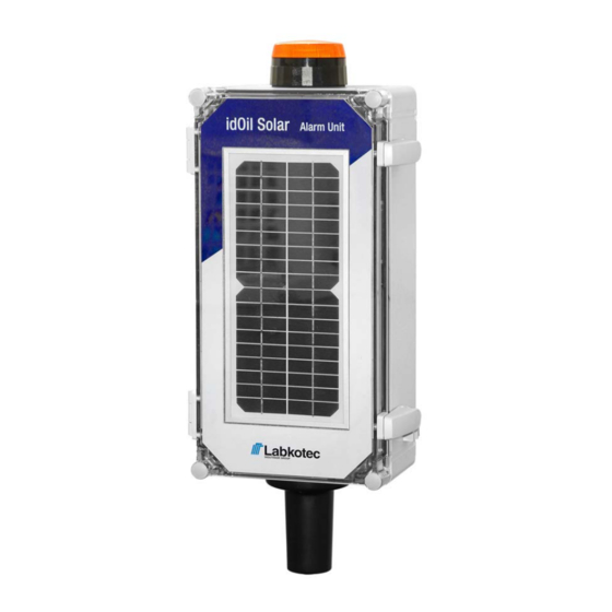
Product description 3.1. General The idOil Solar is a solar-powered alarm and communication unit for monitoring the levels of liquid hydrocarbon, sludge, or high levels in oil and sand separators, in locations where mains power is unavailable. This user manual includes installation and operating instructions for the following idOil Solar... -
Page 8: Device Operation
In case of an alarm, idOil Solar will either initiate a flashing beacon, or sends a text message (SMS) to pre-set phone numbers, or both. All alarms are also visible locally, in the idOil Solar Control Unit, during the short wake-up period. -
Page 9: Idoil-30 Battery Control Unit
Installation and Operating Instructions | idOil Solar 9/58 The idOil Solar will function for at least 6 months without any sunlight. When the idOil Solar is equipped with a xenon beacon, the operational time will be much less in case of an alarm (see Xenon beacon below). -
Page 10: Idoil-Oil Oil Sensor
Installation and Operating Instructions | idOil Solar 10/58 3.3.3. idOil-OIL Oil Sensor The idOil-OIL oil sensor is installed into the light liquid storage chamber and gives an alarm when the chamber is filled to a pre-determined level. The sensor is normally fully immersed in water. -
Page 11: Idoil-Liq High Liquid Level Sensor
The beacon is mounted on the top of the idOil Solar enclosure. The beacon is IP67 rated. In case of an alarm, the idOil Solar can operate the flashing the beacon for about 10 days with no sun-light, before the battery becomes discharged. In practise, there is always some solar power available, so the idOil Solar may function much longer with no interruption. -
Page 12: Installation
4.1. Installing idOil Solar Control Unit idOil Solar control unit can be wall mounted or installed on a pedestal. The enclosure has mounting holes at each of the corners beneath the mounting holes of the front cover. For pedestal installation, idOil Solar is equipped with a connector flange (see Appendix Connector Flange). -
Page 13: Installing The Idoil-Oil Sensor
Installation and Operating Instructions | idOil Solar 13/58 1 idOil-LIQ high liquid level sensor A Air B Oil C Water L Standard liquid level S Sensor switching point Liquid alarm limit (maximum surface level) Figure 6. Installing the idOil-LIQ high liquid limit sensor 4.2.2. - Page 14 Installation and Operating Instructions | idOil Solar 14/58 The sensor must always be immersed in liquid. The alarm is activated when the sludge layer reaches the alarm switching point (S), which is located inside the sensor gap (T). The sensor activates the alarm when it is in contact with air. For this reason, the separator must always be filled with water after draining.
-
Page 15: Connections
Installation and Operating Instructions | idOil Solar 15/58 Connections Read Section General safety instructions before installation. Make the connections when the device is de-energised. The legends for the connection diagrams can be found in the section following the diagrams. 5.1. -
Page 16: Connection With A Two-Sensor Cable Connector
Installation and Operating Instructions | idOil Solar 16/58 5.1.2. Connection with a two-sensor cable connector Figure 10. Connection with a two-sensor cable connector DOC001599-EN-3... -
Page 17: Connection With A Three-Sensor Cable Connector
Installation and Operating Instructions | idOil Solar 17/58 5.1.3. Connection with a three-sensor cable connector Figure 11. Connection with a three-sensor cable connector 5.2. Explanations of connection diagrams Supply voltage 11–17 V DC (N.B. The device does not include a mains switch, see Section General safety... - Page 18 Installation and Operating Instructions | idOil Solar 18/58 Relay outputs RELAY 1 = Relay common contact = Contact that opens in an alarm situation = Contact that closes in an alarm situation RELAY 2 = Relay common contact = Contact that opens in an alarm situation...
-
Page 19: Commissioning
APPENDIX; Factory settings for idOil Solar. idOil Solar must be activated in order to commission the system. This is done by pushing the Test and reset button of idOil-30 Control Unit for 10 seconds. Power switch must be 6.1. - Page 20 Installation and Operating Instructions | idOil Solar 20/58 The control unit display shows the message "Detecting sensors, 0 sensor(s) found" and three dots begin cycling at the bottom of the display. Figure 15. Sensor identification. Depending on how many sensors are...
-
Page 21: Commissioning Through The Browser-Based User Interface
Installation and Operating Instructions | idOil Solar 21/58 SIM card installation (idOil-30 3G model only, option). Ensure that the device is de-energised. Open the cover of the control unit and ensure that the connection protection plate is in place! Pull the SIM-holder (2) out from 3G module and install nano-SIM (1) to holder. -
Page 22: Establishing A Wlan Connection
Installation and Operating Instructions | idOil Solar 22/58 6.2.1. Establishing a WLAN connection Connect power to the idOil control unit. The display presents the message shown in the figure: NO SENSORS. Press the reset button briefly. A symbol indicating a WLAN network connection is shown in the upper left corner of the display. -
Page 23: System Settings
Installation and Operating Instructions | idOil Solar 23/58 6.2.2. System settings The System settings view shown in the figure is opened in the browser. Figure 22. System settings Do the following: 1. Select the desired language as the active language. The default is English. -
Page 24: Sensor Naming And Identification
Installation and Operating Instructions | idOil Solar 24/58 6.2.3. Sensor naming and identification Once the system settings have been set, the control unit switches to sensor identification mode and requests a password as shown in the figure. Figure 23. Sensor identification; enter password Enter 1234 in the password field and press the Login button. - Page 25 Installation and Operating Instructions | idOil Solar 25/58 Figure 25. Sensor identifications; sensors found If necessary, enter identifiers for the sensors in the Description field and press the Save button. If the control unit does not identify all connected sensors.
- Page 26 Installation and Operating Instructions | idOil Solar 26/58 Figure 26. Sensor identification, stop detection Once all connected sensors have been identified and individual descriptions have been provided for them: Press the home screen button in the upper left corner: The idOil separator alarm system is now operational at factory settings.
-
Page 27: Operation
After installation and commissioning, the idOil separator alarm system functions entirely independently and does not require constant monitoring. The idOil Solar is fully deactivated for most of the time, which means that it consumes very little power. The device only starts at set measurement intervals to perform the sensor measurements. -
Page 28: Resetting An Alarm
Installation and Operating Instructions | idOil Solar 28/58 7.2. Resetting an alarm An alarm can be reset by pressing the test button in the cover. Resetting an alarm deactivates the buzzer. However, the buzzer is always reactivated for 10 s every 24 hours until the cause for the alarm is eliminated. -
Page 29: Menu List
Installation and Operating Instructions | idOil Solar 29/58 idOil Type name of the control unit 2017-01-04 Date and time of the device's internal clock 16:45 Home screen button; by clicking this icon, you can return to the home screen Menu Selection of menu options Settings menu. -
Page 30: Alarm Log
Installation and Operating Instructions | idOil Solar 30/58 Figure 28. Menu list 7.3.2.1. Alarm log The alarm log records the times of the alarm and fault situations, the reset times, and the times at which the alarms and faults are eliminated. The following events are recorded in the alarm log: Sensor alarm situation. -
Page 31: Inspection
Installation and Operating Instructions | idOil Solar 31/58 Figure 29. Alarm log 7.3.2.2. Inspection This function adds an inspection measure in the device's inspection log. Recording inspection measures resets the inspection counter. Press the Start inspection button to activate the inspection form. -
Page 32: Inspection Log
Installation and Operating Instructions | idOil Solar 32/58 Figure 30. Inspection The inspection can also be conducted as a quick operation without using the browser user interface. When the inspection alarm is active, the inspection can be conducted with the test operation (see Test function). -
Page 33: Language
Installation and Operating Instructions | idOil Solar 33/58 Figure 31. Inspection log 7.3.2.4. Language You can select one of the supported languages in the Language menu. Select the desired language and press the Select button. This will change the language of the browser interface and local display to the selected language. -
Page 34: Date And Time
Installation and Operating Instructions | idOil Solar 34/58 Figure 32. Language selection 7.3.2.5. Date and time The control unit's date, time, time zone and automatic daylight saving setting can be set and updated in this view. Make the necessary changes and press the Save button. -
Page 35: Customer Data
Installation and Operating Instructions | idOil Solar 35/58 Figure 34. Password prompt Enter the password and press the Login button. The Settings menu features the functions shown in the figure below. The functions are described in more detail in the following paragraphs. -
Page 36: Inspection Settings
Installation and Operating Instructions | idOil Solar 36/58 Figure 36. Customer data 7.3.3.2. Inspection settings In the Inspection settings menu, you can set the inspection period counter. You can select between: never (factory setting, inspection period not used) 1 month... -
Page 37: Alarm Settings
Installation and Operating Instructions | idOil Solar 37/58 7.3.3.3. Alarm settings In the Alarm settings menu, you can change the following alarm settings: Alarm buzzer: Off/On. If Off is selected, the buzzer will not sound upon an alarm. Alarm repeat (24 h): Off/On. If On is selected, the alarm will be repeated 24 hours after a reset, if the cause of the alarm has not been eliminated. - Page 38 Installation and Operating Instructions | idOil Solar 38/58 Figure 39. Relay settings DOC001599-EN-3...
-
Page 39: Software Update
Installation and Operating Instructions | idOil Solar 39/58 7.3.3.5. Software update The software of the control unit can be updated through the user interface. The Software update menu shows the current software version and the available language options. Figure 40. Software update Upload the new software as follows: Press the Upload new software package button. -
Page 40: Restoring Factory Settings
Installation and Operating Instructions | idOil Solar 40/58 Figure 42. Software uploaded to the control unit Press the Update button. The software update begins and the message in the figure below is shown in the display. The various phases of the software update are presented in the control unit display. -
Page 41: Wlan Settings
Installation and Operating Instructions | idOil Solar 41/58 You can restore the factory settings as follows: Check the Restore factory settings box and press the Restore settings button (see the next figure). Figure 44. Restoring factory settings Confirm the restoration of the factory settings by pressing Yes, I want to clear all data button. -
Page 42: Low Power Mode Settings
Installation and Operating Instructions | idOil Solar 42/58 Figure 46. WLAN settings Establish the WLAN connection again according to the instructions in the Establishing a WLAN connection section. 7.3.3.8. Low power mode settings The following settings can be set in the Low power mode settings menu:... - Page 43 Installation and Operating Instructions | idOil Solar 43/58 Off/On: The flashing function of the idOil device's display backlight can be deactivated to save power. Battery voltage monitoring: Battery voltage level: Battery voltage value in volts Monitoring: Off/On. Battery low voltage alarm: The voltage limit below which the idOil device triggers a battery voltage alarm.
-
Page 44: Settings (Idoil-30 3G Model Only, Option)
Frequency: this sets the interval at which the idOil device sends a situation report to the set recipient phone numbers. Sending time: this sets the time at which the situation report should be sent. LabkoNet Enable LabkoNet service: Off/On To activate the LabkoNet service, please contact the Labkotec Oy customer service (info@labkotec.fi). DOC001599-EN-3... -
Page 45: Operating Idoil Solar With Mobile Phone
Operating idOil Solar with mobile phone This chapter is relevant to idOil Solar versions with 3G functionality only. After commissioning the idOil Solar system and installing a SIM card to 3G modem, the user is able to send text messages to the system. -
Page 46: Name Of The Device Or Location (Name)
Installation and Operating Instructions | idOil Solar 46/58 TEL <device name if specified> 1: <memory slot 1 telephone no> 5: <memory slot 5 telephone no> Example: If the device name has not been defined, no numbers have been set and the entered... -
Page 47: Time (Clock)
Installation and Operating Instructions | idOil Solar 47/58 7.4.3. Time (CLOCK) The time setting is needed if you wish to save log information with actual time stamps or if you want the device to send timed messages to the end user or the LabkoNet server. -
Page 48: Measurement Interval (Mi)
Installation and Operating Instructions | idOil Solar 48/58 Send the following message to the idOil device: TXD 1 12:00 Device response: TXD <device name> 1 12:00 The device sends a timed message every day at 12:00. Example 2 Switching off the timed message... -
Page 49: Listening Interval (Li)
Installation and Operating Instructions | idOil Solar 49/58 7.4.6. Listening interval (LI) A listening interval can be set for the device, according to which it will wake up from power saving mode, activate the 3G modem and read any possible setting messages and queries that have been sent to it. -
Page 50: Alarm Information Query (M)
Installation and Operating Instructions | idOil Solar 50/58 VLIM 11.8 The response is: VLIM Pirkkala Myllyhaantie 11.8 V 7.4.8. Alarm information query (M) To request alarm information from the device, send the following message to the idOil device: The device responds as described below by sending the device name, sensor names and alarm or fault information. -
Page 51: Test Idoil Solar Functions With The Sensors
When sensor is connected and totally immersed in water, idOil Solar should reply: “STATUS Airport ABC System OK” When sensor is connected and it is either immersed in oil or in air, idOil Solar should reply: “STATUS Airport ABC Oil level alarm 2018-07-13 15:20”... -
Page 52: Maintenance
Installation and Operating Instructions | idOil Solar 52/58 Maintenance The operation of the separator system and alarm device must be checked at least every 6 months by experienced personnel. The following is recommended in conjunction with the inspection: functional check of the idOil alarm device with the test function and sensor (see Section... -
Page 53: Maintenance Measures
Installation and Operating Instructions | idOil Solar 53/58 8.2. Maintenance measures The sensors must be cleaned in conjunction with maintenance inspections. You can clean the sensors with washing up liquid and a washing up brush, for example. Do not use corrosive substances to clean the sensors. -
Page 54: Technical And Safety Data
Installation and Operating Instructions | idOil Solar 54/58 Technical and safety data TECHNICAL SPECIFICATIONS idOil Solar alarm unit Dimensions 200 mm x 400 mm x 132 mm (w x h x d) Enclosure Material: polycarbonate IP rating: IP43 with two ventilation devices... -
Page 55: Appendices
10.1. Factory settings for idOil Solar Every idOil Solar alarm unit has the following settings pre-defined in the factory. The Low power settings of idOil Solar can be changed from idOil-30 Control Unit's settings either through the web user interface or by text messages:... -
Page 56: Connector Flange For Idoil Solar
Installation and Operating Instructions | idOil Solar 56/58 10.2. Connector Flange for idOil Solar 1. M6 x 8 mm locking screw 2. Connector flange 3. Mounting pipe Drill a 5 - 6 mm hole throught the mounting pipe (3) to ensure the idOil Solar is in its correct position. -
Page 57: Idoil Solar Wiring Diagram
Installation and Operating Instructions | idOil Solar 57/58 10.3. idOil Solar Wiring Diagram DOC001599-EN-3... -
Page 58: Idoil Solar Eu Declaration Of Conformity
Installation and Operating Instructions | idOil Solar 58/58 10.4. idOil Solar EU Declaration of Conformity DOC001599-EN-3...
Need help?
Do you have a question about the idOil Solar and is the answer not in the manual?
Questions and answers