Table of Contents
Advertisement
Advertisement
Table of Contents

Subscribe to Our Youtube Channel
Related Manuals for Labkotec OMS-1


Summary of Contents for Labkotec OMS-1
- Page 1 FI-33960 PIRKKALA FINLAND Tel: +358 29 006 260 Fax: +358 29 006 1260 8.8.2019 Internet: www.labkotec.com D15530_E-5 1/13 OMS-1 Oil Separator Alarm Device Installation and Operating Instructions Copyright © 2019 Labkotec Oy We reserve the right for changes without notice...
-
Page 2: Table Of Contents
Installation and Operating Instructions TABLE OF CONTENTS 1 GENERAL ......................3 2 INSTALLATION ....................4 2.1 OMS-1 control unit ..................4 2.2 OMS sensor ....................5 2.3 Cable joint ....................5 3 OPERATION ......................6 3.1 Modes of operation ..................6 4 TROUBLE-SHOOTING .................. -
Page 3: General
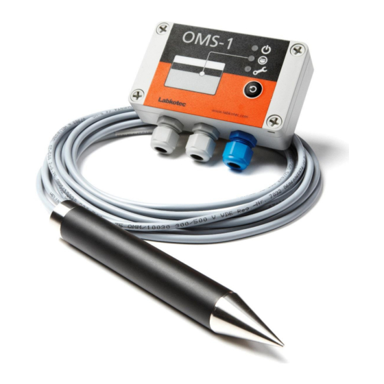
D15530_E-5 Installation and Operating Instructions GENERAL OMS-1 is an alarm device for monitoring the thickness of the oil layer accumulating in an oil separator. The system consists of OMS-1 control unit, OMS sensor and a cable joint. Figure 1. Oil separator supervision with OMS-1 alarm device OMS sensor is installed into the light liquid storage chamber and gives an alarm when the chamber oil layer reaches a pre-determined level. -
Page 4: Installation
Installation and Operating Instructions INSTALLATION OMS-1 control unit OMS-1 control unit can be wall-mounted. The mounting holes are located in the base plate of the enclosure, beneath the mounting holes of the front cover. The connectors of the external conductors are isolated by separating plate. -
Page 5: Oms Sensor
3. If shielded cable is used cable shields and possible excess wires need to be connected to the same point in galvanic contact. Please make sure, that the sensor and cable between OMS-1 control unit and the sensor do not exceed the maximum allowed electrical parameters –... -
Page 6: Operation
OMS-1 Oil Separator Alarm Device D15530_E-5 Installation and Operating Instructions OPERATION The operation of the alarm device should be checked always after the installation. Also check the operation always when emptying the separator or at least once every six months. - Page 7 TEST FUNCTION Test function provides an artificial alarm, which can be used to test the function of the OMS-1 alarm device and the function of other equipment, which are connected to OMS-1 via its relay. Attention! Before pressing the Reset/Test button, make sure that the...
-
Page 8: Trouble-Shooting
3. If it is possible measure also resistance between [+] wire and sensor’s upper electrode. The measured resistance should be 1,1 – 1,3 kΩ. 4. If the resistance values in items 2 and 3 are correct, then OMS-1 control unit is defective, otherwise problem is in cabling or in sensor. -
Page 9: Repair And Service
In case of queries, please contact Labkotec Oy’s service. SAFETY INSTRUCTIONS OMS-1 control unit must not be installed in potentially explosive atmosphere. Sensors connected to it may be installed in zone 0, 1 or 2 potentially explosive atmospheres. -
Page 10: Technical Data
YY = manufacturing year on the type plate (e.g. 19 = 2019) In the cable parameters of OMS-1 sensor connection must be taken into account the interaction of capacitance and inductance. The table below indicates the connecting values in explosion group IIB. -
Page 11: Appendix 1. Oms System Drawing
APPENDIX 1. OMS System drawing... -
Page 12: Appendix 2. Eu Declaration Of Conformity
APPENDIX 2. EU DECLARATION OF CONFORMITY... -
Page 13: Appendix 3. Eu Declaration Of Conformity
APPENDIX 3. EU DECLARATION OF CONFORMITY...
Need help?
Do you have a question about the OMS-1 and is the answer not in the manual?
Questions and answers