
Related Manuals for Labkotec idOil-20


Summary of Contents for Labkotec idOil-20
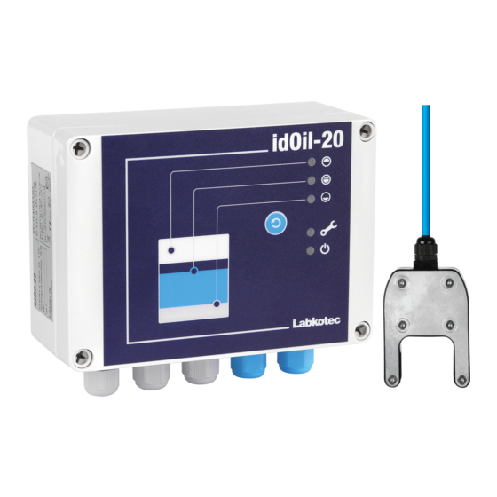
- Page 1 Installation and Operating Instructions ® idOil Oil Separator Alarm Device DOC001600-EN-5 10/12/2018...
-
Page 2: Table Of Contents
Installation and Operating Instructions | idOil-20 2/34 Table of contents 1. General information about the manual ........... - Page 3 Installation and Operating Instructions | idOil-20 3/34 8.2. Maintenance measures ........... . .
-
Page 4: General Information About The Manual
All of our products have been designed and manufactured with due consideration to the essential European standards, statutes and regulations. Labkotec Oy has a certified ISO 9001 quality management system and ISO 14001 environmental management system. 1.3. -
Page 5: Safety And The Environment
The device must be used in accordance with the instructions provided in this document. Other use is counter to the product’s purpose of use. Labkotec cannot be held liable for any damage caused by using the device in violation of its purpose of use. -
Page 6: Repair
Installation and Operating Instructions | idOil-20 6/34 If the temperature in the installation environment is expected to exceed +40°C, the temperature tolerance of the supply voltage and relay connection cable must be at least +80°C. Otherwise, any cable that meets the applicable electrical regulations can be used as the supply voltage and relay connection cable. -
Page 7: Product Description
Installation and Operating Instructions | idOil-20 7/34 Product description 3.1. Device operation ® idOil is an alarm system intended for monitoring liquid levels particularly in oil and sand separators. The system consists of the idOil control unit and the idOil sensors installed in the separator. -
Page 8: Products
Installation and Operating Instructions | idOil-20 8/34 3.2. Products Control unit: Type name Description idOil -20 Control unit, 100-240 V AC Sensors: Type name Description idOil -LIQ High liquid level sensor to sense excessively high liquid level idOil -OIL Oil sensor to detect the thickness of the oil layer... -
Page 9: Dimensions Idoil-Liq High Liquid Level Sensor
Installation and Operating Instructions | idOil-20 9/34 3.3.2. Dimensions idOil-LIQ high liquid level sensor A Sensor’s sensing element S Alarm switching point Figure 3. High liquid level sensor idOil-LIQ – structure and dimensions (mm) 3.3.3. Dimensions of the idOil-OIL oil sensor... -
Page 10: Dimensions Idoil-Slu Sludge Sensor
Installation and Operating Instructions | idOil-20 10/34 3.3.4. Dimensions idOil-SLU sludge sensor T Sensor gap S Alarm trigger point Figure 5. Sludge sensor idOil-SLU – structure and dimensions (mm) DOC001600-EN-5... -
Page 11: Installation
Installation and Operating Instructions | idOil-20 11/34 Installation 4.1. Installing the control unit The idOil control unit is wall mounted. Installation holes are located at the bottom part of the box under the mounting holes for the cover. The cover of the box must be tightened so that the edge touches the bottom part. This ensures that the reset and test button functions well and the enclosure is tight. -
Page 12: Installing The Idoil-Liq High Liquid Level Sensor
Installation and Operating Instructions | idOil-20 12/34 Suspension hook 2 Cable tie Figure 8. Sensor mounting supplies Figure 7. Sensor suspension example LMS-SAS5 4.2.1. Installing the idOil-LIQ high liquid level sensor The sensor is normally in air, and it issues an alarm when the sensing element is submerged in liquid. -
Page 13: Installing The Idoil-Slu Sludge Sensor
Installation and Operating Instructions | idOil-20 13/34 The sensor activates the alarm when it is in contact with air. For this reason, the separator must always be filled with water after draining. 1 idOil-OIL oil sensor A Air B Oil... -
Page 14: Connections
Installation and Operating Instructions | idOil-20 14/34 Connections Read Section General safety instructions before installation. Make the connections when the device is de-energised. The legends for the connection diagrams can be found in the section following the diagrams. 5.1. Connection diagrams 5.1.1. -
Page 15: Connection With A Two-Sensor Cable Connector
Installation and Operating Instructions | idOil-20 15/34 5.1.2. Connection with a two-sensor cable connector Figure 13. Connection with a two-sensor cable connector 5.1.3. Connection with a three-sensor cable connector Figure 14. Connection with a three-sensor cable connector DOC001600-EN-5... -
Page 16: Explanations Of Connection Diagrams
Installation and Operating Instructions | idOil-20 16/34 5.2. Explanations of connection diagrams Supply voltage 100–240 V AC (N.B. The device does not include a mains switch, see Section General safety instructions) = protective earth connector = neutral connector = phase connector UL/CSA: Supply cable 3 x 1,5-2,1 mm (AWG16-AWG14). - Page 17 Installation and Operating Instructions | idOil-20 17/34 Protection plate The connectors for the external connections are separated with separator walls on the protection plate. The separator walls must not be removed. The protection plate covering the connectors must be reinstalled after connecting the cables.
-
Page 18: Commissioning
Installation and Operating Instructions | idOil-20 18/34 Commissioning 6.1. Sensor identification Ensure that the sensors have been installed and connected in the control unit in accordance with the instructions in the previous paragraphs. DANGER OF ELECTRICAL SHOCK! Please observe the safety... -
Page 19: Factory Settings Of The Idoil Control Unit
Installation and Operating Instructions | idOil-20 19/34 6.2. Factory settings of the idOil control unit Alarm buzzer Alarm repeat (24h) Alarm settings Alarm delay for all sensors 10 s Alarm reset button All sensors connected to the Connected sensors control unit... -
Page 20: Operation
Installation and Operating Instructions | idOil-20 20/34 Operation After installation and commissioning, the idOil separator alarm system functions entirely independently and does not require constant monitoring. The alarm information can be connected to automation systems through relays. All of the system’s connections and functions are described in the figure below and in more detail in the following sections. - Page 21 Installation and Operating Instructions | idOil-20 21/34 Normal situation The level of the liquid being measured is below the high level sensor (idOil-LIQ), the oil sensor (idOil-OIL) is in water and the sludge sensor (idOil-SLU) is in water. The indicator lights for voltage supply, sensor alarms and faults are green.
-
Page 22: Resetting An Alarm
Installation and Operating Instructions | idOil-20 22/34 7.2. Resetting an alarm An alarm can be reset by pressing the test button in the cover. Resetting an alarm deactivates the buzzer. However, the buzzer is always reactivated for 10 s every 24 hours until the cause for the alarm is eliminated. -
Page 23: Maintenance
Installation and Operating Instructions | idOil-20 23/34 Maintenance The operation of the separator system and alarm device must be checked at least every 6 months by experienced personnel. The following is recommended in conjunction with the inspection: functional check of the idOil alarm device with the test function and sensor (see Section... -
Page 24: Maintenance Measures
(+ or -) makes no difference. EXPLOSION HAZARD! Observe the installation and maintenance instructions for explosive atmospheres! The measuring device must be Exi classified if the sensor is in an explosive area. If problems occur, contact Labkotec Oy's service department. DOC001600-EN-5... -
Page 25: Technical Specifications
Installation and Operating Instructions | idOil-20 25/34 Technical specifications 9.1. Technical specifications for the idOil control unit TECHNICAL SPECIFICATIONS idOil-20 Dimensions 175 mm x 125 mm x 75 mm (w x h x d) Enclosure IP 65, material: polycarbonate Weight... -
Page 26: Technical Specifications Idoil-Liq High Liquid Level Sensor
Installation and Operating Instructions | idOil-20 26/34 9.2. Technical specifications idOil-LIQ high liquid level sensor TECHNICAL SPECIFICATIONS idOil-LIQ Operating principle Vibration Enclosure Enclosure class: IP 68 Materials: PVC, aluminium, PA, CR, Viton Weight 300 g (incl. 5 m cable) Temparature Operation: 0ºC…+60ºC... -
Page 27: Technical Specifications Idoil-Slu Sludge Sensor
Installation and Operating Instructions | idOil-20 27/34 ATEX and IECEx VTT 17 ATEX 004X IECEx VTT 17.0002X Ex classification II 1 G Ex ia IIA T5 Ga Special terms (X) Ta = -39°C…+60°C Exi connection values Ui = 16 V, Ii = 80 mA, Po = 400 mW Maximum values in explosion group IIB Ci <... -
Page 28: Appendices
Installation and Operating Instructions | idOil-20 28/34 Appendices 10.1. APPENDIX A System digram DOC001600-EN-5... - Page 29 Installation and Operating Instructions | idOil-20 29/34 DOC001600-EN-5...
- Page 30 Installation and Operating Instructions | idOil-20 30/34 DOC001600-EN-5...
-
Page 31: 10.2. Appendix B Eu Declaration Of Conformity
Installation and Operating Instructions | idOil-20 31/34 10.2. APPENDIX B EU Declaration of Conformity DOC001600-EN-5... - Page 32 Installation and Operating Instructions | idOil-20 32/34 DOC001600-EN-5...
- Page 33 Installation and Operating Instructions | idOil-20 33/34 DOC001600-EN-5...
- Page 34 Installation and Operating Instructions | idOil-20 34/34 DOC001600-EN-5...
Need help?
Do you have a question about the idOil-20 and is the answer not in the manual?
Questions and answers