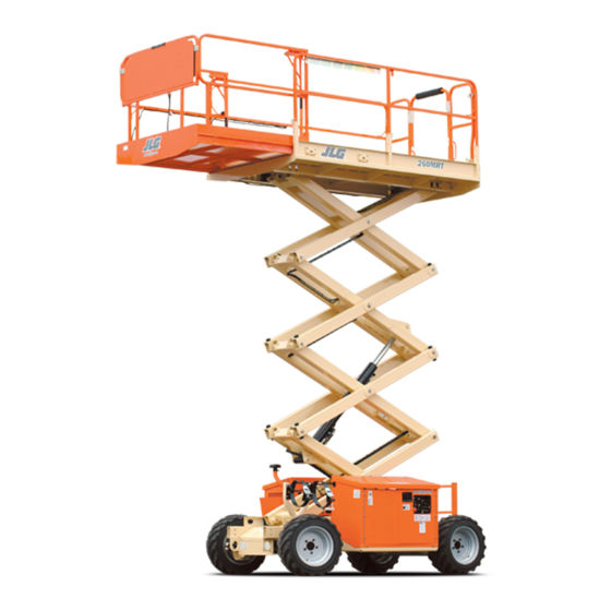
JLG 260MRT Operation And Safety Manual
Hide thumbs
Also See for 260MRT:
- Service and maintenance manual (107 pages) ,
- Operation and safety manual (92 pages) ,
- Quick start manual (9 pages)

Related Manuals for JLG 260MRT


Summary of Contents for JLG 260MRT
- Page 1 Operation and Safety Manual Original Instructions - Keep this manual with the machine at all times. Model 260MRT PVC 1910 ANSI AS/NZS 31215865 November 6, 2019 - Rev A ®...
- Page 2 @ www.discount-equipment.com Select an option below to find your Equipment We sell worldwide for the brands: Genie, Terex, JLG, MultiQuip, Mikasa, Essick, Whiteman, Mayco, Toro Stone, Diamond Products, Generac Magnum, Airman, Haulotte, Barreto, Power Blanket, Nifty Lift, Atlas Copco, Chicago Pneumatic, Allmand, Miller Curber, Skyjack, Lull,...
- Page 3 WARNING Operating, servicing and maintaining this vehicle or equipment can expose you to chemicals including engine exhaust, carbon monoxide, phthalates, and lead, which are known to the State of California to cause cancer and birth defects or other reproductive harm. To minimize exposure, avoid breathing exhaust, do not idle the engine except as necessary, service your vehicle or equipment in a well-ventilated area and wear gloves or wash your hands frequently when servicing.
- Page 4 The purpose of this manual is to provide owners, users, operators, lessors, and lessees with the precautions and operating procedures essential for the safe and proper machine operation for its intended purpose. Due to continuous product improvements, JLG Industries, Inc. reserves the right to make specification changes without prior notification. Contact JLG Industries, Inc. for updated information.
- Page 5 FOREWORD SAFETY ALERT SYMBOLS AND SAFETY SIGNAL WORDS THIS IS THE SAFETY ALERT SYMBOL. IT IS USED TO ALERT YOU TO THE POTENTIAL PERSONAL INJURY HAZARDS. OBEY ALL SAFETY MESSAGES THAT FOLLOW THIS SYMBOL TO AVOID POSSIBLE INJURY OR DEATH. INDICATES A POTENTIALITY HAZARDOUS SITUATION.
- Page 6 FOREWORD REVISION LOG Original Issue A - November 6, 2019 31215865...
-
Page 7: Table Of Contents
TABLE OF CONTENTS SECTION - 1 - SAFETY PRECAUTIONS PRE-START INSPECTION ......2-4 WALK-AROUND INSPECTION . - Page 8 TABLE OF CONTENTS Starting Procedure ....... . 4-3 Post-Incident Inspection......5-3 OPERATING CHARACTERISTICS .
- Page 9 TABLE OF CONTENTS LIST OF TABLES Wheel Installation ....... 7-12 SUPPLEMENTAL INFORMATION .
-
Page 10: Section 1. Safety Precautions
JLG Industries, • Only personnel who have received proper training regarding Inc. (“JLG”). -
Page 11: Workplace Inspection
WRITTEN PERMISSION FROM THE MANUFACTURER trailers, railway cars, floating vessels, scaffolds or other equip- ment unless the application is approved in writing by JLG. • Do not operate any machine on which the safety or instruction placards or decals are missing or illegible. -
Page 12: Operation
SECTION 1 - SAFETY PRECAUTIONS OPERATION • Do not carry materials directly on platform railing unless approved by JLG. General • When two or more persons are in the platform, the operator shall be responsible for all machine operations. • Machine operation requires your full attention. Bring the •... -
Page 13: Trip And Fall Hazards
• Prior to operation, ensure all gates and rails are fastened and secured in their proper position. • JLG Industries, Inc. recommends that all persons in the plat- form wear a full body harness with a lanyard attached to an •... -
Page 14: Electrocution Hazards
SECTION 1 - SAFETY PRECAUTIONS Electrocution Hazards • This machine is not insulated and does not provide protection from contact or proximity to electrical current. • Maintain safe clearance from electrical lines, apparatus, or any energized (exposed or insulated) parts in accordance with the •... -
Page 15: Tipping Hazards
(Phase to Phase) in Feet (Meters) the platform. Keep all loads within the confines of the plat- form, unless authorized by JLG. 0 to 50KV 10 (3) • Keep the chassis of the machine a minimum of 0.6 m (2 ft) - Page 16 SECTION 1 - SAFETY PRECAUTIONS DO NOT OPERATE THE MACHINE WHEN WIND CONDITIONS EXCEED SPECIFICATIONS SHOWN IN SECTION 7.2 OR AS SHOWN ON THE CAPACITY PLACARD ON THE PLAT- FORM BILLBOARD. Table 1-2. Beaufort Scale (For Reference Only) Wind Speed Beaufort Description Land Conditions...
- Page 17 SECTION 1 - SAFETY PRECAUTIONS • Never attempt to use the machine as a crane. Do not tie-off machine to any adjacent structure. Never attach wire, cable, or any similar items to platform. • If scissor arm assembly or platform is caught so that one or more wheels are off the ground, all persons must be removed before attempting to free the machine.
-
Page 18: Crushing And Collision Hazards
SECTION 1 - SAFETY PRECAUTIONS Crushing and Collision Hazards • Be aware of stopping distances in all drive speeds. When driv- ing in high speed, reduce drive speed before stopping. Travel grades in low speed only. • Approved head gear must be worn by all operating and ground personnel. -
Page 19: Towing, Lifting, And Hauling
SECTION 1 - SAFETY PRECAUTIONS TOWING, LIFTING, AND HAULING MAINTENANCE • Never allow personnel in platform while towing, lifting, or General hauling. • This machine should not be towed, except in the event of This section contains general safety precautions which must be emergency, malfunction, power failure, or loading/unloading. -
Page 20: Battery Hazards
• Use only replacement parts or com- batteries. Ensure that battery acid does not come in contact ponents that are approved by JLG. To be considered approved, with skin or clothing. replacement parts or components must be identical or equiva- lent to original parts or components •... - Page 21 SECTION 1 - SAFETY PRECAUTIONS NOTES: 1-12 31215865...
-
Page 22: Section 2 - User Responsibilities, Machine Preparation, And Inspection
SECTION 2 - USER RESPONSIBILITIES, MACHINE PREPARATION, AND INSPECTION SECTION 2. USER RESPONSIBILITIES, MACHINE PREPARATION, AND INSPECTION PERSONNEL TRAINING Selection of the appropriate MEWPs and available options for the work to be performed considering specific job requirements, with involvement from the MEWP owner, user, The Mobile Elevating Work Platform (MEWP) is a personnel han- and/or supervisor. -
Page 23: Machine Familiarization
Responsibilities for familiarization may vary by region. The following table covers the machine inspections and mainte- nance recommended by JLG Industries, Inc. Consult local regula- tions for further requirements for aerial work platforms. The Only properly trained personnel who have received unit-specific frequency of inspections and maintenance must be increased as familiarization shall operate a MEWP. -
Page 24: Inspection And Maintenance Table
NOTE: Inspection forms are available from JLG. Use the Service and Maintenance Manual to perform inspections. NOTICE JLG INDUSTRIES, INC. RECOGNIZES A FACTORY-TRAINED SERVICE TECHNICIAN AS A PERSON WHO HAS SUCCESSFULLY COMPLETED THE JLG SERVICE TRAINING SCHOOL FOR THE SPECIFIC JLG PRODUCT MODEL. -
Page 25: Pre-Start Inspection
Make sure all illegible decals and placards are cleaned or replaced. Lanyard Anchorage Points – JLG Industries, Inc. recom- mends personnel in the platform wear a full body harness Operation and Safety Manuals – Ensure a copy of the... -
Page 26: Walk-Around Inspection
SECTION 2 - USER RESPONSIBILITIES, MACHINE PREPARATION, AND INSPECTION WALK-AROUND INSPECTION 12,13 OAD01920 11, 12 31215865... - Page 27 SECTION 2 - USER RESPONSIBILITIES, MACHINE PREPARATION, AND INSPECTION Begin the Walk-Around Inspection at Item 1, as noted on the dia- Platform Controls - Properly secured, no loose or missing gram. Continue to the right (counterclockwise viewed from top) parts, no visible damage. Placards secure and legible, control checking each item in sequence for the conditions listed in the switches return to neutral when activated and released, following checklist.
- Page 28 SECTION 2 - USER RESPONSIBILITIES, MACHINE PREPARATION, AND INSPECTION Lift Cylinder - See Note. Ladder - No damage, securely attached. Fuel Tank (Gasoline or Diesel Engine) - Filler cap secure, Speed Cutout Switch - No visible damage, properly sight gauge visible, no damage or leaks. secured.
-
Page 29: Function Check
SECTION 2 - USER RESPONSIBILITIES, MACHINE PREPARATION, AND INSPECTION FUNCTION CHECK e. Ensure that all machine functions are disabled when the Emergency Stop Button is pushed in. Perform the Function Check as follows: f. Ensure all machine functions stop when function con- trol is released or when joystick trigger is released. -
Page 30: Dual Fuel System (If Equipped)
SECTION 2 - USER RESPONSIBILITIES, MACHINE PREPARATION, AND INSPECTION DUAL FUEL SYSTEM (IF EQUIPPED) Changing from LP Gas to Gasoline. With the engine operating on LP gas under a no load condi- tion, position the LPG/GAS SELECT switch at the platform control station to the GAS SELECT position. - Page 31 SECTION 2 - USER RESPONSIBILITIES, MACHINE PREPARATION, AND INSPECTION NOTES: 2-10 31215865...
-
Page 32: Section 3 - Machine Controls And Indicators
SECTION 3 - MACHINE CONTROLS AND INDICATORS SECTION 3. MACHINE CONTROLS AND INDICATORS GENERAL THE MANUFACTURER HAS NO DIRECT CONTROL OVER MACHINE APPLICATION AND OPERATION, THE USER AND OPERATOR ARE RESPONSIBLE FOR CONFORMING WITH GOOD SAFETY PRACTICES. This section provides the necessary information needed to understand machine controls and indicators. -
Page 33: Controls And Indicators
SECTION 3 - MACHINE CONTROLS AND INDICATORS CONTROLS AND INDICATORS Ground Control Station 1. Ground/Platform/OFF Key Selector Switch 2. Latch 3. Circuit Breaker 4. Alternator LED 5. Oil Pressure LED 6. Glow Plug Switch 7. Coolant Temperature LED 8. Hydraulic Charge Pressure LED 9. - Page 34 SECTION 3 - MACHINE CONTROLS AND INDICATORS NOTE: With the Power Selector switch in the off position, the key can be removed in order to incapacitate the machine on the jobsite to DO NOT OPERATE FROM GROUND CONTROL STATION WITH PERSONNEL IN THE PLAT- avoid unauthorized use of the machine.
- Page 35 SECTION 3 - MACHINE CONTROLS AND INDICATORS Charge Pressure - Illuminates when the charge pressure Emergency Stop Switch - A two-position, red, mushroom- shaped ignition/emergency stop switch, when positioned to drops below 70 psi (4.8 bar), indicating the charge filter is clogged and needs to be replaced.
-
Page 36: Platform Control Station
SECTION 3 - MACHINE CONTROLS AND INDICATORS Platform Control Station 1. Start Switch 2. Joystick Controller 3. Steer Control Switch 4. Speed/Generator Switch 5. Emergency Stop Switch 6. Lift Select Switch 7. Drive Select Switch 8. Horn 9. Trigger (Enable) Switch 10. - Page 37 SECTION 3 - MACHINE CONTROLS AND INDICATORS Start Switch - A momentary contact, push button type Speed/Generator Switch - The three position speed/gener- ator switch permits the operator to select either high range, switch that supplies electrical power to the starter solenoid when the emergency stop switch is in the on position and low range or the generator (if equipped).
- Page 38 SECTION 3 - MACHINE CONTROLS AND INDICATORS Emergency Stop Switch - A two-position, red, mushroom- Horn - This push-button switch, when activated, permits the operator to warn jobsite personnel when the machine is shaped emergency stop switch functions to provide power to the platform control station and also to turn off power to operating in the area.
-
Page 39: Platform Control Front Panel
SECTION 3 - MACHINE CONTROLS AND INDICATORS Platform Control Front Panel 1. Dual Fuel Selector Switch 2. Diesel Fuel Selector Switch 3. Leveling Jacks Switch (If Equipped) 31215865... - Page 40 SECTION 3 - MACHINE CONTROLS AND INDICATORS Fuel/Glow Plug Selector Switch - Selects which fuel source NOTE: There is an override feature on the Auto Leveling system that allows the operator to adjust (trim) the level of the machine to will be used.
-
Page 41: Indicator Panel Leds
SECTION 3 - MACHINE CONTROLS AND INDICATORS Indicator Panel LEDs Drive Lift Fuel Gauge Tilt Engine Distress Leveling Jacks (Retracted) Leveling Jacks (Set) 32 52 6 95 B 3-10 31215865... - Page 42 SECTION 3 - MACHINE CONTROLS AND INDICATORS Drive - This LED will illuminate when the drive select button Leveling Jacks (retracted) - This set of lights will illuminate once all the leveling jacks are retracted. is activated. Lift - This LED will illuminate when the lift select button is Leveling Jacks (extended) - This set of lights will illuminate activated.
-
Page 43: Decals
SECTION 3 - MACHINE CONTROLS AND INDICATORS DECALS ANSI, ANSI Export, CSA OAD01870 3-12 31215865... - Page 44 SECTION 3 - MACHINE CONTROLS AND INDICATORS 12 35 OAD01880 31215865 3-13...
- Page 45 SECTION 3 - MACHINE CONTROLS AND INDICATORS ANSI SPA, POR ENG, SPA ENG, FRE Item (0259792-N) (0259795-K) (0259794-K) (0272257-H) 1 - 6 1703816 1704699 1704691 1704684 1704138 1704138 1704138 1704138 1704529 1704529 1704529 1704529 1701509 1701509 1701509 1701509 1703811 1703811 1703811 1703811 1703812...
- Page 46 SECTION 3 - MACHINE CONTROLS AND INDICATORS ANSI SPA, POR ENG, SPA ENG, FRE Item (0259792-N) (0259795-K) (0259794-K) (0272257-H) 31 - 32 1705303 1705303 1001223055 1001224052 1001224049 1001223971 36 - 39 1001223453 1001223453 1001231801 31215865 3-15...
- Page 47 SECTION 3 - MACHINE CONTROLS AND INDICATORS CE, AUS OAD01890 3-16 31215865...
- Page 48 SECTION 3 - MACHINE CONTROLS AND INDICATORS OAD01900 31215865 3-17...
-
Page 49: Ce, Aus
SECTION 3 - MACHINE CONTROLS AND INDICATORS CE, AUS Item (0275087-G) CE, AUS Item 27 - 29 (0275087-G) 1704412 1 - 6 31 - 34 1704548 1702788 1704138 1701542 (Dual Fuel) 1704529 1701505 (Diesel) 1704559 1701509 1702773 1703811 1701435 1703812 1703814 1704277 1703819... -
Page 50: Section 4 - Machine Operation
SECTION 4 - MACHINE OPERATION SECTION 4. MACHINE OPERATION GENERAL DESCRIPTION This machine is a Mobile Elevating Work Platform (MEWP) used to position personnel, along with their necessary tools and materi- THE MANUFACTURER HAS NO DIRECT CONTROL OVER MACHINE APPLICATION AND als at work locations. - Page 51 @ www.discount-equipment.com Select an option below to find your Equipment We sell worldwide for the brands: Genie, Terex, JLG, MultiQuip, Mikasa, Essick, Whiteman, Mayco, Toro Stone, Diamond Products, Generac Magnum, Airman, Haulotte, Barreto, Power Blanket, Nifty Lift, Atlas Copco, Chicago Pneumatic, Allmand, Miller Curber, Skyjack, Lull,...
-
Page 52: Operating Characteristics And Limitations
Load is within manufacturer’s rated capacity. All machine systems are functioning properly. Stability This machine, as originally manufactured by JLG and operated within its rated capacity on a smooth, firm surface, within the lim- its of the maximum operating slope, provides a stable aerial plat- form for all platform positions. -
Page 53: Engine Operation
SECTION 4 - MACHINE OPERATION ENGINE OPERATION Starting Procedure Power Selector Switch NOTE: Initial starting should always be performed from the Ground Control Station. The power selector switch functions to direct electrical power to Check engine oil before attempting to start engine; if neces- the desired control station. -
Page 54: Operating Characteristics
SECTION 4 - MACHINE OPERATION OPERATING CHARACTERISTICS IF ENGINE FAILS TO START PROMPTLY, DO NOT CRANK FOR AN EXTENDED PERIOD. Leveling Jacks SHOULD ENGINE FAIL TO START ONCE AGAIN, ALLOW STARTER TO “COOL OFF” FOR 2 TO 3 MINUTES. IF ENGINE FAILS TO START AFTER SEVERAL ATTEMPTS, REFER TO The machine may be equipped with auto leveling jacks with a ENGINE MAINTENANCE MANUAL. -
Page 55: Manual Level Adjustment (Trim)
SECTION 4 - MACHINE OPERATION Manual Level Adjustment (Trim) Continue to engage the leveling jacks until the tilt light stops blinking and is no longer lit. NOTE: There is an override feature on the Leveling Jack system that NOTE: If you receive a 2/5 flash code through the system fault light at allows the operator to adjust (trim) the level of the machine to the platform control station the machine is unable to level. -
Page 56: Platform
SECTION 4 - MACHINE OPERATION PLATFORM Raising Platform Loading DO NOT RAISE PLATFORM EXCEPT ON A SMOOTH, FIRM, AND LEVEL SURFACE WITHIN The platform maximum rated load capacity is shown on a placard located on the platform billboard and ground control station and THE LIMITS OF THE MAXIMUM OPERATING SLOPE, FREE OF OBSTRUCTIONS AND HOLES. -
Page 57: Lowering
SECTION 4 - MACHINE OPERATION Lowering Platform Extension The machine is equipped with a mechanical extension deck, which adds 3 ft (0.9 m) to the front of the platform, giving the ENSURE SCISSOR ARM AREA IS FREE OF PERSONNEL PRIOR TO LOWERING PLATFORM. operator better access to work-sites. -
Page 58: Driving
SECTION 4 - MACHINE OPERATION DRIVING DIRECTION OF DRIVE AND STEER MOVEMENT MAY BE OPPOSITE FROM NOR-MAL OPERATION. BEFORE DRIVING, LOCATE THE BLACK/WHITE ORIENTA-TION ARROWS ON BOTH THE CHASSIS AND THE PLATFORM CONTROLS. MOVE THE DRIVE CONTROLS IN A DO NOT DRIVE WITH PLATFORM RAISED EXCEPT ON A SMOOTH, FIRM AND LEVEL DIRECTION MATCHING THE ORIENTATION ARROWS. -
Page 59: Steering
SECTION 4 - MACHINE OPERATION Steering Driving Forward To steer the machine, the thumb operated steer control switch on Place the power selector switch at the ground control sta- the controller handle is positioned to the right for traveling right, tion to platform. -
Page 60: Grade And Sideslope Depiction
SECTION 4 - MACHINE OPERATION LE V E L Figure 4-1. Grade and Sideslope Depiction 4-10 31215865... -
Page 61: Parking And Stowing
Chock at least two wheels when parking the machine for an NOTE: If lifting becomes necessary from the lifting lugs, Jlg Industries extended period of time. Inc. recommends the use of a proper spreader bar to avoid dam- Turn the power selector switch to off and remove the key to age to the machine. -
Page 62: 4.11 Towing
SECTION 4 - MACHINE OPERATION 4.11 TOWING Although towing the machine is prohibited, provisions for mov- USE EXTREME CAUTION WHEN OPENING THE TOW VALVE. THE DRIVE FUNCTION WILL ing the machine, in case of a malfunction or power failure, have STILL OPERATE WITH THE TOW VALVE OPEN, BUT THE BRAKE IS DISABLED. -
Page 63: Lifting Chart
SECTION 4 - MACHINE OPERATION WHEELBASE MODEL (in) (in) (in) 260MRT 41.5 28.5 Figure 4-2. Lifting Chart 31215865 4-13... -
Page 64: 4.12 Platform Rails - Fold-Down Procedure
SECTION 4 - MACHINE OPERATION 4.12 PLATFORM RAILS - FOLD-DOWN PROCEDURE To fold down each of the rails, remove the bail pins for that rail. Taking a firm hold on the top rail, carefully lower until the top rail is fully folded in the down position. ONLY FOLD DOWN THE RAILS WHEN THE MACHINE IS IN THE STOWED (PLATFORM FULLY LOWERED) POSITION. -
Page 65: Platform Rails - Fold Down Sequence - Front/Rear
SECTION 4 - MACHINE OPERATION Figure 4-3. Platform Rails - Fold Down Sequence - Front/Rear Rails 31215865 4-15... -
Page 66: Platform Rails - Fold Down Sequence - Deck Extension Side
SECTION 4 - MACHINE OPERATION Figure 4-4. Platform Rails - Fold Down Sequence - Deck Extension Side Rails 4-16 31215865... -
Page 67: Platform Rails - Fold Down Sequence - Main Platform Side
SECTION 4 - MACHINE OPERATION Figure 4-5. Platform Rails - Fold Down Sequence - Main Platform Side Rails 31215865 4-17... - Page 68 SECTION 4 - MACHINE OPERATION NOTES: 4-18 31215865...
-
Page 69: Section 5 - Emergency Procedures
SECTION 5 - EMERGENCY PROCEDURES SECTION 5. EMERGENCY PROCEDURES GENERAL This section explains the steps to be taken in case of an emer- gency situation during operation. Manual Descent The manual descent valve is used, in the event of total power fail- ure, to lower the platform using gravity. -
Page 70: Emergency Operation
SECTION 5 - EMERGENCY PROCEDURES EMERGENCY OPERATION Platform Caught Overhead If the platform becomes jammed or snagged in overhead struc- Use of Ground Controls tures or equipment, do the following: Shut off the machine. KNOW HOW TO USE THE GROUND CONTROLS IN AN EMERGENCY SITUATION. Rescue all people in the platform before freeing the machine. -
Page 71: Righting Of Tipped Machine
JLG Industries, Inc. must be notified immediately of any incident A forktruck of suitable capacity or equivalent equipment should involving a JLG product. Even if no injury or property damage is be placed under the elevated side of the chassis, with a crane or... - Page 72 SECTION 5 - EMERGENCY PROCEDURES NOTES: 31215865...
-
Page 73: Section 6 - Accessories
SECTION 6 - ACCESSORIES SECTION 6. ACCESSORIES Table 6-1. Available Accessories Market Accessory ANSI ANSI (USA Only) 1/2 Airline Platform Worklights Platform Rail Padding 31215865... -
Page 74: 1/2 Airline
SECTION 6 - ACCESSORIES 1/2 AIRLINE PLATFORM WORKLIGHTS The 1/2 Airline is a fitting for air-powered tools that is mounted in the platform. The Platform Worklights accessory consists of two 12V lights mounted to the platform railings. 31215865... -
Page 75: Platform Rail Padding
SECTION 6 - ACCESSORIES PLATFORM RAIL PADDING With Deck Bumpers OAD00050 1. Deck Bumpers Platform Rail Padding provides bumpers to the top plat- form rails in order to prevent damage to the platform itself This accessory is also available with proximity switches, as well as objects it may come into contact with during which attaches a padded frame to the bottom of the plat- operation. - Page 76 SECTION 6 - ACCESSORIES NOTES: 31215865...
-
Page 77: Section - 7 - General Specifications And Operator Mainte
SECTION 7 - GENERAL SPECIFICATIONS AND OPERATOR MAINTENANCE SECTION 7. GENERAL SPECIFICATIONS AND OPERATOR MAINTENANCE INTRODUCTION Other Publications Available Specific to this Machine: Service and Maintenance Manual........31215866 This section of the manual provides additional necessary infor- Illustrated Parts Manual ............31215867 mation to the operator for proper operation and maintenance of this machine. -
Page 78: Specifications
SECTION 7 - GENERAL SPECIFICATIONS AND OPERATOR MAINTENANCE SPECIFICATIONS Platform Lift Up Speed (No Load) Dual Fuel 25 - 29 seconds Operating Specifications Diesel 32 - 34 seconds Platform Lowering Speed (No Load) 21-27 seconds Maximum Platform Height 26 ft (8 m) Maximum Operating Hydraulic Pressure 3,300 psi (234 bar) Maximum Stowed Travel Grade (Gradeability) -
Page 79: Dimensional Data
SECTION 7 - GENERAL SPECIFICATIONS AND OPERATOR MAINTENANCE Dimensional Data Tires Size 26X12-15 Foam Filled Overall Height Stowed (Rails Up) Ply Rating Standard 96.16 in (2.44 m) Long Leveling Jacks Option (Australia Only) 97.41 ft (2.47 m) Inflation Pressure 55 psi (4 bar) Wheel Nut Torque 105 ft.lb. - Page 80 SECTION 7 - GENERAL SPECIFICATIONS AND OPERATOR MAINTENANCE Engine Kubota Diesel (D1005-E4B) Kubota Dual Fuel (WG752-GL-G3) Emissions CARB, EPA Tier 4 Final, and EU Stage V Diesel: Emissions CARB, EPA Phase 3 - Low Sulfur (<500 ppm) Gasoline - 87 Octane minium Fuel Type: - Ultra Low Sulfur (15 ppm) (Required to meet - Ethanol/Gas Mix-10% maximum...
-
Page 81: Lubrication
UTTO Fluid hydraulic oil, which has an SAE viscosity index of 152. NOTE: Aside from JLG recommendations, it is not advisable to mix oils of different brands or types, as they may not contain the same required additives or be of comparable viscosities. -
Page 82: Engine Operating Temperature Specifications (Kubota)
SECTION 7 - GENERAL SPECIFICATIONS AND OPERATOR MAINTENANCE 4150548_E DIESEL Figure 7-1. Engine Operating Temperature Specifications (Kubota)- Sheet 1 of 2 31215865... -
Page 83: Engine Operating Temperature Specifications (Kubota)
SECTION 7 - GENERAL SPECIFICATIONS AND OPERATOR MAINTENANCE 4150548_E Figure 7-2. Engine Operating Temperature Specifications (Kubota)- Sheet 2 of 2 31215865... -
Page 84: Operator Maintenance
SECTION 7 - GENERAL SPECIFICATIONS AND OPERATOR MAINTENANCE OPERATOR MAINTENANCE Safety Prop TO AVOID PERSONAL INJURY, THE SAFETY PROP MUST BE USED WHENEVER MAINTE- NANCE PERFORMED ON THE MACHINE REQUIRES THE SCISSOR ARMS TO BE RAISED. To engage the safety prop, with no load in the platform, raise the platform, then rotate the prop clockwise until it hangs vertically. -
Page 85: Inspection Check Points
SECTION 7 - GENERAL SPECIFICATIONS AND OPERATOR MAINTENANCE Inspection Check Points 1 A N D 2 O N O P P O S IT E S ID E 31215865... - Page 86 SECTION 7 - GENERAL SPECIFICATIONS AND OPERATOR MAINTENANCE NOTE: Be sure to lubricate like items on each side Interval - Check level daily; change per manufacturer’s engine manual. NOTE: Recommended lubricating intervals are based on machine oper- b. Air Cleaner ations under normal conditions.
-
Page 87: Tires And Wheels
Tire Replacement Tire Damage JLG recommends a replacement tire be the same size, ply and brand as originally installed on the machine. please refer to the JLG Parts Manual for the part number of the approved tires for a particular For polyurethane foam-filled tires, JLG Industries, Inc. -
Page 88: Wheel Replacement
SECTION 7 - GENERAL SPECIFICATIONS AND OPERATOR MAINTENANCE Wheel Replacement Start all nuts by hand to prevent cross threading. DO NOT use a lubricant on threads or nuts. The rims installed on each product model have been designed Tighten nuts in the following sequence: for stability requirements which consist of track width, tire pres- sure, and load capacity. -
Page 89: Supplemental Information
SECTION 7 - GENERAL SPECIFICATIONS AND OPERATOR MAINTENANCE SUPPLEMENTAL INFORMATION TORQUE SEQUENCE 1st Stage 2nd Stage 3rd Stage The following information is provided in accordance with the 35 - 55 ft. lb. 65 - 80 ft. lb. 90 - 105 ft. lb. requirements of the European Machinery Directive 2006/42/EC (49 - 77 Nm) (91 - 112 Nm) - Page 90 SECTION 7 - GENERAL SPECIFICATIONS AND OPERATOR MAINTENANCE NOTES: 7-14 31215865...
- Page 91 SECTION 8 - INSPECTION AND REPAIR LOG SECTION 8. INSPECTION AND REPAIR LOG Date Comments 31215865...
- Page 92 @ www.discount-equipment.com Select an option below to find your Equipment We sell worldwide for the brands: Genie, Terex, JLG, MultiQuip, Mikasa, Essick, Whiteman, Mayco, Toro Stone, Diamond Products, Generac Magnum, Airman, Haulotte, Barreto, Power Blanket, Nifty Lift, Atlas Copco, Chicago Pneumatic, Allmand, Miller Curber, Skyjack, Lull,...
Need help?
Do you have a question about the 260MRT and is the answer not in the manual?
Questions and answers