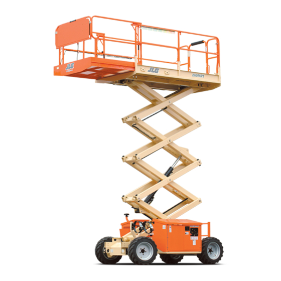
JLG 260MRT Operation And Safety Manual
Hide thumbs
Also See for 260MRT:
- Service and maintenance manual (107 pages) ,
- Operation and safety manual (93 pages) ,
- Quick start manual (9 pages)

Subscribe to Our Youtube Channel
Related Manuals for JLG 260MRT


Summary of Contents for JLG 260MRT
- Page 1 Operation and Safety Manual Original Instructions - Keep this manual with the machine at all times. Model 260MRT SN 0200000100 - 0200269760 ANSI AS/NZS 3121219 December 11, 2019 - Rev J ®...
- Page 2 WARNING Operating, servicing and maintaining this vehicle or equipment can expose you to chemicals including engine exhaust, carbon monoxide, phthalates, and lead, which are known to the State of California to cause cancer and birth defects or other reproductive harm. To minimize exposure, avoid breathing exhaust, do not idle the engine except as necessary, service your vehicle or equipment in a well-ventilated area and wear gloves or wash your hands frequently when servicing.
- Page 3 The purpose of this manual is to provide owners, users, operators, lessors, and lessees with the precautions and operating procedures essential for the safe and proper machine operation for its intended purpose. Due to continuous product improvements, JLG Industries, Inc. reserves the right to make specification changes without prior notification. Contact JLG Industries, Inc. for updated information.
- Page 4 FOREWORD SAFETY ALERT SYMBOLS AND SAFETY SIGNAL WORDS This is the Safety Alert Symbol. It is used to alert you to the potential personal injury hazards. Obey all safety messages that follow this symbol to avoid possible injury or death INDICATES A POTENTIALLY HAZARDOUS SITUATION.
- Page 5 Modifications Product Safety JLG INDUSTRIES, INC. SENDS SAFETY RELATED BULLETINS TO THE OWNER OF RECORD OF THIS MACHINE. CONTACT JLG INDUSTRIES, INC. TO ENSURE THAT THE Contact: CURRENT OWNER RECORDS ARE UPDATED AND ACCURATE. Product Safety and Reliability Department JLG Industries, Inc.
- Page 6 FOREWORD REVISION LOG Original Issue A - June 27, 2005 Revised B - July 17, 2006 Revised C - March 29, 2007 Revised D - October 22, 2008 Revised E - April 15, 2010 Revised F - May 14, 2010 Revised G - June 5, 2012 Revised...
-
Page 7: Table Of Contents
TABLE OF CONTENTS SECTION - 1 - SAFETY PRECAUTIONS Function Check........2-5 DUAL FUEL SYSTEM (IF EQUIPPED) . - Page 8 TABLE OF CONTENTS SECTION - 6 - ACCESSORIES Auto Leveling ........4-3 Manual Level Adjustment (Trim) .
- Page 9 TABLE OF CONTENTS SECTION - 8 - INSPECTION AND REPAIR LOG LIST OF TABLES Beaufort Scale (For Reference Only) ......1-3 LIST OF FIGURES Minimum Approach Distances (M.A.D.) .
- Page 10 TABLE OF CONTENTS 3121219...
-
Page 11: Section 1 - Safety Precautions
These sections contain the responsibilities of the owner, user, operator, lessor, and lessee concerning safety, training, inspec- tion, maintenance, application, and operation.If there are any questions with regard to safety, training, inspection, mainte- nance, application, and operation, please contact JLG Industries, Inc. (“JLG”). 3121219... -
Page 12: Workplace Inspection
JLG. unit. • Before operation, check work area for overhead hazards such •... - Page 13 SECTION 1 - SAFETY PRECAUTIONS DO NOT OPERATE THE MACHINE WHEN WIND CONDITIONS EXCEED 28 MPH (12.5 M/S). Table 1-1. Beaufort Scale (For Reference Only) Wind Speed Beaufort Description Land Conditions Number 0-0.2 Calm Calm. Smoke rises vertically 0.3-1.5 Light air Wind motion visible in smoke 1.6-3.3 Light breeze...
-
Page 14: Machine Indspection
• Check the machine for modifications to original components. end of travel. This applies both to machines in operation or in Ensure that any modifications have been approved by JLG. the stowed position. • Avoid accumulation of debris on platform deck. Keep mud, oil, •... -
Page 15: Trip And Fall Hazards
• When two or more persons are in the platform, the operator shall be responsible for all machine operations. • JLG Industries, Inc. recommends that all persons in the plat- • Always ensure that power tools are properly stowed and never form wear a full body harness with a lanyard attached to an left hanging by their cord from the platform work area. -
Page 16: Electrocution Hazards
SECTION 1 - SAFETY PRECAUTIONS Electrocution Hazards • This machine is not insulated and does not provide protection from contact or proximity to electrical current. • Keep both feet firmly positioned on the platform floor at all times. Never position ladders, boxes, steps, planks, or similar items on unit to provide additional reach for any purpose. -
Page 17: Minimum Approach Distances (M.a.d.)
SECTION 1 - SAFETY PRECAUTIONS • Maintain safe clearance from electrical lines, apparatus, or any • The minimum approach distance may be reduced if insulating barriers are installed to prevent contact, and the barriers are energized (exposed or insulated) parts in accordance with the Minimum Approach Distance (MAD) as specified in Table 1-1. -
Page 18: Tipping Hazards
Do not exceed the allowable sideslope and grade platform. Keep all loads within the confines of the platform, while driving unless authorized by JLG. • Keep the chassis of the machine a minimum of 2 ft (0.6 m) from holes, bumps, drop-offs, obstructions, debris, concealed holes, and other potential hazards at the ground level. -
Page 19: Crushing And Collision Hazards
SECTION 1 - SAFETY PRECAUTIONS • If scissor arm assembly or platform is caught so that one or • Always post a lookout when driving in areas where vision is more wheels are off the ground, all persons must be removed obstructed. -
Page 20: Towing, Lifting, And Hauling
SECTION 1 - SAFETY PRECAUTIONS TOWING, LIFTING, AND HAULING MAINTENANCE • Never allow personnel in platform while towing, lifting, or General hauling. This section contains general safety precautions which must be • This machine should not be towed, except in the event of observed during maintenance of this machine. -
Page 21: Battery Hazards
SECTION 1 - SAFETY PRECAUTIONS Battery Hazards • Always disconnect batteries when servicing electrical compo- nents or when performing welding on the machine. • Always disconnect batteries when servicing electrical compo- • Shut down the engine (if equipped) while fuel tanks are being nents or when performing welding on the machine. - Page 22 SECTION 1 - SAFETY PRECAUTIONS NOTES: 1-12 3121219...
-
Page 23: Section 2 - User Responsibilities, Machine Preparation, And Inspection
SECTION 2 - USER RESPONSIBILITIES, MACHINE PREPARATION, AND INSPECTION SECTION 2. USER RESPONSIBILITIES, MACHINE PREPARATION, AND INSPECTION PERSONNEL TRAINING The safest means to operate the machine where overhead obstructions, other moving equipment, and obstacles, The aerial platform is a personnel handling device; so it is neces- depressions, holes, drop-offs. -
Page 24: 2.2 Preparation, Inspection, And Maintenance
SECTION 2 - USER RESPONSIBILITIES, MACHINE PREPARATION, AND INSPECTION 2.2 PREPARATION, INSPECTION, AND MAINTENANCE JLG INDUSTRIES, INC. RECOGNIZES A FACTORY-TRAINED SERVICE TECHNICIAN AS A The following table covers the periodic machine inspections and PERSON WHO HAS SUCCESSFULLY COMPLETED THE JLG SERVICE TRAINING SCHOOL maintenance recommended by JLG Industries, Inc. -
Page 25: Inspection And Maintenance Table
Preventative Maintenance At intervals as specified in the Service and Maintenance Owner, Dealer, or User Qualified JLG Mechanic Service and Maintenance Manual Manual. NOTE: Inspection forms are available from JLG. Use the Service and Maintenance Manual to perform inspections. 3121219... -
Page 26: Pre-Start Inspection
SECTION 2 - USER RESPONSIBILITIES, MACHINE PREPARATION, AND INSPECTION PRE-START INSPECTION Operation and Safety Manuals – Make sure a copy of the Operation and Safety Manual is enclosed in the weather The Pre-Start Inspection should include each of the following: resistant storage container. -
Page 27: Preparing The Machine For Operation
SECTION 2 - USER RESPONSIBILITIES, MACHINE PREPARATION, AND INSPECTION Preparing the Machine for Operation Function Check Emergency Ground Control Station Perform the Function Check as follows: Turn key-switch to ground control select. From the ground emergency control panel with no load in the platform: Pull emergency stop switch to the On position. - Page 28 SECTION 2 - USER RESPONSIBILITIES, MACHINE PREPARATION, AND INSPECTION From the platform control console: With the platform in the stowed position: a. Ensure that the control console is firmly secured in the a. Drive the machine on a level grade and stop proper location.
-
Page 29: Dual Fuel System (If Equipped)
SECTION 2 - USER RESPONSIBILITIES, MACHINE PREPARATION, AND INSPECTION DUAL FUEL SYSTEM (IF EQUIPPED) Changing from LP Gas to Gasoline. With the engine operating on LP gas under a no load condi- tion, position the LPG/GAS SELECT switch at the platform control station to the GAS SELECT position. -
Page 30: Walk Around Inspection Diagram
SECTION 2 - USER RESPONSIBILITIES, MACHINE PREPARATION, AND INSPECTION 12,13 21 NOT SHOWN 12,13 Figure 2-1. Walk Around Inspection Diagram 3121219... -
Page 31: General
SECTION 2 - USER RESPONSIBILITIES, MACHINE PREPARATION, AND INSPECTION GENERAL Begin the “Walk-Around Inspection” at Item 1, as noted on the DO NOT OVERLOOK VISUAL INSPECTION OF CHASSIS UNDERSIDE. CHECKING THIS diagram.Continue to the right (counterclockwise viewed from AREA OFTEN RESULTS IN DISCOVERY OF CONDITIONS WHICH COULD CAUSE EXTEN- top) checking each item in sequence for the conditions listed in SIVE MACHINE DAMAGE. - Page 32 SECTION 2 - USER RESPONSIBILITIES, MACHINE PREPARATION, AND INSPECTION Fuel Tank (Gasoline or Diesel Engine) - Filler cap secure, Hydraulic Pump - Pump properly secured, no visible dam- sight gauge visible, no damage or leaks. age, no evidence of leakage. Hoses and fittings properly secured, no visible damage, no evidence of leaks.
-
Page 33: Section 3 - User Responsibilities And Machine Control
SECTION 3 - USER RESPONSIBILITIES AND MACHINE CONTROL SECTION 3. USER RESPONSIBILITIES AND MACHINE CONTROL GENERAL OPERATING CHARACTERISTICS AND LIMITATIONS General A thorough knowledge of the operating characteristics and lim- itations of the machine is always the first requirement for any THE MANUFACTURER HAS NO DIRECT CONTROL OVER MACHINE APPLICATION AND user, regardless of user’s experience with similar types of equip- OPERATION, CONFORMANCE WITH GOOD SAFETY PRACTICES IN THESE AREAS IS THE... -
Page 34: Controls And Indicators
SECTION 3 - USER RESPONSIBILITIES AND MACHINE CONTROL CONTROLS AND INDICATORS ground controls and the key can be removed to disable the machine. (Refer to Figure 3-1.) NOTE: With the Power Selector switch in the off position, the key can be The machine is equipped with control panels that use symbols removed in order to incapacitate the machine on the jobsite to instead of words to indicate control functions. - Page 35 SECTION 3 - USER RESPONSIBILITIES AND MACHINE CONTROL Water Temperature LED - Illuminates when engine water Ignition/Emergency Stop Switch - A two-position, red, mushroom-shaped ignition/emergency stop switch, when temperature becomes overheated. positioned to ON with the power selector switch positioned Charge Pressure - Illuminates when the charge pressure to ground, furnishes operating power to the ground control drops below 70 psi (4.8 bar), indicating the charge filter is...
-
Page 36: Ground - Control Station
SECTION 3 - USER RESPONSIBILITIES AND MACHINE CONTROL 14. Platform/Ground Select Switch 15. Latch 16. Circuit Breaker 17. Alternator LED 18. Oil Pressure LED 19. Glow Plug Switch 20. Water Temperature LED 21. Hydraulic Charge Pressure LED 22. Lift Switch 1 705 729 B 23. -
Page 37: Platform Control Station
SECTION 3 - USER RESPONSIBILITIES AND MACHINE CONTROL PLATFORM CONTROL STATION (Refer to Figure 3-2.) DO NOT USE HIGH ENGINE SPEED WHEN DRIVING IN CLOSE QUARTERS OR WHEN DRIVING IN REVERSE. Start Switch - A momentary contact, push button type switch that supplies electrical power to the starter solenoid NOTE: If machine is being operated in high range speed and the plat-... - Page 38 SECTION 3 - USER RESPONSIBILITIES AND MACHINE CONTROL Drive Select Switch - The drive switch provides for driving Glow Plug Switch - Glow Plug Switch - A momentary con- tact, push button type switch that supplies electrical power the lift. Drive is activated by selecting the drive switch and positioning the joystick forward or backward.
-
Page 39: Platform - Control Station
SECTION 3 - USER RESPONSIBILITIES AND MACHINE CONTROL 1. Start Switch 2. Joystick 3. Steer Switch 4. Speed/Generator Switch 1706763 A 5. Emergency Stop Switch 6. Lift Switch 7. Drive Switch 8. Horn 9. Enable Trigger 10. Glow Plug Switch 11. -
Page 40: Platform Control Front Panel
SECTION 3 - USER RESPONSIBILITIES AND MACHINE CONTROL Platform Control Front Panel the right, activate the switch on top of the controller to the right. The leveling jack indicator light for the side (Refer to Figure 3-3.) selected will be lit. Fuel/Glow Plug Selector Switch - Selects which fuel source will be used. -
Page 41: Platform - Control Front Panel
SECTION 3 - USER RESPONSIBILITIES AND MACHINE CONTROL 1. Dual Fuel Selector Switch 2. Diesel Fuel Selector Switch 3. Outrigger Switch Figure 3-3. Platform - Control Front Panel 3121219... -
Page 42: Indicator Panel Led's
SECTION 3 - USER RESPONSIBILITIES AND MACHINE CONTROL Indicator Panel LED’s (Refer to Figure 3-4.) FOR MACHINES EQUIPPED WITH THE YANMAR DIESEL ENGINE, THE TIMER RELAY Drive - This LED will illuminate when the drive select button MUST SEAT THE FUEL SOLENOID WITH ITS INITIAL PULSE, OR THE ENGINE WILL NOT is activated. -
Page 43: Platform - Indicator Panel
SECTION 3 - USER RESPONSIBILITIES AND MACHINE CONTROL Drive Lift Fuel Gauge Tilt Engine Distress Leveling Jacks (Retracted) Leveling Jacks (Set) 32 52 6 95 B Figure 3-4. Platform - Indicator Panel 3121219 3-11... -
Page 44: Decals
SECTION 3 - USER RESPONSIBILITIES AND MACHINE CONTROL DECALS ANSI, ANSI Export, CSA OAD01870 3-12 3121219... - Page 45 SECTION 3 - USER RESPONSIBILITIES AND MACHINE CONTROL 12 35 OAD01880 3121219 3-13...
- Page 46 SECTION 3 - USER RESPONSIBILITIES AND MACHINE CONTROL ANSI SPA, POR ENG, SPA ENG, FRE Item (0259792-N) (0259795-K) (0259794-K) (0272257-H) 1 - 6 1703816 1704699 1704691 1704684 1704138 1704138 1704138 1704138 1704529 1704529 1704529 1704529 1701509 1701509 1701509 1701509 1703811 1703811 1703811 1703811...
- Page 47 SECTION 3 - USER RESPONSIBILITIES AND MACHINE CONTROL ANSI SPA, POR ENG, SPA ENG, FRE Item (0259792-N) (0259795-K) (0259794-K) (0272257-H) 31 - 32 1705303 1705303 1001223055 1001224052 1001224049 1001223971 36 - 39 1001223453 1001223453 1001231801 3121219 3-15...
-
Page 48: Ce, Aus
SECTION 3 - USER RESPONSIBILITIES AND MACHINE CONTROL CE, AUS OAD01890 3-16 3121219... - Page 49 SECTION 3 - USER RESPONSIBILITIES AND MACHINE CONTROL OAD01900 3121219 3-17...
- Page 50 SECTION 3 - USER RESPONSIBILITIES AND MACHINE CONTROL CE, AUS Item (0275087-G) CE, AUS Item 27 - 29 (0275087-G) 1704412 1 - 6 31 - 34 1704548 1702788 1704138 1701542 (Dual Fuel) 1704529 1701505 (Diesel) 1704559 1701509 1702773 1703811 1701435 1703812 1703814 1704277...
-
Page 51: Section 4 - Machine Operation
SECTION 4 - MACHINE OPERATION SECTION 4. MACHINE OPERATION DESCRIPTION ENGINE OPERATION This machine is a self-propelled hydraulic lift equipped with a Power Selector Switch work platform on an elevating scissor mechanism. Vibrations emitted by these machines are not hazardous to an operator in The power selector switch functions to direct electrical power to the work platform. -
Page 52: Starting Procedure
SECTION 4 - MACHINE OPERATION Starting Procedure IF STARTING MACHINE FROM THE PLATFORM CONTROL STATION, PLACE THE ENGINE SPEED CONTROL TO THE LOW POSITION PRIOR TO STARTING THE ENGINE. NOTE: Initial starting should always be performed from the Ground If starting the machine from the ground controls, position Control Station. -
Page 53: Operating Characteristics
SECTION 4 - MACHINE OPERATION OPERATING CHARACTERISTICS Continue to engage the leveling jacks until the tilt light stops blinking and is no longer lit. Leveling Jacks NOTE: If you receive a 2/5 flash code through the system fault light at the platform control station the machine is unable to level. -
Page 54: Platform
SECTION 4 - MACHINE OPERATION PLATFORM NOTE: There is an override feature on the Leveling Jack system that allows the operator to adjust (trim) the level of the machine to the left or right when the platform is completely lowered. Use the Platform Loading following instructions to adjust the level of the machine. -
Page 55: Raising
SECTION 4 - MACHINE OPERATION Raising Lowering DO NOT RAISE PLATFORM EXCEPT ON A SMOOTH, FIRM, AND LEVEL SURFACE, FREE OF ENSURE SCISSOR ARM AREA IS FREE OF PERSONNEL PRIOR TO LOWERING PLATFORM. OBSTRUCTIONS AND HOLES. ENSURE PLATFORM EXTENSION IS COMPLETELY RETRACTED PRIOR TO LOWERING PLATFORM. -
Page 56: Platform Extension
SECTION 4 - MACHINE OPERATION Platform Extension DRIVING The machine is equipped with a mechanical extension deck, which adds 3 ft (0.9 m) to the front of the platform, giving the DO NOT DRIVE WITH PLATFORM RAISED EXCEPT ON A SMOOTH, FIRM AND LEVEL operator better access to work-sites. -
Page 57: Driving Forward
SECTION 4 - MACHINE OPERATION Driving Forward Driving in Reverse Place the power selector switch at the ground control sta- Position the power selector switch at the ground control sta- tion to platform. tion to platform. Position the emergency stop switch at the platform control Position the emergency stop switch at the platform control station to the on position. -
Page 58: Grade And Sideslope Depiction
SECTION 4 - MACHINE OPERATION LE V E L Figure 4-1. Grade and Sideslope Depiction 3121219... -
Page 59: Parking And Stowing
Chock at least two wheels when parking the machine for an extended period of time. NOTE: If lifting becomes necessary from the lifting lugs, Jlg Industries Inc. recommends the use of a proper spreader bar to avoid dam- Turn the power selector switch to off and remove the key to age to the machine. -
Page 60: Towing
SECTION 4 - MACHINE OPERATION TOWING After moving the machine, complete the following procedures: Position the machine on a firm, level surface. Although towing the machine is prohibited, provisions for mov- ing the machine, in case of a malfunction or power failure, have Chock the wheels securely. -
Page 61: Lifting Chart
SECTION 4 - MACHINE OPERATION WHEELBASE MODEL (in) (in) (in) 260MRT 41.5 28.5 Figure 4-2. Lifting Chart 3121219 4-11... -
Page 62: Platform Rails - Fold-Down Procedure
SECTION 4 - MACHINE OPERATION PLATFORM RAILS - FOLD-DOWN PROCEDURE To fold down each of the rails, remove the bail pins for that rail. Taking a firm hold on the top rail, carefully lower until the top rail is fully folded in the down position. DO NOT RAISE PLATFORM WITH RAILS FOLDED DOWN. -
Page 63: Platform Rails - Fold Down Sequence - Front/Rear
SECTION 4 - MACHINE OPERATION Figure 4-3. Platform Rails - Fold Down Sequence - Front/Rear Rails 3121219 4-13... -
Page 64: Platform Rails - Fold Down Sequence - Deck Extension Side
SECTION 4 - MACHINE OPERATION Figure 4-4. Platform Rails - Fold Down Sequence - Deck Extension Side Rails 4-14 3121219... -
Page 65: Platform Rails - Fold Down Sequence - Main Platform Side
SECTION 4 - MACHINE OPERATION Figure 4-5. Platform Rails - Fold Down Sequence - Main Platform Side Rails 3121219 4-15... - Page 66 SECTION 4 - MACHINE OPERATION 4-16 3121219...
-
Page 67: Section 5 - Emergency Procedures
SECTION 5 - EMERGENCY PROCEDURES SECTION 5. EMERGENCY PROCEDURES GENERAL select switch in the ground position and operate the lift switch to lift up or down. This section provides information on the procedures to be fol- Manual Descent lowed and on the systems and controls to be used in the event an emergency situation is encountered during machine operation. -
Page 68: Operator Unable To Control Machine
SECTION 5 - EMERGENCY PROCEDURES Operator Unable to Control Machine Platform Caught Overhead If the platform becomes jammed or snagged in overhead struc- Operate the machine from ground controls ONLY with the tures or equipment, do the following: assistance of other personnel and equipment (cranes, over- head hoists, etc.) as may be required to safely remove the Shut off the machine. -
Page 69: Righting Of Tipped Machine
JLG Industries, Inc. must be notified immediately of any incident A forktruck of suitable capacity or equivalent equipment should involving a JLG product. Even if no injury or property damage is be placed under the elevated side of the chassis, with a crane or... - Page 70 SECTION 5 - EMERGENCY PROCEDURES 3121219...
-
Page 71: Section 6 - Accessories
SECTION 6 - ACCESSORIES SECTION 6. ACCESSORIES Table 6-1. Available Accessories Market Accessory ANSI ANSI (USA Only) 1/2 Airline Platform Worklights Platform Rail Padding 3121219... -
Page 72: 1/2 Airline
SECTION 6 - ACCESSORIES 1/2 AIRLINE PLATFORM WORKLIGHTS The 1/2 Airline is a fitting for air-powered tools that is mounted in the platform. The Platform Worklights accessory consists of two 12V lights mounted to the platform railings. 3121219... -
Page 73: Platform Rail Padding
SECTION 6 - ACCESSORIES PLATFORM RAIL PADDING With Deck Bumpers OAD00050 1. Deck Bumpers Platform Rail Padding provides bumpers to the top plat- form rails in order to prevent damage to the platform itself This accessory is also available with proximity switches, as well as objects it may come into contact with during which attaches a padded frame to the bottom of the plat- operation. - Page 74 SECTION 6 - ACCESSORIES NOTES: 3121219...
-
Page 75: Section - 7 - General Specifications And Operator Mainte
SECTION 7 - GENERAL SPECIFICATIONS AND OPERATOR MAINTENANCE SECTION 7. GENERAL SPECIFICATIONS AND OPERATOR MAINTENANCE INTRODUCTION Other Publications Available Specific to this Machine: Service and Maintenance Manual (ANSI) ......3121108 This section of the manual provides additional necessary infor- Illustrated Parts Manual (ANSI)..........3121109 mation to the operator for proper operation and maintenance of this machine. -
Page 76: Operating Specifications
SECTION 7 - GENERAL SPECIFICATIONS AND OPERATOR MAINTENANCE OPERATING SPECIFICATIONS Table 7-1. Operating Specifications Gross Machine Weight (Approximate) 7,330 lb Table 7-1. Operating Specifications (3,325 kg) Maximum Drive Speed 3.5 mph Maximum Occupants (5.6 kmh) Maximum Workload (Capacity) 1,250 lb (570 kg) Drive Speed (slow) - sec./25ft (7.6 m) 7-11 Extension Only:... -
Page 77: Dimensional Data
SECTION 7 - GENERAL SPECIFICATIONS AND OPERATOR MAINTENANCE Dimensional Data Table 7-3. Capacities Table 7-2. Dimensional Data Engine Crankcase Gasoline 3.4 qt (3.25 L) Overall Height Stowed (rails up) Diesel 4.2 qt (4 L) Global: 7.75 ft (2.4 m) Coolant Sp. -
Page 78: Engine
Fuel Type Gasoline/LP Gas Gasoline/ LP Gas Diesel Diesel (1) - JLG machines equipped with TIER 3 carbureted model engine: • Excessive exhaust temperature: This may rapidly or immediately Kubota DF752-E2 damage the catalyst (if equipped). Engine overheating may also occur. - Page 79 SECTION 7 - GENERAL SPECIFICATIONS AND OPERATOR MAINTENANCE Kubota Dual Fuel (WG752-GL-G3) Kubota Diesel (D1005-E4B) Emissions CARB, EPA Phase 3 Emissions CARB, EPA Tier 4 Final, and EU Stage V Gasoline - 87 Octane minium Diesel: - Ethanol/Gas Mix-10% maximum - Low Sulfur (<500 ppm) Fuel Type - Methanol/Gas Mix-5% maximum...
-
Page 80: Lubrication
When temperatures remain below -7° C (20° F), JLG Industries recommends the use of Mobil DTE13. Aside from JLG recommendations, it is not advisable to mix oils of different brands or types, as they may not contain the same required additives or be of comparable viscosities. If use of... -
Page 81: Engine Operating Temperature Specifications (Kubota)
SECTION 7 - GENERAL SPECIFICATIONS AND OPERATOR MAINTENANCE 4150548_E DIESEL Figure 7-1. Engine Operating Temperature Specifications (Kubota)- Sheet 1 of 2 3121219... -
Page 82: Engine Operating Temperature Specifications (Kubota)
SECTION 7 - GENERAL SPECIFICATIONS AND OPERATOR MAINTENANCE 4150548_E Figure 7-2. Engine Operating Temperature Specifications (Kubota)- Sheet 2 of 2 3121219... -
Page 83: Operator Maintenance
SECTION 7 - GENERAL SPECIFICATIONS AND OPERATOR MAINTENANCE OPERATOR MAINTENANCE Safety Prop TO AVOID PERSONAL INJURY, THE SAFETY PROP MUST BE USED WHENEVER MAINTE- NANCE PERFORMED ON THE MACHINE REQUIRES THE SCISSOR ARMS TO BE RAISED. To engage the safety prop, with no load in the platform, raise the platform, then rotate the prop clockwise until it hangs vertically. -
Page 84: Inspection Check Points
SECTION 7 - GENERAL SPECIFICATIONS AND OPERATOR MAINTENANCE Inspection Check Points 1 A N D 2 O N O P P O S IT E S ID E Figure 7-3. Lubrication Diagram 7-10 3121219... -
Page 85: Hydraulic Oil
SECTION 7 - GENERAL SPECIFICATIONS AND OPERATOR MAINTENANCE NOTE: Be sure to lubricate like items on each side a. Engine Oil Check/Fill Capacity - See Engine Manual NOTE: Recommended lubricating intervals are based on machine oper- Lube - See Engine Manual ations under normal conditions. -
Page 86: Tires And Wheels
JLG product from istics: service immediately. Arrangements must be made for replacement of the tire or tire assembly. -
Page 87: Wheel Replacement
SECTION 7 - GENERAL SPECIFICATIONS AND OPERATOR MAINTENANCE Wheel Replacement Start all nuts by hand to prevent cross threading. DO NOT use a lubricant on threads or nuts. The rims installed on each product model have been designed Tighten nuts in the following sequence: for stability requirements which consist of track width, tire pres- sure, and load capacity. -
Page 88: Supplemental Information
SECTION 7 - GENERAL SPECIFICATIONS AND OPERATOR MAINTENANCE SUPPLEMENTAL INFORMATION TORQUE SEQUENCE 1st Stage 2nd Stage 3rd Stage The following information is provided in accordance with the 35 - 55 ft lbs 65 - 80 ft lbs 90 - 105 ft lbs requirements of the European Machinery Directive 2006/42/EC (49 - 77 Nm) (91 - 112 Nm) -
Page 89: Section 8 - Inspection And Repair Log
SECTION 8 - INSPECTION AND REPAIR LOG SECTION 8. INSPECTION AND REPAIR LOG Table 8-1. Inspection and Repair Log Date Comments 3121219... - Page 90 SECTION 8 - INSPECTION AND REPAIR LOG Table 8-1. Inspection and Repair Log Date Comments 3121219...
- Page 92 Corporate Office JLG Industries, Inc. 1 JLG Drive McConnellsburg, PA 17233-9533 USA (717) 485-5161 (Corporate) (877) 554-5438 (Customer Support) (717) 485-6417 Visit our website for JLG Worldwide Locations. www.jlg.com...
Need help?
Do you have a question about the 260MRT and is the answer not in the manual?
Questions and answers