Huawei UPS5000-E Series User Manual
25 kva power modules
Hide thumbs
Also See for UPS5000-E Series:
- User manual (300 pages) ,
- Quick manual (20 pages) ,
- User manual (203 pages)

Related Manuals for Huawei UPS5000-E Series


Summary of Contents for Huawei UPS5000-E Series
- Page 1 UPS5000-E-(25 kVA-125 kVA) User Manual (25 kVA power modules) Issue Date 2020-01-10 HUAWEI TECHNOLOGIES CO., LTD.
- Page 2 Notice The purchased products, services and features are stipulated by the contract made between Huawei and the customer. All or part of the products, services and features described in this document may not be within the purchase scope or the usage scope. Unless otherwise specified in the contract, all statements, information, and recommendations in this document are provided "AS IS"...
-
Page 3: About This Document
Indicates a potentially hazardous situation which, if not avoided, could result in equipment damage, data loss, performance deterioration, or unanticipated results. NOTICE is used to address practices not related to personal injury. Issue 06 (2020-01-10) Copyright © Huawei Technologies Co., Ltd. - Page 4 Updated the maximum voltage and current which the monitoring interface card can support, optimized the dual bus scenario, and updated the routine maintenance. Issue 02 (2015-08-20) Deleted V100R001 from the version information. Issue 01 (2015-04-02) This issue is the first official release. Issue 06 (2020-01-10) Copyright © Huawei Technologies Co., Ltd.
-
Page 5: Table Of Contents
2.4.2.3 Dry Contact Card ............................25 2.4.2.4 (Optional) Backfeed Protection Card .......................27 2.4.2.5 (Optional) Dry Contact Extended Card ......................27 2.4.2.6 Monitoring Interface Card ..........................28 2.5 Typical configurations ............................32 2.5.1 Single UPS ................................33 Issue 06 (2020-01-10) Copyright © Huawei Technologies Co., Ltd. - Page 6 3.2.13.6 (Optional) Connecting the Backfeed Protection Card ..................73 3.2.13.7 Connecting Communications Cables ......................74 3.3 Installation Verification ............................75 4 User Interface .......................... 77 4.1 LCD Interface ..............................77 4.1.1 LCD ..................................77 4.1.2 LCD Menu ................................78 Issue 06 (2020-01-10) Copyright © Huawei Technologies Co., Ltd.
- Page 7 5.6.4.2 Download over the WebUI ..........................151 5.7 Transferring to Maintenance Bypass Mode ......................152 5.8 Transferring from Maintenance Bypass Mode to Normal Mode ................154 5.9 Performing EPO ..............................155 Issue 06 (2020-01-10) Copyright © Huawei Technologies Co., Ltd.
- Page 8 8.8 System Electrical Specifications ......................... 185 A Menu Hierarchy ........................186 A.1 Menus on the LCD ............................186 A.2 Menus on the WebUI ............................188 B Alarm List ..........................203 C Acronyms and Abbreviations .................... 213 Issue 06 (2020-01-10) Copyright © Huawei Technologies Co., Ltd.
-
Page 9: Safety Information
The "NOTICE", "CAUTION", "WARNING", and "DANGER" statements in this document do not cover all the safety instructions. They are only supplements to the safety instructions. Huawei will not be liable for any consequence caused by the violation of general safety requirements or design, production, and usage safety standards. - Page 10 Keep irrelevant people away from the equipment. Only operators are allowed to access the equipment. Use insulated tools or tools with insulated handles, as shown in the following figure. Issue 06 (2020-01-10) Copyright © Huawei Technologies Co., Ltd.
- Page 11 To avoid electric shock, do not connect safety extra-low voltage (SELV) circuits to telecommunication network voltage (TNV) circuits. Issue 06 (2020-01-10) Copyright © Huawei Technologies Co., Ltd.
-
Page 12: Personnel Requirements
Do not power on the equipment before it is installed or confirmed by professionals. 1.2 Personnel Requirements Personnel who plan to install or maintain Huawei equipment must receive thorough training, understand all necessary safety precautions, and be able to correctly perform all operations. - Page 13 When selecting, connecting, and routing cables, follow local safety regulations and rules. The static electricity generated by human bodies may damage the electrostatic-sensitive components on boards, for example, the large-scale integrated (LSI) circuits. Issue 06 (2020-01-10) Copyright © Huawei Technologies Co., Ltd.
-
Page 14: Installation Environment Requirements
Ensure that the equipment room provides good heat insulation, and the walls and floor are dampproof. Install a rat guard at the door of the equipment room. Issue 06 (2020-01-10) Copyright © Huawei Technologies Co., Ltd. -
Page 15: Mechanical Safety
Before hoisting objects, ensure that hoisting tools are firmly secured onto a load-bearing object or wall. Ensure that the angle formed by two hoisting cables is no more than 90 degrees, as shown in the following figure. Issue 06 (2020-01-10) Copyright © Huawei Technologies Co., Ltd. - Page 16 Do not climb higher than the fourth rung of the ladder from the top. Ensure that your body's center of gravity does not shift outside the legs of the ladder. Issue 06 (2020-01-10) Copyright © Huawei Technologies Co., Ltd.
- Page 17 Metal shavings from drilling may short-circuit boards inside the equipment. Obtain the consent from the customer, subcontractor, and Huawei before drilling. Wear goggles and protective gloves when drilling holes. ...
-
Page 18: Device Running Safety
A UPS can be used to serve resistive-capacitive loads, resistive loads, and micro-inductive loads. It is recommended that a UPS not be used for pure capacitive loads, pure inductive loads, and half-wave rectification loads. A UPS does not apply to regeneration loads. Issue 06 (2020-01-10) Copyright © Huawei Technologies Co., Ltd. -
Page 19: Battery Safety
Use dedicated insulated tools. Move batteries in the required direction. Do not place a battery upside down or tilt it. Issue 06 (2020-01-10) Copyright © Huawei Technologies Co., Ltd. - Page 20 The site must be equipped with qualified fire extinguishing facilities, such as firefighting sands and powder fire extinguishers. To ensure battery safety and battery management accuracy, use batteries provided with the UPS by Huawei. Huawei is not responsible for any battery faults caused by batteries not provided by Huawei. Battery Installation Before installing batteries, observe the following safety precautions: ...
- Page 21 Do not charge a battery when the ambient temperature is below the lower limit of the operating temperature (charging is forbidden at 0° C). Low-temperature charging may cause crystallization, which will result in a short circuit inside the battery. Issue 06 (2020-01-10) Copyright © Huawei Technologies Co., Ltd.
-
Page 22: Others
UPS output voltage level or frequency. Doing so may affect the power supply to equipment. Exercise caution when setting battery parameters. Incorrect settings will affect the power supply and battery lifespan. Issue 06 (2020-01-10) Copyright © Huawei Technologies Co., Ltd. -
Page 23: Overview
UPS model number. Figure 2-1 UPS model number Table 2-1 Model number details Item Description Product category UPS family 5000 UPS subcategory Output capacity 125K: 125 kVA Rack type F125: 125 kVA rack Issue 06 (2020-01-10) Copyright © Huawei Technologies Co., Ltd. -
Page 24: Benefits
If a surge protection box is configured, the UPS5000-E can provide the 5 kA surge protection capability. If a surge protection box (20 kA) is configured, the UPS5000-E can provide level C surge protection. Issue 06 (2020-01-10) Copyright © Huawei Technologies Co., Ltd. -
Page 25: Working Principle
DC power into high-precision AC outputs. The conversions protect loads from interference such as input harmonics, glitches, and voltage transients. Figure 2-3 shows a conceptual diagram of the UPS working in normal mode. Issue 06 (2020-01-10) Copyright © Huawei Technologies Co., Ltd. -
Page 26: Bypass Mode
UPS which means it may be affected by mains outage, and incorrect AC voltage or frequency. Figure 2-4 shows a conceptual diagram of the UPS working in bypass mode. Issue 06 (2020-01-10) Copyright © Huawei Technologies Co., Ltd. -
Page 27: Battery Mode
If the mains input is abnormal or the rectifier becomes abnormal, the UPS transfers to battery mode. The power module obtains DC power from batteries, and the power is converted into AC output by the inverter. Issue 06 (2020-01-10) Copyright © Huawei Technologies Co., Ltd. -
Page 28: Maintenance Bypass Mode
2.3.2.4 Maintenance Bypass Mode When the UPS works in maintenance bypass mode, the current flows through the maintenance bypass instead of the power module. You can maintain the circuit inside the cabinet. Issue 06 (2020-01-10) Copyright © Huawei Technologies Co., Ltd. -
Page 29: Eco Mode
ECO voltage range, the UPS transfers from bypass mode to normal mode. In bypass mode or normal mode, the rectifier keeps working and charges batteries using a charger. The ECO mode delivers a high efficiency. Issue 06 (2020-01-10) Copyright © Huawei Technologies Co., Ltd. -
Page 30: Overview
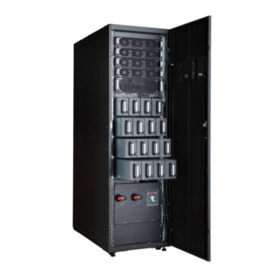
Manual startup is required to ensure that the inverter is in standby state and the power flow has reached the inverter. 2.4 Overview 2.4.1 Structure Figure 2-8 shows the front view of the UPS5000-E with the door open. Issue 06 (2020-01-10) Copyright © Huawei Technologies Co., Ltd. -
Page 31: Control Module
A backfeed protection card or dry contact extended card can be inserted into this subrack. Figure 2-9 shows the signal panel on the control module. Issue 06 (2020-01-10) Copyright © Huawei Technologies Co., Ltd. -
Page 32: Ecm
In a parallel system, the PARALLEL ports on ECMs are interconnected in the shape of a ring using parallel cables. A hot swappable BSC is used in a dual-bus system to process the communication information between two UPS systems. Table 2-2 describes the functions of the ECM. Issue 06 (2020-01-10) Copyright © Huawei Technologies Co., Ltd. -
Page 33: Dry Contact Card
The dry contact card allows the UPS to detect and manage the switch status of the battery system (including the external battery switch) and implement remote emergency power-off (EPO). Figure 2-11 shows control signal ports on the dry contact card. Issue 06 (2020-01-10) Copyright © Huawei Technologies Co., Ltd. - Page 34 EPO_12V +12 V EPO_12V port, EPO is triggered. EPO_NC EPO port If the normally closed Connected (NC) port is EPO_12V +12 V disconnected from the EPO_12V port, EPO Issue 06 (2020-01-10) Copyright © Huawei Technologies Co., Ltd.
-
Page 35: Optional) Backfeed Protection Card
2.4.2.5 (Optional) Dry Contact Extended Card The dry contact extended card provides five signal output ports and five signal input ports. For details, see the UPS5000 Dry Contact Extended Card User Manual (03021RKN). Issue 06 (2020-01-10) Copyright © Huawei Technologies Co., Ltd. -
Page 36: Monitoring Interface Card
Silk Screen Description DO_1 DO_1 is used to output alarms and indicates critical alarms by default. It can be set to indicate minor alarms, bypass mode, battery mode, or low battery voltage. Issue 06 (2020-01-10) Copyright © Huawei Technologies Co., Ltd. - Page 37 Signal cables must be double-insulated twisted cables. If the cable length is 25–50 m, the cross- sectional area must be 0.5–1.5 mm RS485 cables and FE cables must be shielded cables. Figure 2-13 Figure 2-14 are recommended wiring methods for DO ports. Issue 06 (2020-01-10) Copyright © Huawei Technologies Co., Ltd.
- Page 38 User Manual (25 kVA power modules) 2 Overview Figure 2-13 Wiring method 1 Figure 2-14 Wiring method 2 Figure 2-15 Table 2-6 describe the COM1 pin definitions. Figure 2-15 COM1 pins Issue 06 (2020-01-10) Copyright © Huawei Technologies Co., Ltd.
- Page 39 Table 2-6 COM1 pin definition Description RS485- RS485+ 12V_PORT Figure 2-16 Table 2-7 describe the COM2 pin definitions. Figure 2-16 COM2 pins Table 2-7 COM2 pin definition Description RS485+ RS485- RS485+ RS485- CANH0 CANL0 Issue 06 (2020-01-10) Copyright © Huawei Technologies Co., Ltd.
-
Page 40: Typical Configurations
Connect pins 1, 2, 4, and 5. Twist cables to pin 1 and pin 4 into one cable and then connect it to RS485+. Twist cables to pin 2 and pin 5 into one cable and then connect it to RS485–. 2.5 Typical configurations Table 2-9 describes typical UPS configurations. Issue 06 (2020-01-10) Copyright © Huawei Technologies Co., Ltd. -
Page 41: Single Ups
BSC is a standard configuration. Of the two UPS systems, one is a master system, and the other is a slave system. The UPS systems work in normal mode or bypass mode. Figure 2-18 shows the conceptual diagram of a dual-bus system. Issue 06 (2020-01-10) Copyright © Huawei Technologies Co., Ltd. -
Page 42: Optional Components
(derated to 630 A) input AC cabinet (PDC) transfer switch (ATS), two 3- pole 400 A mains output mold case circuit breakers (MCCBs), and two 3-pole 400 A bypass output MCCBs. Issue 06 (2020-01-10) Copyright © Huawei Technologies Co., Ltd. - Page 43 The position for installing the surge protection box subrack and ECM expansion subrack is the same, and therefore the two types of subracks cannot be used Issue 06 (2020-01-10) Copyright © Huawei Technologies Co., Ltd.
- Page 44 Ambient Ambient temperature and temperature and humidity sampling board humidity sensor applicable to batteries. BSC cable 5 m, 10 m, or 15 m Transmits bus synchronization signals in a dual-bus system. Issue 06 (2020-01-10) Copyright © Huawei Technologies Co., Ltd.
- Page 45 User Manual (25 kVA power modules) 2 Overview The ECM extended subrack does not support onsite installation. If you require this optional component, inform Huawei when you purchase the UPS. Huawei installs it before delivery. Issue 06 (2020-01-10) Copyright © Huawei Technologies Co., Ltd.
-
Page 46: Installation
Table 3-1 UPS weight Model Capacity Weight UPS5000-E-125K-F125 25 kVA 229.5 kg 50 kVA 261.5 kg 75 kVA 293.5 kg 100 kVA 325.5 kg 125 kVA 357.5 kg Figure 3-1 shows the installation dimensions. Issue 06 (2020-01-10) Copyright © Huawei Technologies Co., Ltd. -
Page 47: Installation Environment
The optimal operating temperatures for valve regulated lead acid (VRLA) batteries are 20–30° C. Operating temperatures higher than 30° C shorten the battery lifespan, and operating temperatures lower than 20° C reduce the battery backup time. Issue 06 (2020-01-10) Copyright © Huawei Technologies Co., Ltd. -
Page 48: Installation Clearances
Insulate installation tools to prevent electric shocks. Prepare the following tools and meters indicated in Table 3-2 for installation. Table 3-2 Tools and meters Tools and Meters Electric pallet truck Manual pallet truck Ladder Rubber mallet Issue 06 (2020-01-10) Copyright © Huawei Technologies Co., Ltd. - Page 49 Level instrument Polyvinyl chloride Cotton cloth Label Electrician's knife (PVC) insulation tape Electrostatic Protective gloves Insulated gloves Insulation protective discharge (ESD) shoes gloves Torque screwdriver Cable cutter Brush Flat-head screwdriver (2–5 mm) Issue 06 (2020-01-10) Copyright © Huawei Technologies Co., Ltd.
-
Page 50: Power Cables
Table 3-3 Recommended cross-sectional areas for power cables Item UPS5000-E-125K-F125 Mains input Mains input current (A) connector Recommended cross-sectional area (mm Bypass Bypass input current (A) input Recommended Issue 06 (2020-01-10) Copyright © Huawei Technologies Co., Ltd. - Page 51 Cable routing mode: For the UPS5000-E-(25 kVA–125 kVA), route cables along the wall or floor in accordance with mode C in the IEC-60364-5-52. The ambient temperature is 30° C. Issue 06 (2020-01-10) Copyright © Huawei Technologies Co., Ltd.
- Page 52 Capacity UPS5000-E- 25 kVA Mains input T1N160 TMD 125K-F125 breaker R63 FFC 3P (recommended when the short- Bypass input T1N160 TMD circuit current breaker R63 FFC 3P where the switch is Issue 06 (2020-01-10) Copyright © Huawei Technologies Co., Ltd.
-
Page 53: Unpacking And Checking
To prevent shocks or falls, move the UPS gently. After placing the UPS in the installation position, unpack it and take care to prevent scratches. Keep the UPS steady during unpacking. Issue 06 (2020-01-10) Copyright © Huawei Technologies Co., Ltd. - Page 54 Step 3 Hold the sliding plate steady. Cut and remove the binding tapes. Put down the sliding plate gently. See Figure 3-3. Figure 3-3 Removing binding tapes Step 4 Remove packing materials, as shown in Figure 3-4. Figure 3-4 Removing packing materials Issue 06 (2020-01-10) Copyright © Huawei Technologies Co., Ltd.
- Page 55 Check that the fittings comply with the packing list. If some fittings are missing or do not comply with the packing list, record the information and contact your local Huawei office immediately. Step 7 Remove the L-shaped bracket that secures the cabinet and the pallet, and secure the sliding...
-
Page 56: Installing A Single Ups
Step 2 Check whether the bottom of the cabinet is horizontal by using a level. If the cabinet is not leveled, adjust the leveling feet, as shown in Figure 3-7. Issue 06 (2020-01-10) Copyright © Huawei Technologies Co., Ltd. -
Page 57: Optional) Installing Antiseismic Kits
Figure 3-7 Leveling the leveling feet ----End 3.2.2 (Optional) Installing Antiseismic Kits Procedure Step 1 Determine the positions for installing the antiseismic kits. Mark mounting holes based on the drawings, as shown in Figure 3-8. Issue 06 (2020-01-10) Copyright © Huawei Technologies Co., Ltd. - Page 58 Step 2 Use a hammer drill to drill six holes for installing expansion bolts and then install six expansion bolts in the holes. Figure 3-9 shows expansion bolt composition. Figure 3-10 shows how to install an expansion bolt. Issue 06 (2020-01-10) Copyright © Huawei Technologies Co., Ltd.
- Page 59 Partially tighten the expansion bolt and vertically insert it into the hole. Knock the expansion bolt using a rubber mallet until the expansion sleeve is fully inserted into the hole. Partially tighten the expansion bolt. Remove the bolt, spring washer, and flat washer. Issue 06 (2020-01-10) Copyright © Huawei Technologies Co., Ltd.
- Page 60 Figure 3-11 Removing the rear panel Step 4 Remove the four rubber plugs from the bottom of the cabinet (two on the front and two at the back), as shown in Figure 3-12. Issue 06 (2020-01-10) Copyright © Huawei Technologies Co., Ltd.
- Page 61 Step 5 Secure the two antiseismic kits at the front and rear of the cabinet to the cabinet by using 10 M6 screws and four M12 screws, as shown in Figure 3-13. Figure 3-13 Securing the antiseismic kits to the cabinet Step 6 Reinstall the rear panel. Issue 06 (2020-01-10) Copyright © Huawei Technologies Co., Ltd.
-
Page 62: Optional) Installing An Ip21 Component
Step 1 Install leveling feet at the bottom of the IP21 component, with two long feet on the front and two short feet at the rear, as shown in Figure 3-15. Issue 06 (2020-01-10) Copyright © Huawei Technologies Co., Ltd. -
Page 63: Installing A Top Outlet Kit
Figure 3-16 Installing the IP21 component ----End 3.2.4 Installing a Top Outlet Kit See the UPS Top Outlet Kit User Manual. 3.2.5 Installing an Input PDC See the PDC-0630ACV4INA Power Distribution Unit User Manual. Issue 06 (2020-01-10) Copyright © Huawei Technologies Co., Ltd. -
Page 64: Connecting The Output Pdc
For details, see the UPS Battery Monitor Unit User Manual. Step 5 (Optional) Install a battery grounding failure detector. Figure 3-17 shows the position for installing a battery grounding failure detector on the UPS5000-E-125 kVA respectively. Issue 06 (2020-01-10) Copyright © Huawei Technologies Co., Ltd. -
Page 65: Routing Cables
After routing cables, use firestop putty to fill in the gap between the cables and the cabinet. Step 1 Open the front door, and remove the cover from the power distribution subrack, as shown in Figure 3-18. Issue 06 (2020-01-10) Copyright © Huawei Technologies Co., Ltd. - Page 66 You can remove the small cable tray covers or drill holes on the big cable tray cover to route cables. Removing the cable tray covers from the top of the cabinet and then routing cables Remove the covers of the cabinet top, as shown in Figure 3-19. Issue 06 (2020-01-10) Copyright © Huawei Technologies Co., Ltd.
- Page 67 User Manual (25 kVA power modules) 3 Installation Figure 3-19 Removing the cable tray covers Figure 3-20 shows how to route power cables that are recommended in Table 3-3 for the UPS5000-E. Issue 06 (2020-01-10) Copyright © Huawei Technologies Co., Ltd.
- Page 68 Table 3-3 for the UPS5000-E. Remove the cover before drilling holes. If you choose to route cables by drilling holes, paste grommet strip to the hole edge to protect cables. Issue 06 (2020-01-10) Copyright © Huawei Technologies Co., Ltd.
- Page 69 Step 3 Route the cables on the left of subracks along the left side of the cabinet and the cables on the right side of subracks along the right side of the cabinet, and then bind the cables to the cabinet, as shown in Figure 3-22. Issue 06 (2020-01-10) Copyright © Huawei Technologies Co., Ltd.
-
Page 70: Bottom Cable Routing
If you route cables through the bottom of the cabinet, ensure sufficient space. After routing cables, use firestop putty to fill in the gap between the cables and the cabinet. Issue 06 (2020-01-10) Copyright © Huawei Technologies Co., Ltd. - Page 71 Step 2 Remove the cable tray cover for the signal cable, and remove the cable tray cover from the bottom of the cabinet as required, as shown in Figure 3-24. Figure 3-24 Removing the bottom cover Issue 06 (2020-01-10) Copyright © Huawei Technologies Co., Ltd.
- Page 72 When you choose to route cables by drilling holes, drill holes on the bottom plate, and paste grommet strip to the hole edge to protect cables. Then route cables through the holes, use firestop putty to fill in the gap between cables and the cabinet. Issue 06 (2020-01-10) Copyright © Huawei Technologies Co., Ltd.
-
Page 73: Connecting Ground Cables
Prepare OT terminals onsite. Strip the cable to expose the copper wire, which should be as long as the part where the OT terminal is secured with the cable. Procedure Step 1 Connect a ground cable to the UPS5000-E, as shown in Figure 3-27. Issue 06 (2020-01-10) Copyright © Huawei Technologies Co., Ltd. -
Page 74: Connecting Ac Input Power Cables
Step 2 Connect AC input power cables to the input terminals L1, L2, L3, and N on the UPS cabinet, as shown in Figure 3-28. Issue 06 (2020-01-10) Copyright © Huawei Technologies Co., Ltd. -
Page 75: Dual Mains
Figure 3-28 Input terminals (1) Input L1 (2) Input L2 (3) Input L3 (4) Input N ----End 3.2.10.2 Dual Mains Procedure Step 1 Figure 3-29 shows how to remove copper bars from the UPS5000-E. Issue 06 (2020-01-10) Copyright © Huawei Technologies Co., Ltd. - Page 76 Step 3 Connect the mains input power cables to the mains input terminals 1L1, 1L2, 1L3, and N. Connect the bypass input power cables to the bypass input terminals 2L1, 2L2, 2L3, and N, as shown in Figure 3-30. Issue 06 (2020-01-10) Copyright © Huawei Technologies Co., Ltd.
-
Page 77: Connecting Ac Output Power Cables
OT terminal is secured with the cable. Connect AC output power cables to the output terminals N, U, V, and W on the UPS cabinet, as shown in Figure 3-31. Issue 06 (2020-01-10) Copyright © Huawei Technologies Co., Ltd. -
Page 78: Connecting Battery Cables
For details, see the manuals for these components. Step 2 Connect battery cables to the battery positive and negative terminals and the N wiring terminal on the UPS cabinet, as shown in Figure 3-32. Issue 06 (2020-01-10) Copyright © Huawei Technologies Co., Ltd. - Page 79 Take a battery string consisting of 32 batteries as an example. Figure 3-33 shows a neutral wire routed from the middle of positive and negative battery strings, each consisting of 16 batteries. Issue 06 (2020-01-10) Copyright © Huawei Technologies Co., Ltd.
-
Page 80: Connecting Signal Cables
Manual. 3.2.13.2 Connecting a Remote EPO Switch Huawei does not provide an EPO switch and cable. Prepare them before installation. The 22 AWG cable is recommended. AWG is short for American wire gauge. To prevent problems, equip the EPO switch with a protective cover, and enclose the cable with a protective tube. -
Page 81: Optional) Connecting The Bcb Box
Connect the ports on the dry contact card to the dry contact ports on the input PDC. For details, see the PDC-0630ACV4INA Power Distribution Unit User Manual. 3.2.13.6 (Optional) Connecting the Backfeed Protection Card For details, see the UPS Backfeed Protection Card User Manual. Issue 06 (2020-01-10) Copyright © Huawei Technologies Co., Ltd. -
Page 82: Connecting Communications Cables
Step 3 Connect the external network management device to the RS485 port. Figure 3-37 Table 3-7 describe the RS485 pin definitions. Figure 3-37 RS485 pins Table 3-7 Pin definition Description RS485_T+ RS485_T– Issue 06 (2020-01-10) Copyright © Huawei Technologies Co., Ltd. -
Page 83: Installation Verification
Consistency between system The system configurations, including models configurations and delivery and the number of modules, comply with the configurations contract. Cable layout Cables are routed properly and meet engineering requirements. Issue 06 (2020-01-10) Copyright © Huawei Technologies Co., Ltd. - Page 84 2. After verifying the installation, reinstall all the covers. 3. Do not remove the dustproof cover before power-on to prevent dust inside the UPS. Issue 06 (2020-01-10) Copyright © Huawei Technologies Co., Ltd.
-
Page 85: User Interface
(2) LCD touchscreen Touch the LCD screen firmly if you are using your fingertips. It is recommended that you use your fingernails for accurate selection and quick response, as shown in Figure 4-2. Issue 06 (2020-01-10) Copyright © Huawei Technologies Co., Ltd. -
Page 86: Lcd Menu
Green The UPS is running properly. The MDU is powered off. 4.1.2 LCD Menu 4.1.2.1 Menu Hierarchy Figure 4-3 shows the LCD menu hierarchy. Issue 06 (2020-01-10) Copyright © Huawei Technologies Co., Ltd. -
Page 87: Initial Startup
The Settings Wizard screen is displayed automatically when you start the UPS for the first time or when you restart the UPS after restoring factory settings, as shown in Figure 4-4. You can set Language, Time, Network Param., and System Param. on Settings Wizard screen. Issue 06 (2020-01-10) Copyright © Huawei Technologies Co., Ltd. -
Page 88: Main Menu
The MDU includes the following three parts: Status bar, Alarm bar and Information area. Figure 4-5 shows the default main screen. Table 4-2 describes functions of all domains on the screen. Issue 06 (2020-01-10) Copyright © Huawei Technologies Co., Ltd. - Page 89 Table 4-3 Functions of common buttons Button Function Returns to the main screen. Goes to the lower part of a page. Goes to the upper part of a page. Returns to the upper-level menu. Issue 06 (2020-01-10) Copyright © Huawei Technologies Co., Ltd.
-
Page 90: System Info. Screen
On the System Info. screen, tap the UPS picture. On the Module Data screen, select a module to view its running data. points to a selected module, as shown in Figure 4-7. Issue 06 (2020-01-10) Copyright © Huawei Technologies Co., Ltd. -
Page 91: Runn Info Screen
Runn Info screen. On this screen, you can query AC Output, UPS Load, Mains Input, and Bypass Input. See Figure 4-8 Figure 4-9. Figure 4-8 Runn Info screen 1 Issue 06 (2020-01-10) Copyright © Huawei Technologies Co., Ltd. - Page 92 AC output phase voltage/AC input line voltage/AC input phase current/AC input frequency Power factor Proportion of passive power to apparent power UPS Load Figure 4-11 shows the UPS Load screen. Issue 06 (2020-01-10) Copyright © Huawei Technologies Co., Ltd.
- Page 93 Proportion of the peak value of load current to the valid value Mains Input Figure 4-12 shows the Mains Input screen. Figure 4-12 Mains Input screen Phase voltage (V)/Line voltage (V)/Phase current (A)/Frequency (Hz) Issue 06 (2020-01-10) Copyright © Huawei Technologies Co., Ltd.
- Page 94 Bypass input phase voltage/bypass input line voltage/bypass input phase current/bypass input frequency Power factor Proportion of the bypass input active power to apparent power Battery Status Figure 4-14 shows the Battery Status screen. Issue 06 (2020-01-10) Copyright © Huawei Technologies Co., Ltd.
- Page 95 Backup time (min) Battery backup time estimated at the current load Remaining cap. (%) Remaining battery capacity Total Runtime Figure 4-15 shows the Total Runtime screen. Figure 4-15 Total Runtime screen Issue 06 (2020-01-10) Copyright © Huawei Technologies Co., Ltd.
-
Page 96: Alarms Screen
Figure 4-17. If you enable the buzzer, the buzzer buzzes when a critical alarm, a minor alarm, or a certain warning is generated. If you mute the buzzer, it never buzzes. Issue 06 (2020-01-10) Copyright © Huawei Technologies Co., Ltd. - Page 97 Figure 4-18 Active Alarms screen Historical Alarms Figure 4-19 shows the Historical Alarms screen. Relevant information, including the alarm severity, name, ID, location, generating time, and clearing time, is displayed on this screen. Issue 06 (2020-01-10) Copyright © Huawei Technologies Co., Ltd.
- Page 98 If you enter incorrect passwords for three consecutive times, you will be locked out for 5 minutes. Issue 06 (2020-01-10) Copyright © Huawei Technologies Co., Ltd.
-
Page 99: Settings Screen
If you enter incorrect passwords for three consecutive times, you will be locked out for 5 minutes. Issue 06 (2020-01-10) Copyright © Huawei Technologies Co., Ltd. - Page 100 Set the date and time correctly. Incorrect time display in running and alarm information would lead to analysis errors during maintenance or repair. Set basic parameters, as shown in Figure 4-25 Figure 4-26. Issue 06 (2020-01-10) Copyright © Huawei Technologies Co., Ltd.
- Page 101 Twelve languages, including English, Chinese, and Italian, are supported. The default language is English. Password The preset password is 000001. You can change the password. Communications Settings Set communications parameters, as shown in Figure 4-27, Figure 4-28, and Figure 4-29. Issue 06 (2020-01-10) Copyright © Huawei Technologies Co., Ltd.
- Page 102 UPS5000-E-(25 kVA-125 kVA) User Manual (25 kVA power modules) 4 User Interface Figure 4-27 Communication screen 1 Figure 4-28 Communication screen 2 Figure 4-29 Communication screen 3 Issue 06 (2020-01-10) Copyright © Huawei Technologies Co., Ltd.
- Page 103 Amb. temp. & humid sensors / Start addr. of amb. temp. & hum. sensors The ambient temperature and humidity sensor looks the same as the battery temperature sensor. The difference is that the former has a DIP switch address range of 32 to 44. Issue 06 (2020-01-10) Copyright © Huawei Technologies Co., Ltd.
- Page 104 Set the system output frequency level. The value can be 50 Hz (default) or 60 Hz. Battery capacity (Ah) Battery string capacity The setting range is 5 Ah to 3000 Ah. 150 Ah is set by default for the UPS5000-E-125 kVA. Issue 06 (2020-01-10) Copyright © Huawei Technologies Co., Ltd.
- Page 105 Set Advanced param., such as UPS model, System capacity, and Power module capacity, as shown in Figure 4-31, Figure 4-32, Figure 4-33, and Figure 4-34. Figure 4-31 Advanced Param. screen 1 Issue 06 (2020-01-10) Copyright © Huawei Technologies Co., Ltd.
- Page 106 UPS5000-E-(25 kVA-125 kVA) User Manual (25 kVA power modules) 4 User Interface Figure 4-32 Advanced Param. screen 2 Figure 4-33 Advanced Param. screen 3 Figure 4-34 Advanced Param. screen 4 Issue 06 (2020-01-10) Copyright © Huawei Technologies Co., Ltd.
- Page 107 Specifies whether the Inverter async. alarm is displayed when the inverter does not track the bypass input. The normal power supply is not affected no matter whether you set the parameter to Enable or Disable. Issue 06 (2020-01-10) Copyright © Huawei Technologies Co., Ltd.
- Page 108 D.G. or power grid. In the case of battery undervoltage, the system automatically shortens the transfer delay to 1/8 of the normal delay to accelerate the transfer and prevent battery overdischarge. The value can be 2–120 Issue 06 (2020-01-10) Copyright © Huawei Technologies Co., Ltd.
- Page 109 (less than 20 ms) occurs when the UPS transfers from normal mode to bypass mode. If Output freq. track rate (Hz/s) is fast, the inverter frequency is unstable. Self-load output cur. ratio (%) Issue 06 (2020-01-10) Copyright © Huawei Technologies Co., Ltd.
- Page 110 When the voltage level is 400 V, the value range is +10%, +15% (default), and +20%. When the voltage level is 415 V, the value range is +10% (default) and +15%. Minimum bypass voltage Issue 06 (2020-01-10) Copyright © Huawei Technologies Co., Ltd.
- Page 111 (BMU). If the BMU is not configured, you do not need to set these two parameters. Set battery param., as shown in Figure 4-38 Figure 4-42. Issue 06 (2020-01-10) Copyright © Huawei Technologies Co., Ltd.
- Page 112 UPS5000-E-(25 kVA-125 kVA) User Manual (25 kVA power modules) 4 User Interface Figure 4-38 Battery Param. screen 1 Figure 4-39 Battery Param. screen 2 Figure 4-40 Battery Param. screen 3 Issue 06 (2020-01-10) Copyright © Huawei Technologies Co., Ltd.
- Page 113 Cell float voltage (V/cell) Set the float voltage. The value can be 2.23–2.27 V/cell, 2.25 V/cell by default. The value is configurable in any mode. Cell equalized volt. (V/cell) Issue 06 (2020-01-10) Copyright © Huawei Technologies Co., Ltd.
- Page 114 (when the temperature reaches the high temperature threshold plus 3° C) is generated. Backup time warning, Remaining cap. Warning, Backup time warning thres. (min), and Remaining cap. warning thres. (%) Issue 06 (2020-01-10) Copyright © Huawei Technologies Co., Ltd.
- Page 115 Dry contact extended card (MUE07A): provides two routes of input signals and one route of output signals. Set the dry contact parameters, as shown in Figure 4-43 Figure 4-49. Issue 06 (2020-01-10) Copyright © Huawei Technologies Co., Ltd.
- Page 116 UPS5000-E-(25 kVA-125 kVA) User Manual (25 kVA power modules) 4 User Interface Figure 4-43 Dry Contacts screen 1 Figure 4-44 Dry Contacts screen 2 Figure 4-45 Dry Contacts screen 3 Issue 06 (2020-01-10) Copyright © Huawei Technologies Co., Ltd.
- Page 117 UPS5000-E-(25 kVA-125 kVA) User Manual (25 kVA power modules) 4 User Interface Figure 4-46 Dry Contacts screen 4 Figure 4-47 Dry Contacts screen 5 Figure 4-48 Dry Contacts screen 6 Issue 06 (2020-01-10) Copyright © Huawei Technologies Co., Ltd.
- Page 118 If the SPD/SYSOUT switch is set to Enable, this parameter is displayed on the screen. A user can set this parameter to determine whether the port is used to detect the status of the PDU input surge protector or system output switch. MUE06A connection Issue 06 (2020-01-10) Copyright © Huawei Technologies Co., Ltd.
- Page 119 MUE07A DI_1 Corresponds to signal of the input dry contact DI_1 on the MUE07A. MUE07A DI_2 Corresponds to signal of the input dry contact DI_2 on the MUE07A. MUE07A DI_3 Issue 06 (2020-01-10) Copyright © Huawei Technologies Co., Ltd.
- Page 120 Intelligent power supply mode is applicable when a D.G. is configured, which enables D.G. power supply when an outage occurs. For details about the installation and configurations, consult the service personnel. Issue 06 (2020-01-10) Copyright © Huawei Technologies Co., Ltd.
-
Page 121: Maintenance Screen
UPS reliability. Battery maintenance includes Forced Equalized Charging, Shallow Dis. Test, and Capacity Test. The next maintenance time displayed on the screen reminds you of the upcoming time to check batteries. Figure 4-53 shows the Battery Maint. screen. Issue 06 (2020-01-10) Copyright © Huawei Technologies Co., Ltd. - Page 122 Software, Load Config., Export Config., Export Logs, Export Fault Data, Export E- labels, and Export Alarms. This screen allows you to upgrade software and download system data, as shown in Figure 4- Figure 4-55. Figure 4-54 USB Wizard screen 1 Issue 06 (2020-01-10) Copyright © Huawei Technologies Co., Ltd.
- Page 123 You can start and shut down the inverter using the LCD. Before the inverter starts, the system asks for confirmation to prevent misoperation. Figure 4-56 shows the Inv. ON screen, and Figure 4-57 shows the Inv. OFF screen. Figure 4-56 Inv. ON screen Issue 06 (2020-01-10) Copyright © Huawei Technologies Co., Ltd.
- Page 124 Figure 4-58. After switchover, ensure that the ECM stops working (the yellow or red indicator is on, or the green indicator is blinking) before you maintain it. Figure 4-58 ECM switchover Issue 06 (2020-01-10) Copyright © Huawei Technologies Co., Ltd.
-
Page 125: About Screen
4.1.4 System Status Screen On the main screen, tap System Status. On the System Status screen, you can view the mains input, bypass input, load, and battery information, as shown in Figure 4-61. Issue 06 (2020-01-10) Copyright © Huawei Technologies Co., Ltd. -
Page 126: Common Functions Screen
AC output, load, and mains input information, start or shut down the inverter, control the buzzer, and query the historical alarms, as shown in Figure 4-62 Figure 4-63. Figure 4-62 Common Functions screen 1 Issue 06 (2020-01-10) Copyright © Huawei Technologies Co., Ltd. -
Page 127: Webui
V100R001C10SPC700) or later, the software package version also requires the selection of Use TLS 1.1 in addition to the default Internet Explorer settings. In this case, ensure that Use TLS 1.0 and Use TLS 1.1 are selected. Issue 06 (2020-01-10) Copyright © Huawei Technologies Co., Ltd. - Page 128 Preset Password User Rights admin (system 000001 Performs all operations administrator) on the LCD and For a version earlier WebUI, including than UPS system running V100R001C10SPC008 information browsing, , the WebUI preset Issue 06 (2020-01-10) Copyright © Huawei Technologies Co., Ltd.
-
Page 129: Monitoring Page
User Mgmt. on the Config. page. ----End 4.2.2 Monitoring Page After you log in to the WebUI, the Monitoring page is displayed by default, as shown in Figure 4-65. Issue 06 (2020-01-10) Copyright © Huawei Technologies Co., Ltd. -
Page 130: Active Alarms Page
The Active Alarms page is displayed by default. Information Displays system monitoring information. area 4.2.2.1 Active Alarms Page You can view active alarms on the Active Alarms page, as shown in Figure 4-66. Issue 06 (2020-01-10) Copyright © Huawei Technologies Co., Ltd. -
Page 131: Real-Time Data Page
On the Param. Settings page, you can set basic parameters, advanced parameters, input parameters, output parameters, bypass parameters, battery parameters, and dry contacts. The settings are the same as those on the LCD in 4.1.3 System Info. Screen. See Figure 4-68. Issue 06 (2020-01-10) Copyright © Huawei Technologies Co., Ltd. -
Page 132: Comm. Config. Page
LCD in 4.1.3 System Info. Screen. See Figure 4-69. Figure 4-69 Comm. Config. Page 4.2.2.5 Control Page On Control page, you can control the system as shown in Figure 4-70. Issue 06 (2020-01-10) Copyright © Huawei Technologies Co., Ltd. -
Page 133: Query Page
On the Logs page, you can set Log to Historical logs, Cap. test logs, or Common test logs, and query or export logs, as shown in Figure 4-72. You can export historical logs but cannot query them. Issue 06 (2020-01-10) Copyright © Huawei Technologies Co., Ltd. -
Page 134: Config. Page
On the homepage, click Config. On the Config. page, you can set the user and site information, as shown in Figure 4-73 Figure 4-74. Figure 4-73 User Mgmt. Page On User Mgmt. page, you can add, modify, or delete users and change user passwords. Issue 06 (2020-01-10) Copyright © Huawei Technologies Co., Ltd. -
Page 135: Maint. Page
On the homepage, click the Maint. tab. The Maint. page provides the Calib., Commissioning Var., Upgrade, and Download tabs. The maintenance operations cover the bypass module, power module, and ECM, as shown in Figure 4-75, Figure 4-76, Figure 4-77, Figure 4-78. Issue 06 (2020-01-10) Copyright © Huawei Technologies Co., Ltd. - Page 136 UPS5000-E-(25 kVA-125 kVA) User Manual (25 kVA power modules) 4 User Interface Figure 4-75 Calib. Figure 4-76 Commissioning Var. Figure 4-77 Upgrade Issue 06 (2020-01-10) Copyright © Huawei Technologies Co., Ltd.
- Page 137 UPS5000-E-(25 kVA-125 kVA) User Manual (25 kVA power modules) 4 User Interface Figure 4-78 Download For details about the menus on the Maint. page, see appendix A Menu Hierarchy. Issue 06 (2020-01-10) Copyright © Huawei Technologies Co., Ltd.
-
Page 138: Operations
(except that the ready switches for the power module and bypass module are in locked state). Figure 5-1 shows the bypass module ready switch. Figure 5-2 shows the power module ready switch. Issue 06 (2020-01-10) Copyright © Huawei Technologies Co., Ltd. - Page 139 Step 1 Close the UPS input circuit breakers (mains and bypass input circuit breakers) on the input PDC, or turn on the external input power distribution switch. The UPS works in normal mode and starts initialization. The LCD displays the Huawei logo and an initialization progress bar.
- Page 140 Tap Next. On the Time screen, select a date format, as shown in Figure 5-4. Set the date and time correctly. Incorrect time display in running and alarm information would lead to analysis errors during maintenance or repair. Figure 5-4 Time screen Issue 06 (2020-01-10) Copyright © Huawei Technologies Co., Ltd.
- Page 141 An incorrect setting will cause a high or low charge voltage, which greatly shortens the battery lifespan. In addition, the UPS may shut down before the batteries are fully discharged, which may lead to a data backup fault. Issue 06 (2020-01-10) Copyright © Huawei Technologies Co., Ltd.
- Page 142 LCD. Step 6 Start the inverter. Method for starting the inverter on the LCD On the main screen, tap Common Functions. Tap Inv. On. Issue 06 (2020-01-10) Copyright © Huawei Technologies Co., Ltd.
- Page 143 Open the browser (Internet Explorer 8 as an example) and choose Tools > Internet Options. On the Advanced tab page, ensure that Use TLS 1.0, and Use TLS 1.1 are selected and click OK, as shown in Figure 5-10. Issue 06 (2020-01-10) Copyright © Huawei Technologies Co., Ltd.
- Page 144 On the login page, select a display language, enter a user name and password, and click Login, as shown in Figure 5-11. The UPS supports Internet Explorer 8, and Firefox 31.0. Issue 06 (2020-01-10) Copyright © Huawei Technologies Co., Ltd.
- Page 145 Bypass mode alarm disappears on the LCD. Check the UPS three-phase output voltage and frequency by viewing the AC Output on the LCD, as shown in Figure 5-13 Figure 5- 14. Use a multimeter to measure the three-phase output voltage and frequency. Issue 06 (2020-01-10) Copyright © Huawei Technologies Co., Ltd.
- Page 146 In addition, the UPS may shut down before the discharging is completed, which may result in data backup failure. The Table 5-1 lists examples of setting battery parameters. Issue 06 (2020-01-10) Copyright © Huawei Technologies Co., Ltd.
-
Page 147: Shutting Down And Powering Off The Ups
Step If the UPS has powered off, perform all of the preceding steps. ----End 5.2 Shutting Down and Powering Off the UPS Context Issue 06 (2020-01-10) Copyright © Huawei Technologies Co., Ltd. - Page 148 If you enter incorrect passwords for three consecutive times, you will be locked out for 5 minutes. Issue 06 (2020-01-10) Copyright © Huawei Technologies Co., Ltd.
- Page 149 Step 5 Open the mains and bypass input circuit breakers on the input PDC, or turn on the external input power distribution switch. Step 6 (Optional) Open the input surge protection circuit breaker (if there is) on the input PDC. Issue 06 (2020-01-10) Copyright © Huawei Technologies Co., Ltd.
-
Page 150: Starting The Ups In Battery Mode
Step 4 Press the BATT start button on the bypass module, as shown in Figure 5-18. The UPS enters battery mode. The LCD displays the Huawei logo and an initialization progress bar. Issue 06 (2020-01-10) Copyright © Huawei Technologies Co., Ltd. -
Page 151: Transferring To Bypass Mode
UPS supplies no power, and the loads shut down. 5.5 Setting ECO Mode Context The UPS is set to non-ECO mode by default. Set the UPS to ECO mode when energy saving is required. Issue 06 (2020-01-10) Copyright © Huawei Technologies Co., Ltd. - Page 152 Figure 5-19 Setting ECO voltage range Step 3 Set Working mode to ECO, as shown in Figure 5-20. Information indicating that the UPS works in ECO mode is displayed on the LCD. Issue 06 (2020-01-10) Copyright © Huawei Technologies Co., Ltd.
- Page 153 System Status screen. If the bypass is abnormal, the inverter supplies power immediately. If the inverter is not started, the UPS may be disconnected. Figure 5-21 System Status screen ----End Issue 06 (2020-01-10) Copyright © Huawei Technologies Co., Ltd.
-
Page 154: Testing Batteries
Step 3 On the Maintenance screen, tap Battery Maint., as shown in Figure 5-22. Figure 5-22 Maintenance screen Step 4 Tap Start for Forced Equalized Charging to start a forcible equalized charging test, as shown in Figure 5-23. Issue 06 (2020-01-10) Copyright © Huawei Technologies Co., Ltd. -
Page 155: Shallow Discharge Test
Step 2 Set Sched. shallow dis. test time and Sched. shallow dis. test interval as required. After setting is complete, the system will perform automatic shallow discharge tests based on the settings. Issue 06 (2020-01-10) Copyright © Huawei Technologies Co., Ltd. - Page 156 The shallow discharge test automatically stops in any of the following cases: The battery discharge capacity reaches the specified value (10%–50%, 20% by default). The discharge voltage reaches the warning threshold (calculated in real time). Issue 06 (2020-01-10) Copyright © Huawei Technologies Co., Ltd.
-
Page 157: Capacity Test
Step 3 On the Maintenance screen, tap Battery Maint., as shown in Figure 5-22. Step 4 Tap Start on the right of Capacity Test to start a capacity test, as shown in Figure 5-26. Issue 06 (2020-01-10) Copyright © Huawei Technologies Co., Ltd. -
Page 158: Test Data Download
If you enter incorrect passwords for three consecutive times, you will be locked out for 5 minutes. Step 4 Choose USB Operations > Download Logs, and select a log download path, as shown in Figure 5-27. Issue 06 (2020-01-10) Copyright © Huawei Technologies Co., Ltd. -
Page 159: Download Over The Webui
Step 2 Choose Query > Logs, select Cap. test logs or Common test logs from the Log drop-down list box, then click Export to export logs, as shown in Figure 5-29 Figure 5-30. Issue 06 (2020-01-10) Copyright © Huawei Technologies Co., Ltd. -
Page 160: Transferring To Maintenance Bypass Mode
Step 2 Turn on the maintenance bypass switch. If the maintenance bypass switch is locked, unlock it first. Figure 5-31 shows a locked maintenance bypass switch. Turn on the switch to transfer the UPS to maintenance bypass mode. Issue 06 (2020-01-10) Copyright © Huawei Technologies Co., Ltd. - Page 161 Figure 5-32 Turning on the maintenance bypass switch on the UPS5000-E-125 kVA This figure applies to the UPS5000-E-125 kVA. Exercise force when turning on or off the bypass maintenance switch. Issue 06 (2020-01-10) Copyright © Huawei Technologies Co., Ltd.
-
Page 162: Transferring From Maintenance Bypass Mode To Normal Mode
5-34. The Maint. breaker closed alarm disappears from the alarm list. Check whether the UPS works in bypass mode by viewing the system running status diagram on the LCD or WebUI. Issue 06 (2020-01-10) Copyright © Huawei Technologies Co., Ltd. -
Page 163: Performing Epo
EPO port on the dry contact card, as shown in Figure 5-35. The UPS transfers to the EPO state. An alarm is generated on the MDU and WebUI, as shown in Figure 5-36 Figure 5-37. Issue 06 (2020-01-10) Copyright © Huawei Technologies Co., Ltd. -
Page 164: Clearing The Epo State
After you turn on the EPO switch, the EPO and No power supplied alarms are displayed on the LCD. 5.10 Clearing the EPO State Procedure Step 1 Turn off the EPO switch to clear the EPO state. Step 2 Clear the EPO alarm. Issue 06 (2020-01-10) Copyright © Huawei Technologies Co., Ltd. - Page 165 In a web browser, enter the UPS IP address. On the login page, select a display language, enter a user name and password, and click Login. On the homepage, choose Monitoring > Control, and click Clear Fault to clear the EPO alarm, as shown in Figure 5-40. Issue 06 (2020-01-10) Copyright © Huawei Technologies Co., Ltd.
- Page 166 Monitoring > Active Alarms to check that the EPO alarm disappears from the alarm list. If the bypass is normal, the UPS transfers to bypass mode, as shown in Figure 5-42. Issue 06 (2020-01-10) Copyright © Huawei Technologies Co., Ltd.
-
Page 167: Setting Hibernation Mode
If you have not logged in, enter a user name and password, and tap on the login screen displayed. Step 2 Tap Advanced Param.. Tap to browse the parameters, as shown in Figure 5-43. Issue 06 (2020-01-10) Copyright © Huawei Technologies Co., Ltd. - Page 168 Figure 5-43 Hibernation parameters on the LCD Step 3 On the LCD, set Paral. sys. hibernate to Enable. A confirmation message and security warning are displayed, as shown in Figure 5-44 Figure 5-45. Figure 5-44 Confirmation message Issue 06 (2020-01-10) Copyright © Huawei Technologies Co., Ltd.
-
Page 169: Webui
Step 3 On the WebUI, set Paral. sys. hibernate to Enable, and click Submit. A security waning is displayed, and click OK. Step 4 Set Module cycle hiber. period (d) to an integer ranging from 1 to 100. The default value is Issue 06 (2020-01-10) Copyright © Huawei Technologies Co., Ltd. -
Page 170: Setting Intelligent Power Mode
5-47. Figure 5-47 Intelli. Power screen Step 3 Set Intelligent power to Enable. In the warning dialog box, tap Yes. The intelligent power parameters are displayed, as shown in Figure 5-48. Issue 06 (2020-01-10) Copyright © Huawei Technologies Co., Ltd. - Page 171 Step 4 After you set Intelligent power to Enable, the system changes some parameter values associated with intelligent power. Figure 5-49 Figure 5-54 show the changed parameter values on the LCD. Issue 06 (2020-01-10) Copyright © Huawei Technologies Co., Ltd.
- Page 172 5 Operations Figure 5-49 Associated intelligent power parameters on the LCD (1) Figure 5-50 Associated intelligent power parameters on the LCD (2) Figure 5-51 Associated intelligent power parameters on the LCD (3) Issue 06 (2020-01-10) Copyright © Huawei Technologies Co., Ltd.
- Page 173 5 Operations Figure 5-52 Associated intelligent power parameters on the LCD (4) Figure 5-53 Associated intelligent power parameters on the LCD (5) Figure 5-54 Associated intelligent power parameters on the LCD (6) Issue 06 (2020-01-10) Copyright © Huawei Technologies Co., Ltd.
-
Page 174: Webui
(Hz/s) to 0.6, Input adaptability to Weak, D.G. mode to Disable, and D.G. connection [GEN] to Disable. You can change the values. ----End 5.12.2 WebUI Procedure Step 1 On the login page, enter a user name and password, and click Login. Issue 06 (2020-01-10) Copyright © Huawei Technologies Co., Ltd. - Page 175 Step 3 After you set Intelligent power to Enable, the system automatically changes some parameters associated with intelligent power. Figure 5-56 Figure 5-61 show the changed parameters on the WebUI. Issue 06 (2020-01-10) Copyright © Huawei Technologies Co., Ltd.
- Page 176 Figure 5-56 Parameters associated with intelligent power on the WebUI (1) Figure 5-57 Parameters associated with intelligent power on the WebUI (2) Figure 5-58 Parameters associated with intelligent power on the WebUI (3) Issue 06 (2020-01-10) Copyright © Huawei Technologies Co., Ltd.
- Page 177 Figure 5-60 Parameters associated with intelligent power on the WebUI (5) Figure 5-61 Parameters associated with intelligent power on the WebUI (6) Table 5-3 lists the parameters associated with intelligent power. Issue 06 (2020-01-10) Copyright © Huawei Technologies Co., Ltd.
-
Page 178: Reused Scenario
[GEN] to Disable. You can change these values. ----End 5.12.3 Reused Scenario In reused scenarios, the D.G. connects to the UPS over the bypass module. Dry contacts control D.G. startup and shutdown. Figure 5-62 shows the working principles. Issue 06 (2020-01-10) Copyright © Huawei Technologies Co., Ltd. -
Page 179: Ats Scenario
The D.G. and mains connect to the UPS over an ATS. The MDU obtains the D.G. startup/shutdown status over the dry contact signals sent from the ATS, and controls D.G. startup/shutdown over dry contacts. Figure 5-64 shows the working principles. Issue 06 (2020-01-10) Copyright © Huawei Technologies Co., Ltd. - Page 180 Figure 5-65 Connecting signal cables in the ATS scenario (1) The AMF port of the ATS connects to the DI_5 port on the dry contact extended card, as shown in Figure 5-66. Issue 06 (2020-01-10) Copyright © Huawei Technologies Co., Ltd.
- Page 181 UPS5000-E-(25 kVA-125 kVA) User Manual (25 kVA power modules) 5 Operations Figure 5-66 Connecting signal cables in the ATS scenario (2) Issue 06 (2020-01-10) Copyright © Huawei Technologies Co., Ltd.
-
Page 182: Routine Maintenance
Input voltage: 380 V AC, 400 If the input voltage is abnormal, environment V AC, or 415 V AC (line check the power grid status and voltage) input cable connection. Issue 06 (2020-01-10) Copyright © Huawei Technologies Co., Ltd. -
Page 183: Quarterly Maintenance
The insulation layer of Replace the cables. (between the UPS and the cables is intact and terminals Secure the output power distribution cabinet) are free from black marks terminals. and noticeable sparks. Issue 06 (2020-01-10) Copyright © Huawei Technologies Co., Ltd. -
Page 184: Battery Maintenance
When moving batteries, avoid handling the battery upside down, handle batteries gently, and pay attention to personal safety. Keep the battery switch off when installing or maintaining the batteries. Issue 06 (2020-01-10) Copyright © Huawei Technologies Co., Ltd. -
Page 185: Precautions For Battery Maintenance
UPS is excessively long, or the cable diameter is excessively small. 2. Check whether the equalized charging voltage and float Issue 06 (2020-01-10) Copyright © Huawei Technologies Co., Ltd. -
Page 186: Quarterly Maintenance
UPS is backed the fault (for abnormal up to verify that the batteries alarms, see the alarm list). can discharge normally. 2. If the fault persists, contact Huawei technical support. Issue 06 (2020-01-10) Copyright © Huawei Technologies Co., Ltd. -
Page 187: Annual Maintenance
(A torque wrench is used for checking the torque. After checking that the battery screws meet the requirements, mark the screws for later check.) Issue 06 (2020-01-10) Copyright © Huawei Technologies Co., Ltd. -
Page 188: Troubleshooting
Close the battery switch and charge batteries until each battery has a voltage greater than the EOD voltage and 11.3 V/cell. For details about how to rectify common faults, see Table 7-1. If any unmentioned faults occur, see the alarm list chapter, or contact Huawei technical support. Table 7-1 Troubleshooting Case Symptom Possible Cause... - Page 189 Fault indicator is The bypass module Reduce the load, or experiences improve ventilation. overtemperature. For details about component replacement and maintenance involved in Troubleshooting and Alarm List, consult Huawei maintenance engineers. Issue 06 (2020-01-10) Copyright © Huawei Technologies Co., Ltd.
-
Page 190: Technical Specifications
0%–95% RH (non-condensing) Altitude 1000–4000 m When the altitude is above 1000 m, the load that the UPS can support decreases by 1% for each additional 100 m. Noise < 65 dB Issue 06 (2020-01-10) Copyright © Huawei Technologies Co., Ltd. -
Page 191: Safety Regulations And Emc
305–138 V AC. Input frequency 40–70 Hz Input PF 0.99 THDi < 3% (full linear load); < 5% (full non-linear load) 8.5 Bypass Input Electrical Specifications Item UPS5000-E-125K-F125 Input system Three-phase, five-wire Issue 06 (2020-01-10) Copyright © Huawei Technologies Co., Ltd. -
Page 192: Battery Specifications
In battery mode, the frequency is 50 Hz or 60 Hz (tolerance ± 0.25%). Total harmonic distortion of < 1% (full linear load); < 3% (full non-linear load) output voltage (THDv) Issue 06 (2020-01-10) Copyright © Huawei Technologies Co., Ltd. -
Page 193: System Electrical Specifications
Load ≤ 135%: run continuously at 30°C or lower 1000% load: run for 100 ms 8.8 System Electrical Specifications Item UPS5000-E-125K-F125 Redundancy The auxiliary power supplies, centralized controllers, and parallel design signals use redundancy design. Issue 06 (2020-01-10) Copyright © Huawei Technologies Co., Ltd. -
Page 194: A Menu Hierarchy
Active Alarms – Historical Alarms – Buzzer Off – Clear Faults – Settings Basic – Communication – Basic Param. – Advanced Param. – Input Param. – Output Param. – Bypass Param. Issue 06 (2020-01-10) Copyright © Huawei Technologies Co., Ltd. - Page 195 About Model – Manufacturer – Monitoring Version – Power Version – Version Info – Common Functions AC Output Phase Voltage – Line Voltage – Phase Current – Frequency – Power Factor Issue 06 (2020-01-10) Copyright © Huawei Technologies Co., Ltd.
-
Page 196: Menus On The Webui
A.2 Menus on the WebUI Level–1 Level–2 Level–3 Menu Level–4 Menu Level–5 Menu Menu Menu Monitoring Active Alarms Real–time Data Input Phase voltage Line voltage Current Power factor Frequency Bypass Phase voltage Line voltage Issue 06 (2020-01-10) Copyright © Huawei Technologies Co., Ltd. - Page 197 System active power System apparent power System reactive power Battery Voltage Current Bus voltage Battery temperature Backup time Remaining capacity Environment Ambient Data temperature Ambient humidity Module Rectifier Phase voltage Line voltage Issue 06 (2020-01-10) Copyright © Huawei Technologies Co., Ltd.
- Page 198 Reactive power Power factor Load ratio Crest factor Param. Settings Basic Param. Single/Parallel Voltage level Output frequency Battery capacity Number of cells Advanced System capacity Param. Power module capacity Requisite modules Issue 06 (2020-01-10) Copyright © Huawei Technologies Co., Ltd.
- Page 199 Input cur. limiting Input cur. limiting ratio No load output shows zero Inv. load mode Input Param. D.G. mode Intra–rack power module start delay D.G. power limiting D.G. charger Issue 06 (2020-01-10) Copyright © Huawei Technologies Co., Ltd.
- Page 200 BPM supply on OL & Overtemp. Battery Param. Installation time Maintenance period Battery type Chg. cur. Limiting coef. Cell float voltage Cell equalized chg. volt. Transfer–to– equalized charging cur. coef. Issue 06 (2020-01-10) Copyright © Huawei Technologies Co., Ltd.
- Page 201 Sched. shallow dis. test interval Shallow dis. test dis. ratio Undertemp. alarm thresh. Overtemp. alarm thresh. Backup time warning Backup time warn. thresh. Remain. cap. warning Remain. cap. Issue 06 (2020-01-10) Copyright © Huawei Technologies Co., Ltd.
- Page 202 Dis. volt. over range point Dry Contacts MUE05A connection Battery ground fault D.G. connection BCB connection Battery breaker PDC output breaker maintenance breaker BP/SYSMT switch BP/SYSMT switch function SPD/SYSOUT switch SPD/SYSOUT Issue 06 (2020-01-10) Copyright © Huawei Technologies Co., Ltd.
- Page 203 MUE07A DO_5 Action MUS05A DO_1 MUS05A DO_2 MUS05A DO_3 MUS05A DO_4 MUE07A DO_1 MUE07A DO_2 MUE07A DO_3 MUE07A DO_4 MUE07A DO_5 MUE07A DI_1 MUE07A DI_2 MUE07A DI_3 MUE07A DI_4 MUE07A DI_5 Issue 06 (2020-01-10) Copyright © Huawei Technologies Co., Ltd.
- Page 204 BMUs NTC Settings Control System Inverter On Commands and Inverter Off Tests Clear Fault Bypass runtime Inv. runtime Forced Equalized Charging Shallow Dis. Test Capacity Test Query Alarm History Query Issue 06 (2020-01-10) Copyright © Huawei Technologies Co., Ltd.
- Page 205 Trap addr. Trap port Certificate Upload Management Export certificate Configuration Upload Management configuration file Export configurations Multi–brand Upload Management Configure Email server IP Alarm address Notification Sender's email Server User account Issue 06 (2020-01-10) Copyright © Huawei Technologies Co., Ltd.
- Page 206 Ph. B input cur. Ph. C input cur. Pos. bus volt. Neg. bus volt. Zero sequence cur. Pos. batt. volt. Pos. batt. chg. volt. Pos. batt. chg. cur. Pos. batt. dis. cur. Issue 06 (2020-01-10) Copyright © Huawei Technologies Co., Ltd.
- Page 207 BPM ph. A input volt. BPM ph. B input volt. BPM ph. C input volt. Rack ph. A output cur. Rack ph. B output cur. Rack ph. C output cur. Issue 06 (2020-01-10) Copyright © Huawei Technologies Co., Ltd.
- Page 208 0 data Rec. SW commissioning var. 1 data Rec. SW commissioning var. 2 data Rec. SW commissioning var. 3 data Rec. SW commissioning var. 4 data Rec. SW commissioning var. 5 data Issue 06 (2020-01-10) Copyright © Huawei Technologies Co., Ltd.
- Page 209 2 data ECM SW commissioning var. 3 data ECM SW commissioning var. 4 data ECM SW commissioning var. 5 data Upgrade Upgrade UPS Software Download Download Fault Data Fault Report Inspection Issue 06 (2020-01-10) Copyright © Huawei Technologies Co., Ltd.
- Page 210 UPS5000-E-(25 kVA-125 kVA) User Manual (25 kVA power modules) A Menu Hierarchy Level–1 Level–2 Level–3 Menu Level–4 Menu Level–5 Menu Menu Menu Report Black Box Data E–Label Issue 06 (2020-01-10) Copyright © Huawei Technologies Co., Ltd.
-
Page 211: B Alarm List
88 V, the power module sampling circuit or fuse may not be working properly. Replace the faulty module. 0001-3 The mains is not Check the mains. Issue 06 (2020-01-10) Copyright © Huawei Technologies Co., Ltd. - Page 212 The neutral wire of neutral wire to the absent bypass input is not cabinet if it is loose or installed properly. disconnected. 2. Check that the neutral wire to the power Issue 06 (2020-01-10) Copyright © Huawei Technologies Co., Ltd.
- Page 213 The charger is 2. Check whether the faulty. battery neutral wire is correctly connected. 3. If this alarm is generated in normal mode, check Issue 06 (2020-01-10) Copyright © Huawei Technologies Co., Ltd.
- Page 214 1. Check whether the 0037-1 Battery Critical The UPS has battery voltage is normal. undervoltage worked in battery mode for an 2. Check whether the output extended amount of is overloaded. time. Issue 06 (2020-01-10) Copyright © Huawei Technologies Co., Ltd.
- Page 215 0061-7 Inverter alarm Minor The bypass waveform is If not all modules not normal. generate the alarm, start the UPS, transfer it to normal mode, and replace Issue 06 (2020-01-10) Copyright © Huawei Technologies Co., Ltd.
- Page 216 The inter-rack parallel system CAN bus. cable abnormal parallel system CAN bus is disconnected 2. Rectify the disconnection or short-circuited. or short-circuit fault. 3. Replace the ECM. Only one rack works Issue 06 (2020-01-10) Copyright © Huawei Technologies Co., Ltd.
- Page 217 UPS power The rack capacity capacity if the UPS is setting is not overloaded. appropriate. Check that the configured rack capacity meets requirements. Issue 06 (2020-01-10) Copyright © Huawei Technologies Co., Ltd.
- Page 218 OFF. displayed. No further measures are required. 0343 BPM input Critical The bypass input circuit The running status is breaker open breaker is OFF. displayed. No further measures are required. Issue 06 (2020-01-10) Copyright © Huawei Technologies Co., Ltd.
- Page 219 The bypass output frequency does not asynchronous frequency changes change fast. fast. 2. Check that the Output The output freq. track rate is frequency track rate properly set. is incorrectly set. Issue 06 (2020-01-10) Copyright © Huawei Technologies Co., Ltd.
- Page 220 2. After maintenance, open the maintenance circuit breaker and then start the inverter. 0380 In self-check Warning The inverter is in self- Wait until the inverter self- check. check is complete. Issue 06 (2020-01-10) Copyright © Huawei Technologies Co., Ltd.
-
Page 221: C Acronyms And Abbreviations
Conformite Europeenne control module diesel generator digital signal processing energy control operation emergency power-off energy control module end of discharge electrostatic discharge fast Ethernet Issue 06 (2020-01-10) Copyright © Huawei Technologies Co., Ltd. - Page 222 SNMP Simple Network Management Protocol state of charge surge protective device Secure Sockets Layer THDi total distortion of the input current waveform THDv total harmonic distortion of output voltage Issue 06 (2020-01-10) Copyright © Huawei Technologies Co., Ltd.
- Page 223 UPS5000-E-(25 kVA-125 kVA) User Manual (25 kVA power modules) C Acronyms and Abbreviations telecommunication network voltage uninterruptible power system Universal Serial Bus valve-regulated lead acid battery VRLA WebUI web user interface Issue 06 (2020-01-10) Copyright © Huawei Technologies Co., Ltd.
Need help?
Do you have a question about the UPS5000-E Series and is the answer not in the manual?
Questions and answers