Table of Contents
Advertisement
CMOS single-chip 8-bit MCU
with 128 Kbytes Flash Code
Memory
Main features
8-bit Microcontroller compatible with MCS® 51 products
Basic MCU Function
– 128 Kbytes Flash Code Memory
– 8,448 bytes SRAM
Built-in Analog Function
– Power-On Reset and Low Voltage Detect Reset
– Internal 8MHz RC Oscillator (±1.5%,T
– Watchdog Timer RC Oscillator (5 kHz)
Peripheral features
– 12-bit Analog to Digital Converter (15 inputs)
– 12-bit Digital to Analog Converter (1 output)
– Fine ADPCM decoder (32kbps @fs = 8 kHz)
– UART 8-bit x 3-ch
– SPI 8-bit x 2-ch
– USI 8-bit UART x 2-ch, 8-bit SPI x 2-ch, 8-bit I2C x 2-ch
I/O and packages
– Up to 88 programmable I/O lines with 100 LQFP
– 100 LQFP, 80 LQFP, 64 LQFP
– Pb-free package
Operating conditions
– 1.8 V to 5.5V wide voltage range
– -40°C to 85°C temperature range
Application
– Home Appliance
– Voice Decoder
= 0 ~ +50 °C)
A
MC97F60128
MC97F68128
MC97F66128
128
User's manual
V 1.8
Revised 12 December, 2017
Advertisement
Table of Contents

Related Manuals for Abov MC97F60128


Summary of Contents for Abov MC97F60128
- Page 1 CMOS single-chip 8-bit MCU with 128 Kbytes Flash Code Memory MC97F60128 Main features MC97F68128 8-bit Microcontroller compatible with MCS® 51 products MC97F66128 Basic MCU Function – 128 Kbytes Flash Code Memory – 8,448 bytes SRAM Built-in Analog Function ...
-
Page 2: Revision History
MC97F60128 ABOV Semiconductor Co., Ltd. Revision history Version Date Revision list 2013.12.24 Published this book. 2014.09.02 Added Note at LCD Block Diagram. Modify contents of Buzzer 2014.09.19 Added Note about the timer clock Modify contents of T7/8 PWM Modify contents of Buzzer 2014.09.22... - Page 3 The information, diagrams and other data in this manual are correct and reliable; However, ABOV Semiconductor is in no way responsible for any violations of patents or other rights of the third party generated by the use of this manual.
-
Page 4: Overview
8/16-bit timer/counter, 16-bit PPG output, 8-bit PWM output, 10-bit PWM output, watch timer, buzzer driving port, SPI, UART, I2C, USI, 12-bit A/D converter, 12-bit D/A converter, FADPCM, on-chip POR, LVR, LVI, on-chip oscillator and clock circuitry. The MC97F60128 also supports power saving modes to reduce power consumption. -
Page 5: Features
MC97F60128 ABOV Semiconductor Co., Ltd. Features 12-Bit A/D Converter – 8-Bit CISC Core (High Speed 8051 2 clocks per cycle) – 15 Input channels ROM (FLASH) Capacity 12-Bit D/A Converter – 128 Kbytes Flash with self read/write capability –... - Page 6 MC97F60128 ABOV Semiconductor Co., Ltd. Low Voltage Reset Operating Voltage and Frequency – 14 level detect (1.60/ 2.00/ 2.10/ 2.20/ 2.32/ 2.44/ – 1.8V~ 5.5V (@32~ 38kHz with X-tal) 2.59/ 2.75/ 2.93/ 3.14/ 3.38/ 3.67/ 4.00/ 4.40V) – 2.0V~ 5.5V (@0.4~ 4.2MHz with X-tal, Crystal) –...
-
Page 7: Development Tools
ABOV Semiconductor does not provide compiler. It is recommended that you consult a compier provider. The MC97F60128 core is Mentor 8051 and the ROM size is smaller than 128 Kbytes.Therefore, developer can use the standard 8051 compiler from other providers. -
Page 8: Programmer
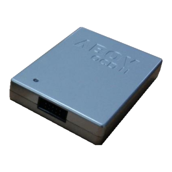
MC97F60128 ABOV Semiconductor Co., Ltd. 1.3.3 Programmer Single programmer : E-PGM+ It programs MCU device directly. DSDA DSCL RUNFLAG Figure 1.3 E-PGM+(Single writer) - Page 9 MC97F60128 ABOV Semiconductor Co., Ltd. OCD emulator : OCD-II It can write code to MCU device too, because OCD debugger supports ISP (In System Programming).It does not require additional H/W, except developer’s target system. Gang programmer : E-GANG4 and E-GANG6 It can run PC controlled mode.
-
Page 10: Mtp Programming
ABOV Semiconductor Co., Ltd. MTP programming 1.4.1 Overview The program memory of MC97F60128 is MTP Type. This flash is accessed by serial data format. There are five pins(DSCL, DSDA, RUNFLAG, VDD, VSS) for programming/reading the flash. During programming Main chip... -
Page 11: Circuit Design Guide
MC97F60128 ABOV Semiconductor Co., Ltd. 1.4.3 Circuit Design Guide At the FLASH programming, the programming tool needs 5 signal lines that are DSCL, DSDA, RUNFLAG, VDD and VSS. When you design the PCB circuits, you should consider the usage of these signal lines for the on-board programming. -
Page 12: Block Diagram
1 channel, 8-bit 32Kbps @8kHz UART 5 channels, 8-bit 1 Output channel, 12-bit 15 Input channels, 12-bit 4 channels, 8-bit 7 channels, 8-bit 2 channels, 8-bit 6 channels 10-bit PWM for Motor 1 channel 10-bit PWM Figure 2.1 Block diagrom of MC97F60128... -
Page 13: Pin Assignment
MC97F60128 ABOV Semiconductor Co., Ltd. 3. Pin assignment P00/AN0/EINT0/BLNK P86/SEG16 P01/AN1/EINT1 P87/SEG17 P02/AN2/EINT2 P50/SEG18/RXD4 P03/AN3/EINT3 P51/SEG19/TXD4 P04/AN4/EINT4 P52/SEG20/RXD3 P05/AN5/EINT5 P53/SEG21/TXD3 P06/AN6/EINT6 P54/SEG22/SS1 P07/AN7/EINT7 P55/SEG23/SCK1 AVREF P56/SEG24/TXD1/SDA1/MOSI1 P90/AN12/EINTA P57/SEG25/RXD1/SCL1/MISO1 P91/AN13/EINTB VDD2 P92/AN14/EINTC MC97F60128L VSS2 P93/EINTD PB0/SEG26 (100LQFP-1414) P94/EINTE PB1/SEG27 RUNFLAG PB2/SEG28... - Page 14 MC97F60128 ABOV Semiconductor Co., Ltd. P00/AN0/EINT0/BLNK P86/SEG16 P01/AN1/EINT1 P87/SEG17 P02/AN2/EINT2 P50/SEG18/RXD4 P03/AN3/EINT3 P51/SEG19/TXD4 P04/AN4/EINT4 P52/SEG20/RXD3 P05/AN5/EINT5 P53/SEG21/TXD3 P06/AN6/EINT6 P54/SEG22/SS1 MC97F68128L P07/AN7/EINT7 P55/SEG23/SCK1 AVREF P56/SEG24/TXD1/SDA1/MOSI1 (80LQFP-1212), RUNFLAG P57/SEG25/RXD1/SCL1/MISO1 AVSS MC97F68128L14 P40/SEG29/EC0 RESETB P41/SEG30/EC1 (80LQFP-1414) P17/XOUT P42/SEG31/EC2 P16/XIN P43/SEG32/EINT10/T0O/PWM0O VSS1 P44/SEG33/EINT11/T1O/PWM1O SXIN...
- Page 15 MC97F60128 ABOV Semiconductor Co., Ltd. P00/AN0/EINT0/BLNK P52/SEG20/RXD3 P01/AN1/EINT1 P53/SEG21/TXD3 P02/AN2/EINT2 P54/SEG22/SS1 P03/AN3/EINT3 P55/SEG23/SCK1 P04/AN4/EINT4 P56/SEG24/TXD1/SDA1/MOSI1 P05/AN5/EINT5 P57/SEG25/RXD1/SCL1/MISO1 AVREF P40/SEG29/EC0 MC97F67128LB14 P41/SEG30/EC1 RUNFLAG AVSS (64LQFP-1414) P42/SEG31/EC2 RESETB P43/SEG32/EINT10/T0O/PWM0O P17/XOUT P44/SEG33/EINT11/T1O/PWM1O P16/XIN P45/SEG34/EINT12/T2O/PWM2O VSS1 P46/SEG35/BUZO SXIN P47/SEG36/SS0 SXOUT P30/SEG37/SCK0 VDD1 P31/SEG38/TXD0/SDA0/MOSI0 NOTE) On On-Chip Debugging, ISP uses P1[5:4] pin as DSDA, DSCL.
- Page 16 MC97F60128 ABOV Semiconductor Co., Ltd. P00/AN0/EINT0/BLNK P52/SEG20/RXD3 P01/AN1/EINT1 P53/SEG21/TXD3 P02/AN2/EINT2 P54/SEG22/SS1 P03/AN3/EINT3 P55/SEG23/SCK1 P04/AN4/EINT4 P56/SEG24/TXD1/SDA1/MOSI1 P05/AN5/EINT5 P57/SEG25/RXD1/SCL1/MISO1 P06/AN6/EINT6 P40/SEG29/EC0 MC97F66128LB14 P07/AN7/EINT7 P41/SEG30/EC1 AVREF (64LQFP-1414) P42/SEG31/EC2 P43/SEG32/EINT10/T0O/PWM0O P90/AN12/EINTA P44/SEG33/EINT11/T1O/PWM1O RUNFLAG RESETB P45/SEG34/EINT12/T2O/PWM2O P17/XOUT P46/SEG35/BUZO P16/XIN P47/SEG36/SS0 VSS1 P30/SEG37/SCK0 VDD1 P31/SEG38/TXD0/SDA0/MOSI0 NOTE) On On-Chip Debugging, ISP uses P1[5:4] pin as DSDA, DSCL.
-
Page 17: Package Diagram
MC97F60128 ABOV Semiconductor Co., Ltd. 4. Package Diagram Figure 4.1 100-pin LQFP-1414 Package... - Page 18 MC97F60128 ABOV Semiconductor Co., Ltd. Figure 4.2 80-Pin LQFP-1212 Package...
- Page 19 MC97F60128 ABOV Semiconductor Co., Ltd. Figure 4.3 80-Pin LQFP-1414 Package...
- Page 20 MC97F60128 ABOV Semiconductor Co., Ltd. Figure 4.4 64-Pin LQFP-1414 Package...
-
Page 21: Pin Description
MC97F60128 ABOV Semiconductor Co., Ltd. 5. Pin Description Function @RESET Shared with Name AN0/EINT0/BLNK AN1/EINT1 Port 0 is a bit-programmable I/O port which can be AN2/EINT2 configured as a schmitt-trigger input, a push-pull AN3/EINT3 output or an open-drain output. Input A pull-up resistor can be specified in 1-bit unit. - Page 22 MC97F60128 ABOV Semiconductor Co., Ltd. Function @RESET Shared with Name SEG18/RXD4 SEG19/TXD4 SEG20/RXD3 Port 5 is a bit-programmable I/O port which can be SEG21/TXD3 configured as a schmitt-trigger input, a push-pull Input output or an open-drain output. SEG22/SS1 A pull-up resistor can be specified in 1-bit unit.
- Page 23 MC97F60128 ABOV Semiconductor Co., Ltd. Function @RESET Shared with Name Port B is a bit-programmable I/O port which can be SEG26 configured as an input, a push-pull output or an SEG27 open-drain output.. Input A pull-up resistor can be specified in 1-bit unit.
- Page 24 MC97F60128 ABOV Semiconductor Co., Ltd. Function @RESET Shared with Name Timer 0 interval output Input P43/SEG32/EINT10/PWM0O Timer 1 interval output Input P44/SEG33/EINT11/PWM1O Timer 2 interval output Input P45/SEG34/EINT12/PWM2O Timer 3 interval output Input P10/SEG58/EINT13/PWM3O/EXTSP2 Timer 4 interval output Input P11/SEG59/EINT14/PWM4O...
- Page 25 MC97F60128 ABOV Semiconductor Co., Ltd. Function @RESET Shared with Name Slave 0 select input Input P47/SEG36 Slave 1 select input Input P54/SEG22 Slave 2 select input Input P36/SEG43/CSB2 Slave 3 select input Input P22/SEG47/CSB3 TXD0 UART 0 data output Input...
- Page 26 MC97F60128 ABOV Semiconductor Co., Ltd. Function @RESET Shared with Name VLC0 P73/PWM8CB/SEG4 VLC1 P72/PWM8CA/SEG3 LCD bias voltage pins Input VLC2 P71/PWM8BB/SEG2 VLC3 P70/PWM8BA/SEG1 COM0 COM1 COM2 COM3 LCD common signal outputs Input COM4 P24/SEG49/PWMOUT COM5 P25/SEG50/TRIG COM6 P26/SEG51/EC3/EXTSP0 COM7 P27/SEG52/EC4/EXTSP1...
- Page 27 MC97F60128 ABOV Semiconductor Co., Ltd. Function @RESET Shared with Name SEG33 P44/EINT11/T1O/PWM1O SEG34 P45/EINT12/T2O/PWM2O SEG35 P46/BUZO SEG36 P47/SS0 SEG37 P30/SCK0 SEG38 P31/TXD0/SDA0/MOSI0 SEG39 P32/RXD0/SCL0/MISO0 SEG40 P33/MISO2/LDACB2 SEG41 P34/MOSI2 SEG42 P35/SCK2 SEG43 P36/SS2/CSB2 SEG44 P37/MISO3/LDACB3 SEG45 P20/MOSI3 SEG46 P21/SCK3 SEG47 P22/SS3/CSB3...
- Page 28 MC97F60128 ABOV Semiconductor Co., Ltd. PIN Name Function @RESET Shared with – RESETB System reset pin with a pull-up resistor Input (Note 4) DSDA On chip debugger data input/output Input P15/SEG63/EINT9/EC6 (Note 4) DSCL On chip debugger clock input Input...
-
Page 29: Port Structures
MC97F60128 ABOV Semiconductor Co., Ltd. 6. Port Structures General Purpose I/O Port Level Shift (1.8V to ExtVDD) Level Shift (ExtVDD to 1.8V) PULL-UP REGISTER OPEN DRAIN REGISTER DATA REGISTER SUB-FUNC DATA OUTPUT SUB-FUNC ENABLE SUB-FUNC DIRECTION DIRECTION REGISTER CMOS or... -
Page 30: External Interrupt I/O Port
MC97F60128 ABOV Semiconductor Co., Ltd. External Interrupt I/O Port Level Shift (1.8V to ExtVDD) Level Shift (ExtVDD to 1.8V) PULL-UP REGISTER OPEN DRAIN REGISTER DATA REGISTER SUB-FUNC DATA OUTPUT SUB-FUNC ENABLE SUB-FUNC DIRECTION DIRECTION REGISTER EXTERNAL INTERRUPT POLARITY REG. INTERRUPT... -
Page 31: Electrical Characteristics
MC97F60128 ABOV Semiconductor Co., Ltd. 7. Electrical Characteristics Absolute Maximum Ratings Note Parameter Symbol Rating Unit – Supply Voltage -0.3~+6.5 -0.3~VDD+0.3 Voltage on any pin with respect to VSS -0.3~VDD+0.3 Maximum current output sourced by (I per I/O pin) Normal Voltage Pin Maximum current ( ∑... -
Page 32: A/D Converter Characteristics
MC97F60128 ABOV Semiconductor Co., Ltd. A/D Converter Characteristics = 1.8 – 5.5V, VDD = AVREF, VSS=AVSS=0V) = - 40 C to + 85 C, V Parameter Symbol Conditions Unit – – – – Resolution – – ±6 Integral Non-Linear –... -
Page 33: Power-On Reset Characteristics
MC97F60128 ABOV Semiconductor Co., Ltd. Power-On Reset Characteristics =-40°C ~ +85°C, VDD=1.8V ~ 5.5V, VSS=0V) Parameter Symbol Conditions Unit – – – RESET Release Level – – VDD Voltage Rising Time 0.05 30.0 V/ms – – – POR Current Table 7-5... -
Page 34: Internal Rc Oscillator Characteristics
MC97F60128 ABOV Semiconductor Co., Ltd. Internal RC Oscillator Characteristics =-40°C ~ +85°C, VDD=1.8V ~ 5.5V, VSS=0V) Parameter Symbol Conditions Unit = 2.0 – 5.5V – – Frequency = 0°C to +50°C ±1.5 With 0.1uF – – – Tolerance = -20°C to +85°C Bypass ±2.5... -
Page 35: Lcd Voltage Characteristics
MC97F60128 ABOV Semiconductor Co., Ltd. 7.10 LCD Voltage Characteristics =-40°C ~ +85°C, VDD=1.8V ~ 5.5V, VSS=0V) Parameter Symbol Conditions Unit LCDCCR=00H VDDx16/31 LCDCCR=01H VDDx16/30 LCDCCR=02H VDDx16/29 LCDCCR=03H VDDx16/28 LCDCCR=04H VDDx16/27 VDD= 2.7V LCDCCR=05H VDDx16/26 to 5.5V, VLCD LCDCCR=06H VDDx16/25 contrast... -
Page 36: Dc Characteristics
MC97F60128 ABOV Semiconductor Co., Ltd. 7.11 DC Characteristics = -40°C ~ +85°C, VDD= 1.8V ~ 5.5V, VSS= 0V, f = 12MHz) Parameter Symbol Conditions Unit – P0–P6, P9, PA, RESETB 0.8VDD – All input pins except VIH1 0.7VDD Input High Voltage P20, P33, P34, P37;... - Page 37 MC97F60128 ABOV Semiconductor Co., Ltd. All supply current items don’t include the current of an internal watch-dog timer RC (WDTRC) oscillator and a peripheral block. All supply current items include the current of the power-on reset (POR) block.
-
Page 38: Ac Characteristics
MC97F60128 ABOV Semiconductor Co., Ltd. 7.12 AC Characteristics = -40°C ~ +85°C, VDD= 1.8V ~ 5.5V) Parameter Symbol Conditions Unit – – RESETB input low width Input, VDD= 5V – – Interrupt input high, low width All interrupt, VDD= 5V... -
Page 39: Spi0/1/2/3 Characteristics
MC97F60128 ABOV Semiconductor Co., Ltd. 7.13 SPI0/1/2/3 Characteristics =-40°C– +85°C, VDD=1.8V – 5.5V) Parameter Symbol Conditions Unit – – Output Clock Pulse Period Internal SCK source – – Input Clock Pulse Period External SCK source Output Clock High, Low –... -
Page 40: Uart0/1/2/3/4 Characteristics
MC97F60128 ABOV Semiconductor Co., Ltd. 7.14 UART0/1/2/3/4 Characteristics =-40°C ~ +85°C, VDD=1.8V ~ 5.5V, f =11.1MHz) Parameter Symbol Unit Serial port clock cycle time 1250 x 16 1650 – Output data setup to clock rising edge x 13 – –... -
Page 41: I2C0/1 Characteristics
MC97F60128 ABOV Semiconductor Co., Ltd. 7.15 I2C0/1 Characteristics =-40°C ~ +85°C, VDD=1.8V ~ 5.5V) Standard Mode High-Speed Mode Parameter Symbol Unit Clock frequency – – Clock High Pulse Width SCLH – – Clock Low Pulse Width SCLL – – Bus Free Time –... -
Page 42: Data Retention Voltage In Stop Mode
MC97F60128 ABOV Semiconductor Co., Ltd. 7.16 Data Retention Voltage in Stop Mode =-40°C ~ +85°C, VDD=1.8V ~ 5.5V) Parameter Symbol Conditions Unit – – Data retention supply voltage DDDR VDDR= 1.8V, – – Data retention supply current DDDR = 25°C), Stop mode... -
Page 43: Internal Flash Rom Characteristics
MC97F60128 ABOV Semiconductor Co., Ltd. 7.17 Internal Flash Rom Characteristics =-40°C ~ +85°C, VDD=1.8V ~ 5.5V, VSS= 0V) Parameter Symbol Condition Unit – – Sector Write Time – – Sector Erase Time – – Code Write Protection Time – –... -
Page 44: Main Clock Oscillator Characteristics
MC97F60128 ABOV Semiconductor Co., Ltd. 7.19 Main Clock Oscillator Characteristics =-40°C ~ +85°C, VDD=1.8V ~ 5.5V) Oscillator Parameter Condition Unit 2.0V – 5.5V – Crystal Main oscillation frequency 2.7V – 5.5V – 12.0 1.8V – 5.5V – Ceramic Oscillator Main oscillation frequency 2.7V –... -
Page 45: Sub Clock Oscillator Characteristics
MC97F60128 ABOV Semiconductor Co., Ltd. 7.20 Sub Clock Oscillator Characteristics =-40°C ~ +85°C, VDD=1.8V ~ 5.5V) Oscillator Parameter Condition Unit Crystal Sub oscillation frequency 32.768 1.8V – 5.5V – External Clock SXIN input frequency Table 7-21 Sub Clock Oscillator Characteristics... -
Page 46: Main Oscillation Stabilization Characteristics
MC97F60128 ABOV Semiconductor Co., Ltd. 7.21 Main Oscillation Stabilization Characteristics =-40°C ~ +85°C, VDD=1.8V ~ 5.5V) Oscillator Parameter Unit ≥ 1 MHz, VDD = 2.0V~5.5V Oscillation stabilization occurs when V – – Crystal equal to the minimum oscillator voltage range. -
Page 47: Operating Voltage Range
MC97F60128 ABOV Semiconductor Co., Ltd. 7.23 Operating Voltage Range =0.4 to 10MHz) =0.4 to 10MHz) 12.0MHz 12.0MHz 4.2MHz 4.2MHz 0.4MHz 0.4MHz Supply voltage for Ceramic (V) Supply voltage for Crystal (V) Figure 7.14 Operating Voltage Range (MAIN OSC) =32 to 38KHz) 32.768KHz... -
Page 48: Recommended Circuit And Layout
MC97F60128 ABOV Semiconductor Co., Ltd. 7.24 Recommended Circuit and Layout This 0.1uF capacitor should be within 1cm from the VDD pin of MCU on the VDD VCC PCB layout. VDD1 DC Power 0.1uF 0.1uF VSS1 The MCU power line (VDD and VSS) -
Page 49: Recommended Circuit And Layout With Smps Power
MC97F60128 ABOV Semiconductor Co., Ltd. 7.25 Recommended Circuit and Layout with SMPS Power SMPS Side MCU Side SMPS Option 1. The C1 capacitor is to flatten out the voltage of the SMPS power, VCC. √ Recommended C1: 470uF/25V more. 2. The R1 and C2 are the RC filter for VDD and suppress the ripple of VCC. -
Page 50: Typical Characteristics
MC97F60128 ABOV Semiconductor Co., Ltd. 7.26 Typical Characteristics These graphs and tables provided in this section are only for design guidance and are not tested or guaranteed. In graphs or tables some data are out of specified operating range (e.g. out of specified VDD range). This is only for information and devices are guaranteed to operate properly only within the specified range. - Page 51 MC97F60128 ABOV Semiconductor Co., Ltd. 120.0 100.0 80.0 -40℃ 60.0 +25℃ +85℃ 40.0 20.0 2.5V 3.0V 3.5V 4.0V 4.5V 5.0V 5.5V Figure 7.20 SUB RUN (IDD3) Current -40℃ +25℃ +85℃ 2.5V 3.0V 3.5V 4.0V 4.5V 5.0V 5.5V Figure 7.21 SUB IDLE (IDD4) Current...
- Page 52 MC97F60128 ABOV Semiconductor Co., Ltd. 4.50 4.00 3.50 3.00 -40℃ 2.50 +25℃ 2.00 +85℃ 1.50 1.00 0.50 0.00 2.5V 3.0V 3.5V 4.0V 4.5V 5.0V 5.5V Figure 7.22 STOP (IDD5) Current...
-
Page 53: Memory
DPTR register. Program Memory can be up to 64K bytes of Program memory in a bank. MC97F60128 provides on-chip 128 Kbytes of the ISP type flash program memory, which can be read and written to. Internal data memory (IRAM) is 256 bytes and it includes the stack area. - Page 54 MC97F60128 ABOV Semiconductor Co., Ltd. FFFFH FFFFH Total 64K Bytes 128k Bytes 64K Bytes Bank 1 0000H Bank 0 Figure 8.1 Program Memory NOTE) 128 Kbytes Including Interrupt Vector Region...
-
Page 55: Data Memory
MC97F60128 ABOV Semiconductor Co., Ltd. Data Memory 40CFH Extended Upper 128 Bytes Special Function Registers Special Function Registers Internal RAM 128 Bytes 208 Bytes (Indirect Addressing) (Direct Addressing) (Indirect Addressing) 4000H Not used 1FFFH Lower 128 Bytes Internal RAM (Direct or Indirect... - Page 56 MC97F60128 ABOV Semiconductor Co., Ltd. 7F 7E 7D 7C 7B 7A 79 78 77 76 75 74 73 72 71 70 6F 6E 6D 6C 6B 6A 69 68 67 66 65 64 63 62 61 60 5F 5E 5D 5C 5B 5A 59 58...
-
Page 57: External Data Memory
MC97F60128 ABOV Semiconductor Co., Ltd. External Data Memory MC97F60128 has 8,192 bytes XRAM and XSFR. This area has no relation with RAM/FLASH. It can be read and written to through SFR with 8-bit unit. 40CFH Extended Special Function Registers 208 Bytes... -
Page 58: Sfr Map
MC97F60128 ABOV Semiconductor Co., Ltd. SFR Map 8.4.1 SFR Map Summary Reserved M8051 compatible 00H/8H 01H/9H 02H/0AH 03H/0BH 04H/0CH 05H/0DH 06H/0EH 07H/0FH XBANK FSADRH FSADRM FSADRL FIDR FMCR MODINR 0F8H PDIO BUZCR BUZDR SPWRL SPWRH XSPCR SINTCR 0F0H RSTFR PBIO... - Page 59 MC97F60128 ABOV Semiconductor Co., Ltd. 00H/08H 01H/09H 02H/0AH 03H/0BH 04H/0CH 05H/0DH 06H/0EH 07H/0FH 40C8H DAOFSCR DACIFCR DACIFCMD 40C0H DACCR PGSR DACDRL DACDRH DACBRL DACBRH VPCR SFDDNO 40B8H VPADDR1 VPADDR2 VPADDR3 VPSIZE1 VPSIZE2 VPSIZE3 VPINF1 VPINF2 DECCR DFIFOR DECDR DBDLR DODRL...
-
Page 60: Sfr Map
MC97F60128 ABOV Semiconductor Co., Ltd. 8.4.2 SFR Map @Reset Address Function Symbol P0 Data Register Stack Pointer Data Pointer Register Low Data Pointer Register High Data Pointer Register Low 1 DPL1 Data Pointer Register High 1 DPH1 – – Low Voltage Indicator Control Register LVICR –... - Page 61 MC97F60128 ABOV Semiconductor Co., Ltd. @Reset Address Function Symbol P4 Data Register – – – P9 Data Register – – – – Extended Operation Register – – – PA Data Register – – – – – PB Data Register –...
- Page 62 MC97F60128 ABOV Semiconductor Co., Ltd. @Reset Address Function Symbol P7 Data Register – – P6 Direction Register P6IO External Interrupt Polarity 0 Low Register EIPOL0L External Interrupt Polarity 0 High Register EIPOL0H External Interrupt Polarity 2 Low Register EIPOL2L External Interrupt Polarity 2 High Register...
- Page 63 MC97F60128 ABOV Semiconductor Co., Ltd. @Reset Address Function Symbol Accumulator A Register – – – PA Direction Register PAIO – – Timer 3 Control Low Register T3CRL – – – Timer 3 Control High Register T3CRH Timer 3 A Data Low Register...
- Page 64 MC97F60128 ABOV Semiconductor Co., Ltd. @Reset Address Function Symbol 4000H A/D Converter Data Low Register ADCDRL 4001H A/D Converter Data High Register ADCDRH – 4002H A/D Converter Control Low Register ADCCRL – 4003H A/D Converter Control High Register ADCCRH –...
- Page 65 MC97F60128 ABOV Semiconductor Co., Ltd. @Reset Address Function Symbol 4020H P2 Function Selection Low Register P2FSRL – – – 4021H P2 Function Selection High Register P2FSRH 4022H P3 Function Selection Low Register P3FSRL 4023H P3 Function Selection High Register P3FSRH –...
- Page 66 MC97F60128 ABOV Semiconductor Co., Ltd. @Reset Address Function Symbol 4040H USI1 Control Register 1 USI1CR1 4041H USI1 Control Register 2 USI1CR2 4042H USI1 Control Register 3 USI1CR3 – 4043H USI1 Control Register 4 USI1CR4 – – – – – –...
- Page 67 MC97F60128 ABOV Semiconductor Co., Ltd. @Reset Address Function Symbol – – – 4060H UART2 Control Register 1 UART2CR1 4061H UART2 Control Register 2 UART2CR2 – – – – 4062H UART2 Control Register 3 UART2CR3 4063H UART2 Status Register UART2ST 4064H...
- Page 68 MC97F60128 ABOV Semiconductor Co., Ltd. @Reset Address Function Symbol – – 4080H Timer 5 Control Low Register T5CRL – – – 4081H Timer 5 Control High Register T5CRH 4082H Timer 5 A Data Low Register T5ADRL 4083H Timer 5 A Data High Register...
- Page 69 MC97F60128 ABOV Semiconductor Co., Ltd. @Reset Address Function Symbol T8DLYA 40A0H Timer 8 PWM A Delay Register T8DLYB 40A1H Timer 8 PWM B Delay Register 40A2H Timer 8 PWM C Delay Register T8DLYC 40A3H Timer 8 Data Register T8DR 40A4H...
- Page 70 MC97F60128 ABOV Semiconductor Co., Ltd. @Reset Address Function Symbol 40C0H D/A Converter Control Register DACCR – – – – 40C1H Programmable Gain Selection Register PGSR 40C2H D/A Converter Data Low Register DACDRL 40C3H D/A Converter Data High Register DACDRH 40C4H...
-
Page 71: Sfr Map
MC97F60128 ABOV Semiconductor Co., Ltd. 8.4.3 SFR Map ACC (Accumulator Register) : E0H Initial value : 00H Accumulator B (B Register) : F0H Initial value : 00H B Register SP (Stack Pointer) : 81H Initial value : 07H Stack Pointer... - Page 72 MC97F60128 ABOV Semiconductor Co., Ltd. DPL (Data Pointer Register Low) : 82H Initial value : 00H Data Pointer Low DPH (Data Pointer Register High) : 83H Initial value : 00H Data Pointer High DPL1 (Data Pointer Register Low 1) : 84H...
- Page 73 MC97F60128 ABOV Semiconductor Co., Ltd. EO (Extended Operation Register) : A2H – – – – TRAP_EN DPSEL2 DPSEL1 DPSEL0 – – – – Initial value : 00H Select the Instruction (Keep always ‘0’). TRAP_EN Select MOVC @(DPTR++), A Select Software TRAP Instruction...
- Page 74 MC97F60128 ABOV Semiconductor Co., Ltd. SINTCR (System Interrupt Control Register) : F7H – – – – – – SPOVIE SPOVIFR – – – – – – Initial value : 00H SPOVIE Stack Pointer Overflow Interrupt Disable Enable When SPOVF Interrupt occurs, this bit becomes ‘1’. The flag SPOVIFR is cleared only by writing a ‘0’...
- Page 75 MC97F60128 ABOV Semiconductor Co., Ltd. MEX1 (Memory Extension Register 1) :94H CB19 CB18 CB17 CB16 NB19 NB18 NB17 NB16 Initial value : 00H CB[19:16] Current Bank NB[19:16] Next Bank NOTE) This register records the “current” and “next” memory bank numbers for program code.
- Page 76 MC97F60128 ABOV Semiconductor Co., Ltd. MEXSP (Memory Extension Register Stack Pointer) :97H – MEXSP6 MEXSP5 MEXSP4 MEXSP3 MEXSP2 MEXSP1 MEXSP0 – Initial value : 00H MEXSP[6:0] Memory Extension Stack Pointer NOTE) This register is the memory extension stack pointer. It provides for a stack depth of up to 128 bytes (Bit 7 is always 0).
-
Page 77: I/O Ports
9. I/O Ports I/O Ports The MC97F60128 has thirteen groups of I/O ports (P0 ~ PB/PD). Each port can be easily configured by software as I/O pin, internal pull-up and open-drain pin to meet various system configurations and design requirements. Also P0 ,P1, P4, P6, P9 and PA includes function that can generate interrupt according to change of state of the pin. -
Page 78: Port Function Selection Register (Pxfsr)
MC97F60128 ABOV Semiconductor Co., Ltd. 9.2.6 Port Function Selection Register (PxFSR) These registers define alternative functions of ports. Please remember that these registers should be set properly for alternative port function. A reset clears the PxFSR register to ‘00H’, which makes all pins to normal I/O ports. - Page 79 MC97F60128 ABOV Semiconductor Co., Ltd. Name Address Direction Default Description P5 Data Register P5IO P5 Direction Register P5OD 4015H (XSFR) P5 Open-drain Selection Register P5PU P5 Pull-up Resistor Selection Register P5FSRH 4027H (XSFR) P5 Function Selection High Register P5FSRL 4026H (XSFR)
-
Page 80: P0 Port
MC97F60128 ABOV Semiconductor Co., Ltd. P0 Port 9.3.1 P0 Port Description P0 is 8-bit I/O port. P0 control registers consist of P0 data register (P0), P0 direction register (P0IO), debounce enable register (P0DB), P0 pull-up resistor selection register (P0PU) and P0 open-drain selection register (P0OD). - Page 81 MC97F60128 ABOV Semiconductor Co., Ltd. P0DB (P0 Debounce Enable Register): CCH P07DB P06DB P05DB P04DB P03DB P02DB P01DB P00DB Initial value: 00H P07DB Configure Debounce of P07 Port Disable Enable P06DB Configure Debounce of P06 Port Disable Enable P05DB Configure Debounce of P05 Port...
- Page 82 MC97F60128 ABOV Semiconductor Co., Ltd. P0FSR (Port 0 Function Selection Register): 401DH (XSFR) P0FSR7 P0FSR6 P0FSR5 P0FSR4 P0FSR3 P0FSR2 P0FSR1 P0FSR0 Initial value: 00H P0FSR7 P07 Function Select I/O Port (EINT7 function possible when input) AN7 Function P0FSR6 P06 Function Select...
-
Page 83: P1 Port
MC97F60128 ABOV Semiconductor Co., Ltd. P1 Port 9.4.1 P1 Port Description P1 is 8-bit I/O port. P1 control registers consist of P1 data register (P1), P1 direction register (P1IO), debounce enable register (P1DB), P1 pull-up resistor selection register (P1PU) and P1 open-drain selection register (P1OD) . Refer to the port function selection registers for the P1 function selection. - Page 84 MC97F60128 ABOV Semiconductor Co., Ltd. P1DB (P1 Debounce Enable Register): CDH DBCLK1 DBCLK0 P15DB P14DB P13DB P12DB P11DB P10DB Initial value: 00H DBCLK Configure Debounce Clock of Port DBCLK1 DBCLK0 description fx/4 fx/4096 (External sub OSC) P15DB Configure Debounce of P15Port...
- Page 85 MC97F60128 ABOV Semiconductor Co., Ltd. P1FSRH (Port 1 Function Selection High Register): 401FH (XSFR) – – – – P1FSRH3 P1FSRH2 P1FSRH1 P1FSRH0 – – – – Initial value: 00H P1FSRH3 P17 Function Select I/O Port XOUT Function P1FSRH2 P16 Function Select...
- Page 86 MC97F60128 ABOV Semiconductor Co., Ltd. P1FSRL (Port 1 Function Selection Low Register): 401EH (XSFR) P1FSRL7 P1FSRL6 P1FSRL5 P1FSRL4 P1FSRL3 P1FSRL2 P1FSRL1 P1FSRL0 Initial value: 00H P1FSRL[7:6] P13 Function Select P1FSRL7 P1FSRL6 Description I/O Port (EINT16 function possible when input) T6O/PWM6O Function...
-
Page 87: P2 Port
MC97F60128 ABOV Semiconductor Co., Ltd. P2 Port 9.5.1 P2 Port Description P2 is 8-bit I/O port. P2 control registers consist of P2 data register (P2), P2 direction register (P2IO), P2 pull-up resistor selection register (P2PU) and P2 open-drain selection register (P2OD).Refer to the port function selection registers for the P2 function selection. - Page 88 MC97F60128 ABOV Semiconductor Co., Ltd. P2FSRH (Port 2 Function Selection High Register):4021H (XSFR) – – – P2FSRH4 P2FSRH3 P2FSRH2 P2FSRH1 P2FSRH0 – – – Initial value: 00H P2FSRH4 P27 Function select I/O Port (EXTSP1 function possible when input) COM7/SEG52 Function...
- Page 89 MC97F60128 ABOV Semiconductor Co., Ltd. P2FSRL (Port 2 Function Selection Low Register): 4020H (XSFR) SPI3_3V P2FSRL6 P2FSRL5 P2FSRL4 P2FSRL3 P2FSRL2 P2FSRL1 P2FSRL0 Initial value: 00H SPI3_3V SPI3 Input Signal (MOSI3 or MISO3) 3V Interface Selection Normal voltage interface mode for SPI3 3V interface input mode for SPI3 (When VDD >= 3V)
-
Page 90: P3 Port
MC97F60128 ABOV Semiconductor Co., Ltd. P3 Port 9.6.1 P3 Port Description P3 is 8-bit I/O port. P3 control registers consist of P3 data register (P3), P3 direction register (P3IO), P3 pull-up resistor selection register (P3PU) and open-drain selection register (P2OD). Refer to the port function selection registers for the P3 function selection. - Page 91 MC97F60128 ABOV Semiconductor Co., Ltd. P3FSRH (Port 3 Function Selection High Register): 4023H (XSFR) SPI2_3V P3FSRH6 P3FSRH5 P3FSRH4 P3FSRH3 P3FSRH2 P3FSRH1 P3FSRH0 Initial value: 00H SPI2_3V SPI2 Input Signal (MOSI2 or MISO2) 3V Interface Selection Normal voltage interface mode for SPI2 3V interface input mode for SPI2 (When VDD >= 3V)
- Page 92 MC97F60128 ABOV Semiconductor Co., Ltd. P3FSRL (Port 3 Function Selection Low Register): 4022H (XSFR) P3FSRL7 P3FSRL6 P3FSRL5 P3FSRL4 P3FSRL3 P3FSRL2 P3FSRL1 P3FSRL0 Initial value: 00H P3FSRL[7:6] P33 Function Select P3FSRL7 P3FSRL6 Description I/O Port SEG40 Function MISO2 Function Not used...
-
Page 93: P4 Port
MC97F60128 ABOV Semiconductor Co., Ltd. P4 Port 9.7.1 P4 Port Description P4 is 8-bit I/O port. P4 control registers consist of P4 data register (P4), P4 direction register (P4IO), debounce enable register (P46DB), P4 pull-up resistor selection register (P4PU) and P4 open-drain selection register (P4OD).Refer to the port function selection registers for the P4 function selection. - Page 94 MC97F60128 ABOV Semiconductor Co., Ltd. P46DB (P4/P6 Debounce Enable Register): CEH – – – P62DB P61DB P45DB P44DB P43DB – – – Initial value: 00H P62DB Configure Debounce of P62 Port Disable Enable P61DB Configure Debounce of P61 Port Disable...
- Page 95 MC97F60128 ABOV Semiconductor Co., Ltd. P4FSRH(Port 4 Function Selection High Register): 4025H (XSFR) – P4FSRH6 P4FSRH5 P4FSRH4 P4FSRH3 P4FSRH2 P4FSRH1 P4FSRH0 – Initial value: 00H P4FSRH6 P47 Function Select I/O Port (SS0 function possible when input) SEG36 Function P4FSRH[5:4] P46 Function Select...
- Page 96 MC97F60128 ABOV Semiconductor Co., Ltd. P4FSRL(Port 4 Function Selection Low Register): 4024H (XSFR) – – – P4FSRL4 P4FSRL3 P4FSRL2 P4FSRL1 P4FSRL0 – – – Initial value: 00H P4FSRL[4:3] P43 Function Select P4FSRL4 P4FSRL3 Description I/O Port (EINT10 function possible when input)
-
Page 97: P5 Port
MC97F60128 ABOV Semiconductor Co., Ltd. P5 Port 9.8.1 P5 Port Description P5 is 8-bit I/O port. P5 control registers consist of P5 data register (P5), P5 direction register (P5IO), P5 pull-up resistor selection register (P5PU) and P5 open-drain selection register (P5OD) . Refer to the port function selection registers for the P5 function selection. - Page 98 MC97F60128 ABOV Semiconductor Co., Ltd. P5FSRH (Port 5 Function Selection High Register): 4027H (XSFR) – P5FSRH6 P5FSRH5 P5FSRH4 P5FSRH3 P5FSRH2 P5FSRH1 P5FSRH0 – Initial value: 00H P5FSRH[6:5] P57 Function Select P5FSRH6 P5FSRH5 Description I/O Port SEG25 Function RXD1/SCL1/MISO1 Function Not used...
- Page 99 MC97F60128 ABOV Semiconductor Co., Ltd. P5FSRL (Port 5 Function Selection Low Register): 4026H (XSFR) – – P5FSRL5 P5FSRL4 P5FSRL3 P5FSRL2 P5FSRL1 P5FSRL0 – – Initial value: 00H P5FSRL[5:4] P53 Function Select P5FSRL5 P5FSRL4 Description I/O Port SEG21 Function TXD3 Function...
-
Page 100: P6 Port
MC97F60128 ABOV Semiconductor Co., Ltd. P6 Port 9.9.1 P6 Port Description P6 is 6-bit I/O port. P6 control registers consist of P6 data register (P6), P6 direction register (P6IO), P6 pull-up resistor selection register (P6PU) and P6 open-drain selection register (P6OD) . Refer to the port function selection registers for the P6 function selection. - Page 101 MC97F60128 ABOV Semiconductor Co., Ltd. P6FSRH (Port 6 Function Selection High Register): 4029H (XSFR) – – – – – P6FSRH2 P6FSRH1 P6FSRH0 – – – – – Initial value: 00H P6FSRH2 P65 Function Select I/O Port (RXD2 function possible when input)
- Page 102 MC97F60128 ABOV Semiconductor Co., Ltd. P6FSRL (Port 6 Function Selection Low Register): 4028H (XSFR) P6FSRL7 P6FSRL6 P6FSRL5 P6FSRL4 P6FSRL3 P6FSRL2 P6FSRL1 P6FSRL0 Initial value: 00H P6FSRL[7:6] P63 Function Select P6FSRL7 P6FSRL6 Description I/O Port (EC7 function possible when input) AN9 Function...
-
Page 103: P7 Port
MC97F60128 ABOV Semiconductor Co., Ltd. 9.10 P7 Port 9.10.1 P7 Port Description P7 is 8-bit I/O port. P7 control registers consist of P7 data register (P7), P7 direction register (P7IO), P7 pull-up resistor selection register (P7PU) and P7 open-drain selection register (P7OD) . Refer to the port function selection registers for the P7 function selection. - Page 104 MC97F60128 ABOV Semiconductor Co., Ltd. P7FSRH (Port 7 Function Selection High Register): 402BH (XSFR) – – – – P7FSRH3 P7FSRH2 P7FSRH1 P7FSRH0 – – – – Initial value: 00H P7FSRH3 P77 Function Select I/O Port COM0 Function P7FSRH2 P76 Function Select...
- Page 105 MC97F60128 ABOV Semiconductor Co., Ltd. P7FSRL (Port 7 Function Selection Low Register): 402AH (XSFR) P7FSRL7 P7FSRL6 P7FSRL5 P7FSRL4 P7FSRL3 P7FSRL2 P7FSRL1 P7FSRL0 Initial value: 00H P7FSRL[7:6] P73 Function Select P7FSRL7 P7FSRL6 Description I/O Port VLC0 Function PWM8CB Function SEG4 Function...
-
Page 106: P8 Port
MC97F60128 ABOV Semiconductor Co., Ltd. 9.11 P8 Port 9.11.1 P8 Port Description P8 is 8-bit I/O port. P8 control registers consist of P8 data register (P8), P8 direction register (P8IO), P8 pull-up resistor selection register (P8PU) and P8 open-drain selection register (P8OD) . Refer to the port function selection registers for the P8 function selection. - Page 107 MC97F60128 ABOV Semiconductor Co., Ltd. P8FSR (Port 8 Function Selection Register): 402CH (XSFR) P8FSR7 P8FSR6 P8FSR5 P8FSR4 P8FSR3 P8FSR2 P8FSR1 P8FSR0 Initial value: 00H P8FSR7 P87 Function Select I/O Port SEG17 Function P8FSR6 P86 Function Select I/O Port SEG16 Function...
-
Page 108: P9 Port
MC97F60128 ABOV Semiconductor Co., Ltd. 9.12 P9 Port 9.12.1 P9 Port Description P9 is 5-bit I/O port. P9 control registers consist of P9 data register (P9), P9 direction register (P9IO), debounce enable register (P9DB), P9 pull-up resistor selection register (P9PU) and P9 open-drain selection register (P9OD). - Page 109 MC97F60128 ABOV Semiconductor Co., Ltd. P9DB (P9 Debounce Enable Register): CFH – – – P94DB P93DB P92DB P91DB P90DB – – – Initial value: 00H P94DB Configure Debounce of P94 Port Disable Enable P93DB Configure Debounce of P93Port Disable Enable...
- Page 110 MC97F60128 ABOV Semiconductor Co., Ltd. P9FSR (Port 9 Function Selection Register): 402DH (XSFR) – – – – – P9FSR2 P9FSR1 P9FSR0 – – – – – Initial value: 00H P9FSR2 P92 Function Select I/O Port (EINTC function possible when input)
-
Page 111: Pa Port
MC97F60128 ABOV Semiconductor Co., Ltd. 9.13 PA Port 9.13.1 PA Port Description PA is 5-bit I/O port. PA control registers consist of PA data register (PA), PA direction register (PAIO), debounce enable register (PADB), PA pull-up resistor selection register (PAPU) and PA open-drain selection register (PAOD). - Page 112 MC97F60128 ABOV Semiconductor Co., Ltd. PADB (PA Debounce Enable Register): D7H – – – PA4DB PA3DB PA2DB PA1DB PA0DB – – – Initial value: 00H PA4DB Configure Debounce of PA4 Port Disable Enable PA3DB Configure Debounce of PA3Port Disable Enable...
- Page 113 MC97F60128 ABOV Semiconductor Co., Ltd. PAFSR (Port A Function Selection Register): 402EH (XSFR) – – – PAFSR4 PAFSR3 PAFSR2 PAFSR1 PAFSR0 – – – Initial value: 00H PAFSR4 PA4 Function Select I/O Port (EINTJ function possible when input) SEG57 Function...
-
Page 114: Pb Port
MC97F60128 ABOV Semiconductor Co., Ltd. 9.14 PB Port 9.14.1 PB Port Description PB is 3-bit I/O port. PB control registers consist of PB data register (PB), PB direction register (PBIO), PB pull-up resistor selection register (PBPU) and PB open-drain selection register (PBOD). Refer to the port function selection registers for the PB function selection. - Page 115 MC97F60128 ABOV Semiconductor Co., Ltd. PBFSR (Port B Function Selection Register): 402FH (XSFR) – – – – – PBFSR2 PBFSR1 PBFSR0 – – – – – Initial value: 00H PBFSR2 PB2 Function Select I/O Port SEG28 Function PBFSR1 PB1 Function Select...
-
Page 116: Pd Port
MC97F60128 ABOV Semiconductor Co., Ltd. 9.15 PD Port 9.15.1 PD Port Description PD is 5-bit I/O port. PD control registers consist of PD data register (PD), PD direction register (PDIO), PD pull-up resistor selection register (PDPU) and PD open-drain selection register (PDOD). Refer to the port function selection registers for the PD function selection. - Page 117 MC97F60128 ABOV Semiconductor Co., Ltd. PDFSR (Port A Function Selection Register): 4037H (XSFR) – – – PDFSR4 PDFSR3 PDFSR2 PDFSR1 PDFSR0 – – – Initial value: 00H PDFSR4 PD4 Function Select I/O Port SEG9 Function PDFSR3 PD3 Function Select I/O Port...
-
Page 118: Interrupt Controller
10.1 Overview The MC97F60128 supports up to 24 interrupt sources. The interrupts have separate enable register bits associated with them, allowing software control. They can also have four levels of priority assigned to them. The non-maskable interrupt source is always enabled with a higher priority than any other interrupt source and is not controllable by software. -
Page 119: External Interrupt
MC97F60128 ABOV Semiconductor Co., Ltd. 10.2 External Interrupt The external interrupt on INT5, INT16, INT21 and INT23 pins receive various interrupt request depending on the external interrupt polarity 0/2/3/4 high/low register (EIPOLxH/L) and external interrupt polarity 1 register (EIPOL1) as shown in Figure 10.1. -
Page 120: Block Diagram
MC97F60128 ABOV Semiconductor Co., Ltd. 10.3 Block Diagram UART2 Tx UART3 Tx Priority High UART4 Tx USI1 Rx USI1 Tx/I2C EIPOL0H/L EIFLAG0.0 EINT0 FLAG0 EIFLAG0.1 EINT1 FLAG1 EIFLAG0.2 EINT2 FLAG2 EIFLAG0.3 EINT3 FLAG3 EIFLAG0.4 EINT4 FLAG4 EIFLAG0.5 EINT5 FLAG5 EIFLAG0.6... -
Page 121: Interrupt Vector Table
MC97F60128 ABOV Semiconductor Co., Ltd. An interrupt request is delayed during data are written to IE, IE1, IE2, IE3, IP0L/H, IP1L/H, IP2L/H, IP3L/H and PCON register. 10.4 Interrupt Vector Table The interrupt controller supports 24 interrupt sources as shown in the Table 11-1. When interrupt is served, long call instruction (LCALL) is executed and program counter jumps to the vector address. -
Page 122: Interrupt Sequence
MC97F60128 ABOV Semiconductor Co., Ltd. 10.5 Interrupt Sequence An interrupt request is held until the interrupt is accepted or the interrupt latch is cleared to ‘0’ by a reset or an instruction. Interrupt acceptance always generates at last cycle of the instruction. So instead of fetching the current instruction, CPU executes internally LCALL instruction and saves the PC at stack. -
Page 123: Effective Timing After Controlling Interrupt Bit
MC97F60128 ABOV Semiconductor Co., Ltd. 10.6 Effective Timing after Controlling Interrupt Bit Case a) Control Interrupt Enable Register (IE, IE1, IE2, IE3) Interrupt Enable Register command After executing IE set/clear, enable register is effective. Next Instruction Next Instruction Figure 10.4... -
Page 124: Multi Interrupt
MC97F60128 ABOV Semiconductor Co., Ltd. 10.7 Multi Interrupt If two requests of different priority levels are received simultaneously, the request of higher priority level is served first. If more than one interrupt request are received, the interrupt polling sequence determines which request is served first by hardware. -
Page 125: Interrupt Enable Accept Timing
MC97F60128 ABOV Semiconductor Co., Ltd. 10.8 Interrupt Enable Accept Timing Max. 4 Machine Cycle 4 Machine Cycle System Clock Interrupt goes Active Interrupt Interrupt Processing Latched Interrupt Routine : LCALL & LJMP Figure 10.7 Interrupt Response Timing Diagram 10.9 Interrupt Service Routine Address... -
Page 126: Interrupt Timing
MC97F60128 ABOV Semiconductor Co., Ltd. 10.11 Interrupt Timing Interrupt sampled here CLP2 CLP1 CLP2 C1P1 C1P2 C2P1 C2P2 SCLK INT_SRC INTR_ACK LAST_CYC INTR_LCALL 8-Bit interrupt Vector INT_VEC {8’h00, INT_VEC} PROGA Figure 10.10 Timing Chart of Interrupt Acceptance and Interrupt Return Instruction Interrupt sources are sampled at the last cycle of a command. -
Page 127: External Interrupt Flag Register (Eiflag0, Eiflag1)
MC97F60128 ABOV Semiconductor Co., Ltd. 10.12.3 External Interrupt Flag Register (EIFLAG0, EIFLAG1) The external interrupt flag 0 register (EIFLAG0) and external interrupt flag 1 register (EIFLAG1) areset to ‘1’ when the external interrupt generating condition is satisfied. The flag is cleared when the interrupt service routine is executed. -
Page 128: Interrupt Register Description
MC97F60128 ABOV Semiconductor Co., Ltd. 10.13 Interrupt Register Description The interrupt register is used for controlling interrupt functions. Also it has external interrupt control registers. The interrupt register consists of interrupt enable register (IE), interrupt enable register 1 (IE1), interrupt enable register 2 (IE2) and interrupt enable register 3 (IE3). -
Page 129: Register Description For Interrupt
MC97F60128 ABOV Semiconductor Co., Ltd. 10.13.1 Register Description for Interrupt IE (Interrupt Enable Register): A8H – INT5E INT4E INT3E INT2E INT1E INT0E – Initial value: 00H Enable or Disable All Interrupt bits All Interrupt disable All Interrupt enable INT5E Enable or Disable External Interrupt 0 ~ 7 (EINT0 ~ EINT7) - Page 130 MC97F60128 ABOV Semiconductor Co., Ltd. IE1 (Interrupt Enable Register 1): A9H – – INT11E INT10E INT9E INT8E INT7E INT6E – – Initial value: 00H INT11E Enable or Disable SPI2 Rx FIFO full Interrupt Disable Enable INT10E Enable or Disable USI0 Tx/I2C Interrupt...
- Page 131 MC97F60128 ABOV Semiconductor Co., Ltd. IE2 (Interrupt Enable Register 2): AAH –- – INT17E INT16E INT15E INT14E INT13E INT12E – – Initial value: 00H INT17E Enable or Disable SPI2 Tx FIFO empty Interrupt Disable Enable INT16E Enable or Disable External Interrupt 8/9/18...
- Page 132 MC97F60128 ABOV Semiconductor Co., Ltd. IE3 (Interrupt Enable Register 3): ABH – – INT23E INT22E INT21E INT20E INT19E INT18E – – Initial value :00H Enable or Disable External interrupt 10 – 17 (EINT10 – EINT17) INT23E Disable Enable INT22E Enable or Disable BIT/WDT/ADC/SP OVF Interrupt...
- Page 133 MC97F60128 ABOV Semiconductor Co., Ltd. IP0L (Interrupt Priority 0 Low Register): 92H – – IP0L5 IP0L4 IP0L3 IP0L2 IP0L1 IP0L0 – – Initial value :00H IP0H (Interrupt Priority 0 High Register): 93H – – IP0H5 IP0H4 IP0H3 IP0H2 IP0H1 IP0H0 –...
- Page 134 MC97F60128 ABOV Semiconductor Co., Ltd. IP2L (Interrupt Priority 2 Low Register): 9CH – – IP2L5 IP2L4 IP2L3 IP2L2 IP2L1 IP2L0 – – Initial value :00H IP2H (Interrupt Priority 2 High Register): 9DH – – IP2H5 IP2H4 IP2H3 IP2H2 IP2H1 IP2H0 –...
- Page 135 MC97F60128 ABOV Semiconductor Co., Ltd. EIFLAG0 (External Interrupt Flag 0 Register): BAH FLAG7 FLAG6 FLAG5 FLAG4 FLAG3 FLAG2 FLAG1 FLAG0 Initial value :00H When an External Interrupt 0-7 is occurred, the flag becomes ‘1’.The flag is cleared EIFLAG0[7:0] only by writing ‘0’ to the bit. So, the flag should be cleared by software. Writing “1”...
- Page 136 MC97F60128 ABOV Semiconductor Co., Ltd. EIFLAG1 (External Interrupt Flag 1 Register): BBH T7IFR T6IFR T5IFR T4IFR T3IFR FLAG18 FLAG9 FLAG8 Initial value: 00H When T7 interrupt occurs, this bit becomes ‘1’. The flag is cleared only by writing a ‘0’...
- Page 137 MC97F60128 ABOV Semiconductor Co., Ltd. EIFLAG2 (External Interrupt Flag 2 Register): BCH FLAG17 FLAG16 FLAG15 FLAG14 FLAG13 FLAG12 FLAG11 FLAG10 Initial value :00H When an External Interrupt 10-17 is occurred, the flag becomes ‘1’.The flag is cleared EIFLAG2[7:0] only by writing ‘0’ to the bit. So, the flag should be cleared by software. Writing “1”...
- Page 138 MC97F60128 ABOV Semiconductor Co., Ltd. EIFLAG3 (External Interrupt Flag 3 Register): BDH – – – FLAGE FLAGD FLAGC FLAGB FLAGA – – – Initial value :00H When an External Interrupt A-E is occurred, the flag becomes ‘1’.The flag is cleared EIFLAG3[5:0] only by writing ‘0’...
- Page 139 MC97F60128 ABOV Semiconductor Co., Ltd. EIFLAG4 (External Interrupt Flag 4 Register): BEH – – – FLAGJ FLAGI FLAGH FLAGG FLAGF – – – Initial value :00H When an External Interrupt F-J is occurred, the flag becomes ‘1’.The flag is cleared EIFLAG4[5:0] only by writing ‘0’...
-
Page 140: Peripheral Hardware
MC97F60128 ABOV Semiconductor Co., Ltd. Peripheral Hardware 11.1 Clock Generator 11.1.1 Overview As shown in Figure 11.1, the clock generator produces the basic clock pulses which provide the system clock to be supplied to the CPU and the peripheral hardware. It contains main/sub-frequency clock oscillator. The main/sub clock operation can be easily obtained by attaching a crystal between the XIN/SXIN and XOUT/SXOUT pin, respectively. -
Page 141: Block Diagram
MC97F60128 ABOV Semiconductor Co., Ltd. 11.1.2 Block Diagram Main OSC XOUT DCLK System SCLK (fx) STOP Mode Clock Gen. (Core, System, XCLKE IRCS[2:0] Peripheral) Stabilization Time Generation Internal RC OSC BITCK[1:0] Clock (16MHz) 1/16 overflow Change WDT clock 1/32 fx/4096... -
Page 142: Register Map
MC97F60128 ABOV Semiconductor Co., Ltd. 11.1.4 Register Map Name Address Default Description SCCR System and Clock Control Register OSCCR Oscillator Control Register PLLCR Phase Locked-Loop Control Register Table 11-1 Clock Generator Register Map 11.1.5 Clock Generator Register Description The clock generator register uses clock control for system operation. The clock generation consists of system and clock control register, oscillator control register and phase locked-loop control register. - Page 143 MC97F60128 ABOV Semiconductor Co., Ltd. OSCCR (Oscillator Control Register) : C8H – – IRCS2 IRCS1 IRCS0 IRCE XCLKE SCLKE – – Initial value : 08H IRCS[2:0] Internal RC Oscillator Post-divider Selection IRCS2 IRCS1 IRCS0 Description INT-RC/32 (0.5MHz) INT-RC/16 (1MHz) INT-RC/8 (2MHz)
- Page 144 MC97F60128 ABOV Semiconductor Co., Ltd. PLLCR (Phase Locked-Loop Control Register) : D6H – – PLLSTA P1DIV1 P1DIV0 P2DIV1 P2DIV0 PLLEN – – Initial value : 00H PLLSTA PLL Locked/Unlocked Status Bit PLL currently in unlocked state PLL currently in locked state P1DIV[1:0] PLL Post 1-Divider Selection Bits (49.152MHz)
-
Page 145: Basic Interval Timer
11.2.1 Overview The MC97F60128 has one 8-bit basic interval timer that is free-run and can’t stop. Block diagram is shown in Figure 11.3. In addition, the basic interval timer generates the time base for watchdog timer counting. It also provides a basic interval timer interrupt (BITIFR). -
Page 146: Register Map
MC97F60128 ABOV Semiconductor Co., Ltd. 11.2.3 Register Map Name Address Default Description BITCNT Basic Interval Timer Counter Register BITCR Basic Interval Timer Control Register Table 11-2 Basic Interval Timer Register Map 11.2.4 Basic Interval Timer Register Description The basic interval timer register consists of basic interval timer counter register (BITCNT) and basic interval timer control register (BITCR). - Page 147 MC97F60128 ABOV Semiconductor Co., Ltd. BITCR (Basic Interval Timer Control Register) : 8BH BITIFR BITCK1 BITCK0 BITIE BCLR BCK2 BCK1 BCK0 Initial value : 01H When BIT Interrupt occurs, this bit becomes ‘1’. For clearing bit, write ‘0’ to this bit. So, BITIFR Writing “1”...
-
Page 148: Watch Dog Timer
MC97F60128 ABOV Semiconductor Co., Ltd. 11.3 Watch Dog Timer 11.3.1 Overview The watchdog timer rapidly detects the CPU malfunction such as endless looping caused by noise or something like that and resumes the CPU to the normal state. The watchdog timer signal for malfunction detection can be used as either a CPU reset or an interrupt request. -
Page 149: Block Diagram
MC97F60128 ABOV Semiconductor Co., Ltd. 11.3.3 Block Diagram clear WDT Clock To RESET WDTCNT Circuit WDTEN To interrupt WDTIFR block clear WDTDR INT_ACK WDTCL WDTRSON WDTCR Figure 11.5 Watch Dog Timer Block Diagram 11.3.4 Register Map Name Address Default Description... -
Page 150: Register Description For Watch Dog Timer
MC97F60128 ABOV Semiconductor Co., Ltd. 11.3.6 Register Description for Watch Dog Timer WDTCNT (Watch Dog Timer Counter Register: Read Case) : 8EH WDTCNT7 WDTCNT6 WDTCNT5 WDTCNT4 WDTCNT3 WDTCNT2 WDTCNT1 WDTCNT0 Initial value : 00H WDTCNT[7:0] WDT Counter WDTDR (Watch Dog Timer Data Register: Write Case) : 8EH... -
Page 151: Watch Timer
MC97F60128 ABOV Semiconductor Co., Ltd. 11.4 Watch Timer 11.4.1 Overview The watch timer has the function for RTC (Real Time Clock) operation. It is generally used for RTC design. The internal structure of the watch timer consists of the clock source select circuit, timer counter circuit, output select circuit and watch timer control register. -
Page 152: Register Map
MC97F60128 ABOV Semiconductor Co., Ltd. 11.4.3 Register Map Name Address Default Description WTCNT Watch Timer Counter Register WTDR Watch Timer Data Register WTCR Watch Timer Control Register Table 11-4 Watch Timer Register Map 11.4.4 Watch Timer Register Description The watch timer register consists of watch timer counter register (WTCNT), watch timer data register (WTDR) and watch timer control register (WTCR). - Page 153 MC97F60128 ABOV Semiconductor Co., Ltd. WTCR (Watch Timer Control Register) : 8FH – WTEN WTIE WTIFR WTIN1 WTIN0 WTCK1 WTCK0 – Initial value : 00H WTEN Control Watch Timer Disable Enable WTIE Enable or Disable Watch Timer Interrupt Disable Enable When WT Interrupt occurs, this bit becomes ‘1’.
-
Page 154: Timer 0/1/2
MC97F60128 ABOV Semiconductor Co., Ltd. 11.5 Timer 0/1/2 11.5.1 Overview The 8-bit timer 0/1/2 consists of multiplexer, timer 0/1/2 counter register, timer 0/1/2 data register, timer 0/1/2 capture data register and timer 0/1/2 control register (TnCNT, TnDR, TnCDR, TnCR). It has three operating modes: −... -
Page 155: 8-Bit Timer/Counter Mode
MC97F60128 ABOV Semiconductor Co., Ltd. 11.5.2 8-Bit Timer/Counter Mode The 8-bit timer/counter mode is selected by control register as shown in Figure 11.7. The 8-bit timer have counter and data register. The counter register is increased by internal or external clock input. -
Page 156: 8-Bit Pwm Mode
MC97F60128 ABOV Semiconductor Co., Ltd. 11.5.3 8-Bit PWM Mode The timer 0/1/2 has a high speed PWM (Pulse Width Modulation) function. In PWM mode, TnO/PWMnO pin outputs up to 8-bit resolution PWM output. This pin should be configured as a PWM output by setting the T0O/PWM0O, T1O/PWM1O and T2O/PWM2O function by P4FSRL[4:3], P4FSRH[1:0] and P4FSRH[3:2] bits. - Page 157 MC97F60128 ABOV Semiconductor Co., Ltd. PWM Mode(TnMS = 01b) Set TnEN Timer n clock TnCNT TnDR Tn Overflow Interrupt 1. TnDR = 4AH TnPWM Tn Match Interrupt 2. TnDR = 00H TnPWM Tn Match Interrupt 3. TnDR = FFH TnPWM...
-
Page 158: 8-Bit Capture Mode
MC97F60128 ABOV Semiconductor Co., Ltd. 11.5.4 8-Bit Capture Mode The timer 0/1/2 capture mode is set by TnMS[1:0] as ‘1x’. The clock source can use the internal/external clock. Basically, it has the same function as the 8-bit timer/counter mode and the interrupt occurs when TnCNT is equal to TnDR. - Page 159 MC97F60128 ABOV Semiconductor Co., Ltd. TnCDR Load TnCNT Value Count Pulse Period Up-count TIME Ext. EINT1n PIN Interrupt Request (FLAG1n) Interrupt Interval Period Figure 11.12 Input Capture Mode Operation for Timer 0/1/2 (Where n = 0, 1 and 2) TnCNT...
-
Page 160: Block Diagram
MC97F60128 ABOV Semiconductor Co., Ltd. 11.5.5 Block Diagram Clear TnOVIE To interrupt block TnOVIFR fx/2 fx/4 8-bit Timer n Counter fx/8 Clear TnCC TnCNT (8Bit) fx/32 Match signal TnMIE fx/128 Clear To interrupt fx/512 Match TnEN block TnIFR fx/2048 Comparator... -
Page 161: Register Map
MC97F60128 ABOV Semiconductor Co., Ltd. 11.5.6 Register Map Name Address Default Description TnCR D2H/DAH/DDH Timer n Control Register TnCNT D3H/DBH/DEH Timer n Counter Register TnDR D4H/DCH/DFH Timer n Data Register TnCDR D4H/DCH/DFH Timer n Capture Data Register TINTCR 4004H (XSFR) - Page 162 MC97F60128 ABOV Semiconductor Co., Ltd. TnCR (Timer n Control Register) : D2H/DAH/DDH, Where n = 0, 1 and 2 – TnEN TnMS1 TnMS0 TnCK2 TnCK1 TnCK0 TnCC – Initial value : 00H TnEN Control Timer n Timer n disable Timer n enable...
- Page 163 MC97F60128 ABOV Semiconductor Co., Ltd. TINTCR(Timer Interrupt Control Register) : 4004H (XSFR) – – T2MIE T1MIE T0MIE T2OVIE T1OVIE T0OVIE – – Initial value : 00H T2MIE Enable or Disable Timer 2 Match Interrupt Disable Enable T1MIE Enable or Disable Timer 1 Match Interrupt...
- Page 164 MC97F60128 ABOV Semiconductor Co., Ltd. TIFLAG(Timer Interrupt Flag Register) : D5H – – T2OVIFR T2IFR T1OVIFR T1IFR T0OVIFR T0IFR – – Initial value : 00H When T2 overflow interrupt occurs, this bit becomes ‘1’. The flag is cleared only by T2OVIFR writing a ‘0’...
-
Page 165: Timer 3/4/5/6
MC97F60128 ABOV Semiconductor Co., Ltd. 11.6 Timer 3/4/5/6 11.6.1 Overview The 16-bit timer 3/4/5/6 consists of multiplexer, timer 3/4/5/6 A data register high/low, timer 3/4/5/6 B data register high/low and timer 3/4/5/6 control register high/low (TnADRH, TnADRL, TnBDRH, TnBDRL, TnCRH, TnCRL). - Page 166 MC97F60128 ABOV Semiconductor Co., Ltd. ADDRESS:E3H/4079H/4081H/4089H – – – TnEN TnMIE TnMS1 TnMS0 TnCC TnCRH INITIAL VALUE : 0000_0000B – – – ADDRESS: E2H/4078H/4080H/4088H – – TnCK2 TnCK1 TnCK0 TnPOL TnECE TnCNTR TnCRL INITIAL VALUE : 0000_0000B – – 16-bit A Data Register...
-
Page 167: 16-Bit Capture Mode
MC97F60128 ABOV Semiconductor Co., Ltd. 11.6.3 16-Bit Capture Mode The 16-bit Timer 3/4/5/6 capture mode is set by TnMS[1:0] as ‘01’. The clock source can use the internal/external clock. Basically, it has the same function as the 16-bit timer/counter mode and the interrupt occurs when TnCNTH/TnCNTL is equal to TnADRH/TnADRL. - Page 168 MC97F60128 ABOV Semiconductor Co., Ltd. TnBDRH/L Load TnCNTH/L Value Count Pulse Period Up-count TIME Ext. EINT1n PIN Interrupt Request (FLAG1n) Interrupt Interval Period Figure 11.18 Input Capture Mode Operation for Timer 3/4/5/6 (where n = 3,4,5 and 6) FFFF FFFF...
-
Page 169: 16-Bit Ppg Mode
MC97F60128 ABOV Semiconductor Co., Ltd. 11.6.4 16-Bit PPG Mode The Timer 3/4/5/6 has a PPG (Programmable Pulse Generation) function. In PPG mode, T3O/PWM3O, T4O/PWM4O, T5O/PWM5O and T6O/PWM6O pin outputs up to 16-bit resolution PWM output. This pin should be configured as a PWM output by setting P1FSR[1:0] to ‘01’, P1FSR[2] to ‘1’, P1FSR[3] to ‘1’... - Page 170 MC97F60128 ABOV Semiconductor Co., Ltd. Repeat Mode(TnMS = 11b) and "Start High"(TnPOL = 0b). Clear and Start Set TnEN Timer n clock Counter TnADRH/L Tn Interrupt 1. TnBDRH/L(5) < TnADRH/L PWMnO B Match A Match 2. TnBDRH/L >= TnADRH/L PWMnO A Match 3.
-
Page 171: Block Diagram
MC97F60128 ABOV Semiconductor Co., Ltd. 11.6.5 Block Diagram 16- bit A Data Register TnADRH / TnADRL A Match Reload TnCC TnEN TnECE TnCK[2:0] TnMIE Buffer Register A To other block Clear Edge To interrupt Detector A Match block TnIFR fx/1... -
Page 172: Register Map
MC97F60128 ABOV Semiconductor Co., Ltd. 11.6.6 Register Map Name Address Default Description TnCRH E3H/4079H/4081H/4089H Timer n Control High Register TnCRL E2H/4078H/4080H/4088H Timer n Control Low Register TnADRH E5H/407BH/4083H/408BH Timer n A Data High Register TnADRL E4H/407AH/4082H/408AH Timer n A Data Low Register... -
Page 173: Register Description For Timer/Counter 3/4/5/6
MC97F60128 ABOV Semiconductor Co., Ltd. 11.6.8 Register Description for Timer/Counter 3/4/5/6 TnADRH (Timer n A data High Register) : E5H/407BH/4083H/408BH (where n = 3,4,5 and 6) TnADRH7 TnADRH6 TnADRH5 TnADRH4 TnADRH3 TnADRH2 TnADRH1 TnADRH0 Initial value : FFH TnADRH[7:0] Tn A Data High Byte... - Page 174 MC97F60128 ABOV Semiconductor Co., Ltd. TnCRH (Timer n Control High Register) : E3H/4079H/4081H/4089H (where n = 3,4,5 and 6) – – – TnEN TnMIE TnMS1 TnMS0 TnCC – – – Initial value : 00H TnEN Control Timer n Timer n disable...
- Page 175 MC97F60128 ABOV Semiconductor Co., Ltd. TnCRL (Timer n Control Low Register) : E2H/4078H/4080H/4088H (where n = 3,4,5 and 6) – – TnCK2 TnCK1 TnCK0 TnPOL TnECE TnCNTR – – Initial value : 00H TnCK[2:0] Select Timer n clock source. fx is main system clock frequency...
-
Page 176: Timer 7/8
MC97F60128 ABOV Semiconductor Co., Ltd. 11.7 Timer 7/8 11.7.1 Overview Timer 7 and timer 8 can be used either two 8-bit timer/counter or one 16-bit timer/counter with combine them. Each 8- bit timer/event counter module has multiplexer, comparator, 8-bit timer data register, 8-bit counter register, control register and capture data register (T7CNT, T7DR, T7CAPR, T7CR, T8CNT, T8DR, T8CAPR, T8CR). -
Page 177: 8-Bit Timer/Counter 7/8 Mode
MC97F60128 ABOV Semiconductor Co., Ltd. 11.7.2 8-Bit Timer/Counter 7/8 Mode The 8-bit timer/counter mode is selected by control register as shown in Figure 11.23. The two 8-bit timers have each counter and data register. The counter register is increased by internal or external clock input. -
Page 178: 16-Bit Timer/Counter 7 Mode
MC97F60128 ABOV Semiconductor Co., Ltd. 11.7.3 16-Bit Timer/Counter 7 Mode The 16-bit timer/counter mode is selected by control register as shown in Figure 11.24. The 16-bit timer have counter and data register. The counter register is increased by internal or external clock input. -
Page 179: 8-Bit Timer 7/8 Capture Mode
MC97F60128 ABOV Semiconductor Co., Ltd. 11.7.4 8-Bit Timer 7/8 Capture Mode The 8-bit Capture 7 and 8 mode is selected by control register as shown in Figure 11.25. The timer 7/8 capture mode is set by T7MS, T8MS as ‘1’. The clock source can use the internal/external clock. - Page 180 MC97F60128 ABOV Semiconductor Co., Ltd. ADDRESS:4090H (XSFR) T7EN T7IE T7MS T7CK2 T7CK1 T7CK0 T7CN T7ST T7CR INITIAL VALUE : 0000_0000B ADDRESS:4092H (XSFR) 16BIT T8MS T8CN T8ST T8CK3 T8CK2 T8CK1 T8CK0 T8CR INITIAL VALUE : 0000_0000B FLAG18 To interrupt (EIFLAG1.2) block...
-
Page 181: 16-Bit Timer 7 Capture Mode
MC97F60128 ABOV Semiconductor Co., Ltd. 11.7.5 16-Bit Timer 7 Capture Mode The 16-bit Capture mode is selected by control register as shown in Figure 11.26. The 16-bit capture mode is the same operation as 8-bit capture mode, except that the timer register uses 16 bits. The 16-bit timer 7 capture mode is set by T7MS, T8MS as ‘1’. -
Page 182: 10-Bit Timer 8 Pwm Mode
MC97F60128 ABOV Semiconductor Co., Ltd. 11.7.6 10-Bit Timer 8 PWM Mode The timer 8 has a high speed PWM (Pulse Width Modulation) function. In PWM mode, the 6-channel pins output up to 10-bit resolution PWM output. This pin should be configured as a PWM output by set PWM8E to ‘1’. When the value of 2bit +T8CNT and T8PPRH/L are identical in timer 8, a period match signal is generated and the interrupt of timer 8 occurs. - Page 183 MC97F60128 ABOV Semiconductor Co., Ltd. ADDRESS:4092H (XSFR) 16BIT T8MS T8CN T8ST T8CK3 T8CK2 T8CK1 T8CK0 T8CR INITIAL VALUE : 0000_0000B ADDRESS:4093H (XSFR) PWM8E ESYNC BMOD PHLT UPDT UALL NOPS1 NOPS0 T8PCR1 INITIAL VALUE : 0000_0000B ADDRESS:4094H (XSFR) – FORCA PAAOE...
- Page 184 MC97F60128 ABOV Semiconductor Co., Ltd. ADDRESS:4092H (XSFR) 16BIT T8MS T8CN T8ST T8CK3 T8CK2 T8CK1 T8CK0 T8CR INITIAL VALUE : 0000_0000B ADDRESS:4093H (XSFR) PWM8E ESYNC BMOD PHLT UPDT UALL NOPS1 NOPS0 T8PCR1 INITIAL VALUE : 0000_0000B ADDRESS:4094H (XSFR) – FORCA PAAOE PABOE PBAOE PBBOE PCAOE PCBOE...
- Page 185 MC97F60128 ABOV Semiconductor Co., Ltd. Source Clock T8CNT P61/PWM8AA POLAA = 1 P61/PWM8AA POLAA = 0 Duty Cycle(1+80 )X250ns = 32.25us )X250ns = 256us 3.9kHz Period Cycle(1+3FF T8PPRH(2 Bit) T8PPRL(8 Bit) T8CR = 00 T8PPRH = 03 T8PPRL = FF...
- Page 186 MC97F60128 ABOV Semiconductor Co., Ltd. Update period & duty register value at once The period and duty of PWM comes to move from temporary registers to T8PPRH/L (PWM Period Register) and T8ADRH/L,T8BDRH/L,T8CDRH/L (PWM Duty Register) when always period match occurs. If you want that the period and duty is immediately changed, the UPDT bit in the T8PCR1 register must set to ‘1’.
- Page 187 MC97F60128 ABOV Semiconductor Co., Ltd. T8CR = 03 (2us) T8PPRH = 00 T8PPRL = 0B T8ADRH = 00 Start down Counter Start up Counter Duty match Duty match T8ADRL = 05 detect detect Source Clock T8CNT 00 01 02 03 04...
- Page 188 MC97F60128 ABOV Semiconductor Co., Ltd. External Sync If using ESYNC bit of T8PCR1 register, it is possible to synchronize the output of PWM from external signal. If ESYNC bit sets to ‘1’, the external signal moves to PWM module through the BLNK pin. If BLNK signal is on rising edge, immediately PWM output become HIGH-Z.
- Page 189 MC97F60128 ABOV Semiconductor Co., Ltd. FORCE Drive ALL Channel with A-ch mode If FORCA bit sets to ‘1’, it is possible to enable or disable all PWM output pins through PWM outputs which occur from A-ch duty counter. It is noted that the inversion outputs of A, B, C channel have the same A-ch output waveform.
- Page 190 MC97F60128 ABOV Semiconductor Co., Ltd. FORCE 6-Ch Drive If FORCA bit sets to ‘0’, it is possible to enable or disable PWM output pin and inversion output pin generated through the duty counter of each channel. The inversion output is the reverse phase of the PWM output. A AA/AB output of the A-channel duty register, a BA/BB output of the B-channel duty register, a CA/CB output of the C-channel duty register are controlled respectively.
- Page 191 MC97F60128 ABOV Semiconductor Co., Ltd. PWM output Delay If using the T8DLYA, T8DLYB, T8DLYC register, it can delay PWM output based on the rising edge. At that time, it does not change the falling edge, so the duty is reduced as the time delay. In POLAA/BA/CA setting to ‘0’, the delay is applied to the falling edge.
- Page 192 MC97F60128 ABOV Semiconductor Co., Ltd. ADDRESS : 4094H (XSFR) T8PCR2 FORCA PAAOE PABOE PBAOE PBBOE PCAOE PCBOE INITIAL VALUE : 0-00_0000B ADDRESS : 4095H (XSFR) T8PCR3 HZCLR POLBO POLAA POLAB POLBA POLBB POLCA POLCB INITIAL VALUE : 0000_0000B ADDRESS : 40A0H (XSFR)
-
Page 193: Block Diagram
MC97F60128 ABOV Semiconductor Co., Ltd. 11.7.7 Block Diagram FLAG18 To interrupt (EIFLAG1.2) block T8MS Clear 8-bit Timer 8 Capture Register EINT18 T8CAPR (8Bit) EIPOL0L[3:2] 8-bit Timer 8 Data Register T8CK[3:0] T8DR (8Bit) Comparator fx/1 To interrupt fx/2 T8CN block Match... - Page 194 MC97F60128 ABOV Semiconductor Co., Ltd. T7ST fx/2 fx/4 16-bit Timer 7 Counter fx/8 Clear T8CNT/T7CNT (16Bit) fx/32 T7IE fx/128 Clear To interrupt fx/512 Match T7CN block T7IFR fx/2048 Comparator Clear T8DR/T7DR (16Bit) T7CK[2:0] 16-bit Timer 7 Data Register EIPOL2H[7:6] T8CAPR/T7CAPR (16Bit)
-
Page 195: Register Map
MC97F60128 ABOV Semiconductor Co., Ltd. 11.7.8 Register Map Name Address Default Description T7CR 4090H (XSFR) Timer 7 Control Register T7CNT 4091H (XSFR) Timer 7 Counter Register T7DR 4091H (XSFR) Timer 7 Data Register T7CAPR 4091H (XSFR) Timer 7 Capture Data Register... -
Page 196: Timer/Counter 7 Register Description
MC97F60128 ABOV Semiconductor Co., Ltd. 11.7.9 Timer/Counter 7 Register Description The timer/counter 7 register consists of timer 7 counter register (T7CNT), timer 7 data register (T7DR), timer 7 capture data register (T7CAPR) and timer 7 control register (T7CR). 11.7.10 Register Description for Timer/Counter 7... - Page 197 MC97F60128 ABOV Semiconductor Co., Ltd. T7CR (Timer 7 Control Register) : 4090H (XSFR) T7EN T7IE T7MS T7CK2 T7CK1 T7CK0 T7CN T7ST Initial value : 00H T7EN Control Timer 7 Timer 7 disable Timer 7 enable T7IE Enable or Disable Timer 7 Interrupt...
-
Page 198: Timer/Counter 8 Register Description
MC97F60128 ABOV Semiconductor Co., Ltd. 11.7.11 Timer/Counter 8 Register Description The timer/counter 8 register consists of timer 8 PWM period high/low register (T8PPRH/L), timer 8 PWM A duty high/low register (T8ADRH/L), timer 8 PWM B duty high/low register (T8BDRH/L), timer 8 PWM C duty high/low... - Page 199 MC97F60128 ABOV Semiconductor Co., Ltd. T8BDRH (Timer 8 PWM B Duty High Register : 6-ch PWM mode only) : 409DH (XSFR) – – – – – – T8BDRH1 T8BDRH0 – – – – – – Initial value : 00H T8BDRH[1:0]...
- Page 200 MC97F60128 ABOV Semiconductor Co., Ltd. T8DLYC (Timer 8 PWM C Delay Register : 6-ch PWM mode only) : 40A2H (XSFR) T8DLYCA3 T8DLYCA2 T8DLYCA1 T8DLYCA0 T8DLYCB3 T8DLYCB2 T8DLYCB1 T8DLYCB0 Initial value : 00H T8DLYCA[3:0] PWM8CA Delay Data (Rising edge only) T8DLYCB[3:0]...
- Page 201 MC97F60128 ABOV Semiconductor Co., Ltd. T8CR (Timer 8 Control Register) : 4092H (XSFR) 16BIT T8MS T8CN T8ST T8CK3 T8CK2 T8CK1 T8CK0 Initial value : 00H 16BIT Select Two 8-bit or 16-bit Mode for Timer 7/8 Two 8-bit Timer 7/8 16-bit Timer 7...
- Page 202 MC97F60128 ABOV Semiconductor Co., Ltd. T8PCR1 (Timer 8 PWM Control Register 1) : 4093H (XSFR) PWM8E ESYNC BMOD PHLT UPDT UALL NOPS1 NOPS0 Initial value : 00H PWM8E Control Timer 8 Mode Select timer/counter or capture mode of Timer 8...
- Page 203 MC97F60128 ABOV Semiconductor Co., Ltd. T8PCR2 (Timer 8 PWM Control Register 2) : 4094H (XSFR) – FORCA PAAOE PABOE PBAOE PBBOE PCAOE PCBOE – Initial value : 00H FORCA Control The PWM outputs Mode 6-channel mode (The PWM8xA/PWM8xB pins are output according to the T8xDR registers, respectively.
- Page 204 MC97F60128 ABOV Semiconductor Co., Ltd. T8PCR3 (Timer 8 PWM Control Register 3) : 4095H (XSFR) HZCLR POLBO POLAA POLAB POLBA POLBB POLCA POLCB Initial value : 00H HZCLR High-Impedance Output Clear Bit No effect Clear high-impedance output (The PWM8xA/PWM8xB pins are back to output and this bit is automatically cleared to logic ‘0’.
- Page 205 MC97F60128 ABOV Semiconductor Co., Ltd. T8ISR (Timer 8 Interrupt Status Register) : 4096H (XSFR) – – – IOVR IBTM ICMA ICMB ICMC – – – Initial value : 00H IOVR Timer 8 Compare Match or Timer 8 Overflow Interrupt Status, Write '0' to this bit for clear.
-
Page 206: 10-Bit Pwm Generator
MC97F60128 ABOV Semiconductor Co., Ltd. 11.8 10-Bit PWM Generator 11.8.1 Overview The 10-bit PWM generator consists of multiplexer, PWM A data high/low register, PWM B data high/low register, pulse generator, delay controller, shot stop controller, emergency stop controller and PWM control high/low register (PWMADRH/L, PWMBDRH/L, PWMDLYDR, NFILDR, PWMCRH/L, PWMCNTH/L). -
Page 207: 10-Bit Pwm One-Shot Mode Without Auto-Enable
MC97F60128 ABOV Semiconductor Co., Ltd. 11.8.3 10-Bit PWM One-Shot Mode Without Auto-Enable The 10-bit PWM one-shot mode without auto-enable is selected by PWMMD[1:0] bits set to “00b”. A 10-bit counter register is increased by internal clock input on operation. When the PWMCNTH/PWMCNTL is identical to the PWMADRH/PWMADRL, a match signal is generated, the PWMOUT pin is inverted and the counting is continued to “3FFH”. -
Page 208: 10-Bit Pwm One-Shot Mode With Auto-Enable
MC97F60128 ABOV Semiconductor Co., Ltd. 11.8.4 10-Bit PWM One-Shot Mode With Auto-Enable The 10-bit PWM one-shot mode with auto-enable is selected by PWMMD[1:0] bits set to “01b”. The function of the 10- bit PWM one-shot mode with auto-enable is the same as the one of the 10-bit PWM one-shot mode without auto- enable, but the 10-bit PWM generator in the 10-bit PWM one-shot mode with auto-enable is automatically enabled as PWMEN bit set to ‘1’... -
Page 209: 10-Bit Pwm Repeat Mode
MC97F60128 ABOV Semiconductor Co., Ltd. 11.8.5 10-Bit PWM Repeat Mode The 10-bit PWM repeat mode is selected by PWMMD[1:0] bits set to “1xb”. A 10-bit counter register is increased by internal clock input on operation. When the PWMCNTH/PWMCNTL is identical to the PWMADRH/PWMADRL, a match signal is generated, the PWMOUT pin is inverted and the counting is continued to “3FFH”. -
Page 210: Timing Chart Of The Valid Falling Edge By An External Pin
MC97F60128 ABOV Semiconductor Co., Ltd. 11.8.6 Timing Chart of the Valid Falling Edge by an External Pin - Noise filter function: "Start Low" (PWMPOL = 1b) and noise filter (NFILDR = 2b) PWM clock Counter PWMADRH/L TRIG Input Invalid Trigger... - Page 211 MC97F60128 ABOV Semiconductor Co., Ltd. - Emergency Stop by the falling edge trigger of the selected EXTSP0/1/2 pins: "Start Low" (PWMPOL = 1b) PWM clock Counter PWMADRH/L EMG Interrupt TRIG Input Emergency Stop Input PWMOUT Immediately Figure 11.47 Timing Chart of Emergency Stop...
-
Page 212: Block Diagram
MC97F60128 ABOV Semiconductor Co., Ltd. 11.8.7 Block Diagram PWMCK[2:0] Clear Overflow POVIFR To interrupt block fx/1 fx/2 POVIE fx/4 fx/8 Clear PWMCC 10-bit Counter PWMEN fx/16 PWMCNTH/PWMCNTL TRIGRS[1:0] fx/32 PWMMD[1:0] fx/64 PWMEN PWMPOL fx/128 Clear Pulse Match PWMOUT EMGIFR Generator... -
Page 213: Register Map
MC97F60128 ABOV Semiconductor Co., Ltd. 11.8.8 Register Map Name Address Default Description PWMCRH 40A9H (XSFR) PWM Generator Control High Register PWMCRL 40A8H (XSFR) PWM Generator Control Low Register PWMADRH 40ABH (XSFR) PWM Generator A Data High Register PWMADRL 40AAH (XSFR) -
Page 214: Register Description For 10-Bit Pwm Generator
MC97F60128 ABOV Semiconductor Co., Ltd. 11.8.10 Register Description for 10-Bit PWM Generator PWMADRH (PWM Generator A Data High Register) : 40ABH (XSFR) – – – – – – PWMADR9 PWMADR8 – – – – – – Initial value : 03H... - Page 215 MC97F60128 ABOV Semiconductor Co., Ltd. PWMCNTH (PWM Generator Counter High Register) : 40AFH (XSFR) – – – – – – PWMCNT9 PWMCNT8 – – – – – – Initial value : 00H PWMCNT[9:8] PWM Generator Counter High Byte PWMCNTL (PWM Generator Counter Low Register) : 40AEH (XSFR)
- Page 216 MC97F60128 ABOV Semiconductor Co., Ltd. PWMCRH (PWM Generator Control High Register) : 40A9H (XSFR) ESP2S1 ESP2S0 ESP1S1 ESP1S0 ESP0S1 ESP0S0 PWMCC PWMEN Initial value : 00H ESPnS[1:0] Select the external EXTSPn pin function with falling edge trigger ESPnS1 ESPnS0 Description Disable the EXTSPn pin function Enable shot stop.
- Page 217 MC97F60128 ABOV Semiconductor Co., Ltd. PWMCRL (PWM Generator Control Low Register) : 40A8H (XSFR) PWMCK2 PWMCK1 PWMCK0 PWMPOL PWMMD1 PWMMD0 TRIGRS1 TRIGRS0 Initial value : 00H PWMCK[2:0] Select PWM generator clock source. fx is system clock frequency. PWMCK2 PWMCK1 PWMCK0 Description...
- Page 218 MC97F60128 ABOV Semiconductor Co., Ltd. PGINTCR (PWM Generator Interrupt Control Register) : 4066H (XSFR) – – – – POVIE EMGIE SHTIE TRGIE – – – – Initial value : 00H POVIE Enable or Disable PWM Generator Overflow Interrupt Disable Enable...
-
Page 219: Buzzer Driver
MC97F60128 ABOV Semiconductor Co., Ltd. 11.9 Buzzer Driver 11.9.1 Overview The Buzzer consists of 6 bit counter, buzzer data register (BUZDR) and buzzer control register (BUZCR). The Square Wave (122Hz~62.5kHz @fBUZ=1MHz) is outputted through P46/SEG35/BUZO pin. The buzzer data register (BUZDR) BUZDR[5:0] controls the bsuzzer frequency (look at the following expression) and BUZDIV[1:0] selects fBUZ divided by DIV block. -
Page 220: Overview
MC97F60128 ABOV Semiconductor Co., Ltd. 11.9.2 Overview BUZEN 6-bit Up-Counter fx/1 Clear fx/2 Counter fx/4 fx/8 scaler Match fx/16 BUZO fx/32 Comparator fx/64 BUZDR BUCK[2:0] Figure 11.49 Buzzer Driver Block Diagram... -
Page 221: Register Map
MC97F60128 ABOV Semiconductor Co., Ltd. 11.9.3 Register Map Name Address Default Description BUZDR Buzzer Data Register BUZCR Buzzer Control Register Table 11-16 Buzzer Driver Register Map 11.9.4 Buzzer Driver Register Description Buzzer driver consists of buzzer data register (BUZDR) and buzzer control register (BUZCR). -
Page 222: Spi 2
11.10 SPI 2 11.10.1 Overview There is serial peripheral interface with FIFO (SPI 2) one channel in MC97F60128. The SPI 2 allows synchronous serial data transfer between the external serial devices. It can do Full-duplex communication by 4-wire (MOSI2, MISO2, SCK2, SS2), support master/slave mode, can select serial clock (SCK2) polarity, phase and whether LSB first data transfer or MSB first data transfer. -
Page 223: Data Transmit / Receive Operation
MC97F60128 ABOV Semiconductor Co., Ltd. 11.10.3 Data Transmit / Receive Operation User can use SPI 2 for serial data communication by following step Select SPI 2 operation mode(master/slave, polarity, phase) by control register SPInCRH. When the SPI 2 is configured as a Master, it selects a Slave by SS2 signal (active low). -
Page 224: Spi 2 Timing Diagram
MC97F60128 ABOV Semiconductor Co., Ltd. 11.10.5 SPI 2 Timing Diagram SCK2 (CPOL2 = 0) SCK2 (CPOL2 = 1) MISO2/MOSI2 (Output) MOSI2/MISO2 (Input) SPI2IFR Figure 11.51 SPI 2 Transmit/Receive Timing Diagram at CPHA = 0 SCK2 (CPOL2 = 0) SCK2 (CPOL2 = 1) -
Page 225: Register Map
MC97F60128 ABOV Semiconductor Co., Ltd. 11.10.6 Register Map Name Address Default Description SPI2CRH 408FH (XSFR) SPI2 Control High Register SPI2CRL 408EH (XSFR) SPI2 Control Low Register SPI2DR 407FH (XSFR) SPI2 Data Register SPI2SRH 4087H (XSFR) SPI2 Status High Register SPI2SRL... - Page 226 MC97F60128 ABOV Semiconductor Co., Ltd. SPI2SRH (SPI 2 Status High Register) : 4087H (XSFR) – – – WCOL2 SS_HIGH2 FXCH2 SPI2SSEN DOR2 – – – Initial value : 00H WCOL2 This bit is set if any data are written to the data register SPI2DR during transfer in the master mode and during the SPI2 Tx FIFO is full.
- Page 227 MC97F60128 ABOV Semiconductor Co., Ltd. SPI2SRL (SPI 2 Status Low Register) : 4086H (XSFR) – – – TXFEIFR RXFFIFR SPI2IFR TXFFF RXFEF – – – Initial value : 04H When SPI2 Tx FIFO empty Interrupt occurs, this bit becomes ‘1’. For clearing bit, write TXFEIFR ‘0’...
- Page 228 MC97F60128 ABOV Semiconductor Co., Ltd. SPI2CRH (SPI 2 Control High Register) : 408FH (XSFR) SPI2EN FLSB2 SPI2MS CPOL2 CPHA2 SPI2DSCR SPI2SCR1 SPI2SCR0 Initial value : 00H SPI2EN This bit controls the SPI 2 operation Disable SPI 2 operation Enable SPI 2 operation...
- Page 229 MC97F60128 ABOV Semiconductor Co., Ltd. SPI2CRL (SPI 2 Control Low Register) : 408EH (XSFR) – – – – – – FIFOC MSTR2 – – – – – – Initial value : 00H FIFOC SPI2 Tx/Rx FIFO and Pointer Clear Bit No effect Clear all Tx/Rx FIFO, Pointer and Control signal.
-
Page 230: Spi 3
11.11 SPI 3 11.11.1 Overview There is serial peripheral interface (SPI 3) one channel in MC97F60128. The SPI 3 allows synchronous serial data transfer between the external serial devices. It can do Full-duplex communication by 4-wire (MOSI3, MISO3, SCK3, SS3), support master/slave mode, can select serial clock (SCK3) polarity, phase and whether LSB first data transfer or MSB first data transfer. -
Page 231: Data Transmit / Receive Operation
MC97F60128 ABOV Semiconductor Co., Ltd. 11.11.3 Data Transmit / Receive Operation User can use SPI 3 for serial data communication by following step Select SPI 3 operation mode(master/slave, polarity, phase) by control register SPI3CR. When the SPI 3 is configured as a Master, it selects a Slave by SS3 signal (active low). -
Page 232: Spi 3 Timing Diagram
MC97F60128 ABOV Semiconductor Co., Ltd. 11.11.5 SPI 3 Timing Diagram SCK3 (CPOL3 = 0) SCK3 (CPOL3 = 1) MISO3/MOSI3 (Output) MOSI3/MISO3 (Input) SPI3IFR Figure 11.54 SPI 3 Transmit/Receive Timing Diagram at CPHA = 0 SCK3 (CPOL3 = 0) SCK3 (CPOL3 = 1) -
Page 233: Register Map
MC97F60128 ABOV Semiconductor Co., Ltd. 11.11.6 Register Map Name Address Default Description SPI3CR 400DH (XSFR) SPI3 Control Register SPI3DR 400EH (XSFR) SPI3 Data Register SPI3SR 400FH (XSFR) SPI3 Status Register Table 11-18 SPI 3 Register Map 11.11.7 SPI 3 Register Description... - Page 234 MC97F60128 ABOV Semiconductor Co., Ltd. SPI3SR (SPI 3 Status Register) : 400FH (XSFR) – – – SPI3IFR WCOL3 SS_HIGH3 FXCH3 SPI3SSEN – – – Initial value : 00H When SPI 3 Interrupt occurs, this bit becomes ‘1’. IF SPI 3 interrupt is enable, this bit is SPI3IFR auto cleared by INT_ACK signal.
- Page 235 MC97F60128 ABOV Semiconductor Co., Ltd. SPI3CR (SPI 3 Control Register) : 400DH (XSFR) SPI3EN FLSB3 SPI3MS CPOL3 CPHA3 SPI3DSCR SPI3SCR1 SPI3SCR0 Initial value : 00H SPI3EN This bit controls the SPI 3 operation Disable SPI 3 operation Enable SPI 3 operation...
-
Page 236: Uart2/3/4
MC97F60128 ABOV Semiconductor Co., Ltd. 11.12 UART2/3/4 11.12.1 Overview The universal asynchronous serial receiver and transmitter (UART2/3/4) is a highly flexible serial communication device. The main features are listed below. − Full Duplex Operation (Independent Serial Receive and Transmit Registers) −... -
Page 237: Block Diagram
MC97F60128 ABOV Semiconductor Co., Ltd. 11.12.2 Block Diagram To interrupt block UARTnBD WAKEIEn RXCIEn SCLK Baud Rate Generator At Stop mode WAKEn Low level RXCn detector RXDn Clock Control Recovery Data Receive Shift Register Recovery (RXSR) LOOPSn DORn/PEn/FEn UARTnDR[0] Checker... -
Page 238: Clock Generation
MC97F60128 ABOV Semiconductor Co., Ltd. 11.12.3 Clock Generation UARTnBD U2Xn SCLK (UARTnBD+1 Baud Rate SCLK Generator txclk rxclk Figure 11.57 Clock Generation Block Diagram (where n = 2,3 and 4) The clock generation logic generates the base clock for the transmitter and receiver. -
Page 239: Data Format
MC97F60128 ABOV Semiconductor Co., Ltd. 11.12.4 Data format A serial frame is defined to be one character of data bits with synchronization bits (start and stop bits) and optionally a parity bit for error detection. The UART2/3/4 supports all 30 combinations of the following as valid frame formats. -
Page 240: Parity Bit
MC97F60128 ABOV Semiconductor Co., Ltd. 11.12.5 Parity bit The parity bit is calculated by doing an exclusive-OR of all the data bits. If odd parity is used, the result of the exclusive-or is inverted. The parity bit is located between the MSB and first stop bit of a serial frame. -
Page 241: Parity Generator
MC97F60128 ABOV Semiconductor Co., Ltd. 11.12.9 Parity Generator The parity generator calculates the parity bit for the serial frame data to be sent. When parity bit is enabled (UnPM[1]=1), the transmitter control logic inserts the parity bit between the MSB and the first stop bit of the frame to be sent. -
Page 242: Receiver Flag And Interrupt
MC97F60128 ABOV Semiconductor Co., Ltd. 11.12.13 Receiver Flag and Interrupt The UART2/3/4 receiver has one flag that indicates the receiver state. The receive complete (RXCn) flag indicates whether there are unread data in the receive buffer. This flag is set when there are unread data in the receive buffer and cleared when the receive buffer is empty. -
Page 243: Asynchronous Data Reception
MC97F60128 ABOV Semiconductor Co., Ltd. 11.12.16 Asynchronous Data Reception To receive asynchronous data frame, the UART includes a clock and data recovery unit. The clock recovery logic is used for synchronizing the internally generated baud-rate clock to the incoming asynchronous serial frame on the RXDn pin. - Page 244 MC97F60128 ABOV Semiconductor Co., Ltd. When the receiver is enabled (RXEn=1), the clock recovery logic tries to find a high-to-low transition on the RXDn line, the start bit condition. After detecting high to low transition on RXDn line, the clock recovery logic uses samples 8,9 and 10 for normal mode to decide if a valid start bit is received.
-
Page 245: Register Map
MC97F60128 ABOV Semiconductor Co., Ltd. 11.12.17 Register Map Name Address Default Description UARTnCR1 4060H/4068H/4070H (XSFR) UARTn Control Register 1 UARTnCR2 4061H/4069H/4071H (XSFR) UARTn Control Register 2 UARTnCR3 4062H/406AH/4072H (XSFR) UARTn Control Register 3 UARTnST 4063H/406BH/4073H (XSFR) UARTn Status Register UARTnBD... - Page 246 MC97F60128 ABOV Semiconductor Co., Ltd. UARTnDR (UARTn Data Register) : 4065H/406DH/4075H (XSFR), Where n = 2, 3 and 4 UARTnDR7 UARTnDR6 UARTnDR5 UARTnDR4 UARTnDR3 UARTnDR2 UARTnDR1 UARTnDR0 Initial value : 00H UARTnDR [7:0] The UARTn Transmit Buffer and Receive Buffer share the same I/O address with this DATA register.
- Page 247 MC97F60128 ABOV Semiconductor Co., Ltd. UARTnCR2 (UARTn Control Register 2) : 4061H/4069H/4071H (XSFR), Where n = 2, 3 and 4 UDRIEn TXCIEn RXCIEn WAKEIEn TXEn RXEn UARTnEN U2Xn Initial value : 00H UDRIEn Interrupt enable bit for UARTn Data Register Empty...
- Page 248 MC97F60128 ABOV Semiconductor Co., Ltd. UARTnCR3 (UARTn Control Register 3) : 4062H/406AH/4072H (XSFR), Where n = 2, 3 and 4 LOOPSn USBSn UnTX8 UnRX8 Initial value : 00H LOOPSn Controls the Loop Back Mode of UARTn, for test mode Normal operation...
- Page 249 MC97F60128 ABOV Semiconductor Co., Ltd. UARTnST (UARTn Status Register) : 4063H/406BH/4073H (XSFR), Where n = 2, 3 and 4 UDREn TXCn RXCn WAKEn SOFTRSTn DORn Initial value : 80H UDREn The UDREn flag indicates if the transmit buffer (UARTnDR) is ready to receive new data.
-
Page 250: Baud Rate Setting (Example)
MC97F60128 ABOV Semiconductor Co., Ltd. 11.12.20 Baud Rate setting (example) fx=1.00MHz fx=1.8432MHz fx=2.00MHz Baud Rate UARTnBD ERROR UARTnBD ERROR UARTnBD ERROR 2400 0.2% 0.0% 0.2% 4800 0.2% 0.0% 0.2% 9600 -7.0% 0.0% 0.2% 14.4k 8.5% 0.0% -3.5% 19.2k 8.5% 0.0% -7.0%... -
Page 251: Usi0/1 (Uart + Spi + I2C)
MC97F60128 ABOV Semiconductor Co., Ltd. 11.13 USI0/1 (UART + SPI + I2C) 11.13.1 Overview The USI0/1 consists of USI0/1 control register1/2/3/4, USI0/1 status register 1/2, USI0/1 baud-rate generation register, USI0/1 data register, USI0/1 SDA hold time register, USI0/1 SCL high period register, USI0/1 SCL low period register and USI0/1 slave address register (USInCR1, USInCR2, USInCR3, USInCR4, USInST1, USInST2, USInBD, USInDR, USInSDHR, USInSCHR, USInSCLR, USInSAR). -
Page 252: Usi0/1 Uart Mode
MC97F60128 ABOV Semiconductor Co., Ltd. 11.13.2 USI0/1 UART Mode The universal synchronous and asynchronous serial receiver and transmitter (UART) is a highly flexible serial communication device. The main features are listed below. − Full Duplex Operation (Independent Serial Receive and Transmit Registers) −... -
Page 253: Usi0/1 Uart Block Diagram
MC97F60128 ABOV Semiconductor Co., Ltd. 11.13.3 USI0/1 UART Block Diagram Master SCKn Control USInMS[1:0] SCLK USInBD (fx: System clock) To interrupt block Baud Rate Generator DBLSn WAKEIEn RXCIEn Clock Sync Logic At Stop mode WAKEn Low level RXCn detector RXDn... -
Page 254: Usi0/1 Clock Generation
MC97F60128 ABOV Semiconductor Co., Ltd. 11.13.4 USI0/1 Clock Generation USInBD DBLSn SCLK (USInBD+1) Prescaling Up-Counter txclk SCLK MASTERn Edge Sync Register USInMS[1:0] Detector CPOLn SCKn rxclk Figure 11.63 Clock Generation Block Diagram (USIn, where n = 0 and 1) The clock generation logic generates the base clock for the transmitter and receiver. The USI0/1 supports four modes of clock operation and those are normal asynchronous, double speed asynchronous, master synchronous and slave synchronous mode. -
Page 255: Usi0/1 External Clock (Sckn)
MC97F60128 ABOV Semiconductor Co., Ltd. 11.13.5 USI0/1 External Clock (SCKn) External clocking is used in the synchronous mode of operation. External clock input from the SCKn pin is sampled by a synchronization logic to remove meta-stability. The output from the synchronization logic must be passed through an edge detector before it is used by the transmitter and receiver. -
Page 256: Usi0/1 Uart Data Format
MC97F60128 ABOV Semiconductor Co., Ltd. 11.13.7 USI0/1 UART Data format A serial frame is defined to be one character of data bits with synchronization bits (start and stop bits) and optionally a parity bit for error detection. The UART supports all 30 combinations of the following as valid frame formats. -
Page 257: Usi0/1 Uart Parity Bit
MC97F60128 ABOV Semiconductor Co., Ltd. 11.13.8 USI0/1 UART Parity bit The parity bit is calculated by doing an exclusive-OR of all the data bits. If odd parity is used, the result of the exclusive-O is inverted. The parity bit is located between the MSB and first stop bit of a serial frame. -
Page 258: Usi0/1 Uart Parity Generator
MC97F60128 ABOV Semiconductor Co., Ltd. 11.13.12 USI0/1 UART Parity Generator The parity generator calculates the parity bit for the serial frame data to be sent. When parity bit is enabled (USInPM1=1), the transmitter control logic inserts the parity bit between the MSB and the first stop bit of the frame to be sent. -
Page 259: Usi0/1 Uart Receiver Flag And Interrupt
MC97F60128 ABOV Semiconductor Co., Ltd. 11.13.16 USI0/1 UART Receiver Flag and Interrupt The UART receiver has one flag that indicates the receiver state. The receive complete (RXCn) flag indicates whether there are unread data in the receive buffer. This flag is set when there are unread data in the receive buffer and cleared when the receive buffer is empty. -
Page 260: Usi0/1 Asynchronous Data Reception
MC97F60128 ABOV Semiconductor Co., Ltd. 11.13.19 USI0/1 Asynchronous Data Reception To receive asynchronous data frame, the UART includes a clock and data recovery unit. The clock recovery logic is used for synchronizing the internally generated baud-rate clock to the incoming asynchronous serial frame on the RXDn pin. - Page 261 MC97F60128 ABOV Semiconductor Co., Ltd. When the receiver is enabled (RXEn=1), the clock recovery logic tries to find a high-to-low transition on the RXDn line, the start bit condition. After detecting high to low transition on RXDn line, the clock recovery logic uses samples 8, 9 and 10 for normal mode to decide if a valid start bit is received.
-
Page 262: Usi0/1 Spi Mode
MC97F60128 ABOV Semiconductor Co., Ltd. 11.13.20 USI0/1 SPI Mode The USI0/1 can be set to operate in industrial standard SPI compliant mode. The SPI mode has the following features. − Full Duplex, Three-wire synchronous data transfer − Mater and Slave Operation −... - Page 263 MC97F60128 ABOV Semiconductor Co., Ltd. SCKn (CPOLn=0) SCKn (CPOLn=1) SAMPLE MOSIn MSB First … BIT7 BIT6 BIT2 BIT1 BIT0 LSB First … BIT0 BIT1 BIT5 BIT6 BIT7 MISOn /SSn OUT (MASTER) /SSn IN (SLAVE) Figure 11.69 USI0/1 SPI Clock Formats when CPHAn=0 (where n = 0 and 1) When CPHAn=0, the slave begins to drive its MISOn output with the first data bit value when SSn goes to active low.
- Page 264 MC97F60128 ABOV Semiconductor Co., Ltd. SCKn (CPOLn=0) SCKn (CPOLn=1) SAMPLE MOSIn … MSB First BIT7 BIT6 BIT2 BIT1 BIT0 … LSB First BIT0 BIT1 BIT5 BIT6 BIT7 MISOn /SSn OUT (MASTER) /SSn IN (SLAVE) Figure 11.70 USI0/1 SPI Clock Formats when CPHAn=1 (where n = 0 and 1) When CPHAn=1, the slave begins to drive its MISOn output when SSn goes active low, but the data is not defined until the first SCKn edge.
-
Page 265: Usi0/1 Spi Block Diagram
MC97F60128 ABOV Semiconductor Co., Ltd. 11.13.22 USI0/1 SPI Block Diagram USInBD Control SCLK Baud Rate Generator (fx: System clock) MASTERn USInSSEN Edge Detector SCKn Control Controller FXCHn RXEn CPOLn CPHAn MISOn Data Receive Shift Register Rx Control Recovery (RXSR) RXCn... -
Page 266: Usi0/1 I2C Mode
MC97F60128 ABOV Semiconductor Co., Ltd. 11.13.23 USI0/1 I2C Mode The USI0/1 can be set to operate in industrial standard serial communicatin protocols mode. The I2C mode uses 2 bus lines serial data line (SDAn) and serial clock line (SCLn) to exchange data. Because both SDAn and SCLn lines are open-drain output, each line needs pull-up resistor. -
Page 267: Usi0/1 I2C Start / Repeated Start / Stop
MC97F60128 ABOV Semiconductor Co., Ltd. 11.13.25 USI0/1 I2C Start / Repeated Start / Stop One master can issue a START (S) condition to notice other devices connected to the SCLn, SDAn lines that it will use the bus. A STOP (P) condition is generated by the master to release the bus lines so that other devices can use it. -
Page 268: Usi0/1 I2C Acknowledge
MC97F60128 ABOV Semiconductor Co., Ltd. 11.13.27 USI0/1 I2C Acknowledge The acknowledge related clock pulse is generated by the master. The transmitter releases the SDAn line (HIGH) during the acknowledge clock pulse. The receiver must pull down the SDAn line during the acknowledge clock pulse so that it remains stable LOW during the HIGH period of this clock pulse. -
Page 269: Usi0/1 I2C Operation
MC97F60128 ABOV Semiconductor Co., Ltd. Wait High Start High Counting Counting Fast Device SCLOUT High Counter Reset Slow Device SCLOUT SCLn Figure 11.76 Clock Synchronization during Arbitration Procedure (USIn, where n = 0 and 1) Arbitration Process Device 1 loses... -
Page 270: Usi0/1 I2C Master Transmitter
MC97F60128 ABOV Semiconductor Co., Ltd. 11.13.30 USI0/1 I2C Master Transmitter To operate I2C in master transmitter, follow the recommended steps below. Enable I2C by setting USInMS[1:0] bits in USInCR1 and USInEN bit in USInCR2. This provides main clock to the peripheral. - Page 271 MC97F60128 ABOV Semiconductor Co., Ltd. This is ACK signal processing stage for data packet transmitted by master. I2C holds the SCLn LOW. When I2C loses bus mastership while transmitting data arbitrating other masters, the MLOSTn bit in USInST2 is set.
-
Page 272: Usi0/1 I2C Master Receiver
MC97F60128 ABOV Semiconductor Co., Ltd. 11.13.31 USI0/1 I2C Master Receiver To operate I2C in master receiver, follow the recommended steps below. Enable I2C by setting USInMS[1:0] bits in USInCR1 and USInEN bit in USInCR2. This provides main clock to the peripheral. - Page 273 MC97F60128 ABOV Semiconductor Co., Ltd. This is ACK signal processing stage for data packet transmitted by slave. I2C holds the SCLn LOW. When 1- Byte of data is received completely, I2C generates TENDn interrupt. I2C can choose one of the following cases according to the RXACKn flag in USInST2.
-
Page 274: Usi0/1 I2C Slave Transmitter
MC97F60128 ABOV Semiconductor Co., Ltd. 11.13.32 USI0/1 I2C Slave Transmitter To operate I2C in slave transmitter, follow the recommended steps below. If the main operating clock (SCLK) of the system is slower than that of SCLn, load value 0x00 into USInSDHR to make SDAn change within one system clock period from the falling edge of SCLn. -
Page 275: Usi0/1 I2C Slave Receiver
MC97F60128 ABOV Semiconductor Co., Ltd. 11.13.33 USI0/1 I2C Slave Receiver To operate I2C in slave receiver, follow the recommended steps below. If the main operating clock (SCLK) of the system is slower than that of SCLn, load value 0x00 into USInSDHR to make SDAn change within one system clock period from the falling edge of SCLn. -
Page 276: Usi0/1 I2C Block Diagram
MC97F60128 ABOV Semiconductor Co., Ltd. 11.13.34 USI0/1 I2C Block Diagram IICnIFR To interrupt block Slave Address Register USInSAR Interrupt RXACKn, GCALLn, IICnIE TENDn, STOPDn, Generator SSELn, MLOSTn, General Call And USInGCE BUSYn, TMODEn Address Detector Receive Shift Register SDAn USInDR, (Rx) -
Page 277: Register Map
MC97F60128 ABOV Semiconductor Co., Ltd. 11.13.35 Register Map Name Address Default Description USInCR1 4030H/4040H (XSFR) USIn Control Register 1 USInCR2 4031H/4041H (XSFR) USIn Control Register 2 USInCR3 4032H/4042H (XSFR) USIn Control Register 3 USInCR4 4033H/4043H (XSFR) USIn Control Register 4... - Page 278 MC97F60128 ABOV Semiconductor Co., Ltd. USInDR (USI0/1 Data Register: For UART, SPI and I2C mode) : 403CH/404CH (XSFR), n = 0 and 1 USInDR7 USInDR6 USInDR5 USInDR4 USInDR3 USInDR2 USInDR1 USInDR0 Initial value : 00H USInDR[7:0] The USIn transmit buffer and receive buffer share the same I/O address with this DATA register.
- Page 279 MC97F60128 ABOV Semiconductor Co., Ltd. USInSCLR (USI0/1 SCL Low Period Register: For I2C mode) : 403DH/404DH (XSFR), n = 0 and 1 USInSCLR7 USInSCLR6 USInSCLR5 USInSCLR4 USInSCLR3 USInSCLR2 USInSCLR1 USInSCLR0 Initial value : 3FH USInSCLR[7:0] This register defines the high period of SCL when it operates in I2C master mode.
- Page 280 MC97F60128 ABOV Semiconductor Co., Ltd. USInCR1 (USI0/1 Control Register 1: For UART, SPI and I2C mode) : 4030H/4040H (XSFR), n = 0 and 1 USInS1 USInS0 USInMS1 USInMS0 USInPM1 USInPM0 USInS2 CPOLn ORDn CPHAn Initial value : 00H USInMS[1:0] Selects operation mode of USIn...
- Page 281 MC97F60128 ABOV Semiconductor Co., Ltd. USInCR2 (USI0/1 Control Register 2: For UART, SPI and I2C mode) : 4031H/4041H (XSFR), n = 0 and 1 DRIEn TXCIEn RXCIEn WAKEIEn TXEn RXEn USInEN DBLSn Initial value : 00H DRIEn Interrupt enable bit for data register empty (only UART and SPI mode).
- Page 282 MC97F60128 ABOV Semiconductor Co., Ltd. USInCR3 (USI0/1 Control Register 3: For UART, SPI and I2C mode) : 4032H/4042H (XSFR), n = 0 and 1 MASTERn LOOPSn DISSCKn USInSSEN FXCHn USInSB USInTX8 USInRX8 Initial value : 00H MASTERn Selects master or slave in SPI and synchronous mode operation and controls the direction of SCKn pin Slave mode operation (External clock for SCK).
- Page 283 MC97F60128 ABOV Semiconductor Co., Ltd. USInCR4 (USI0/1 Control Register 4: For I2C mode) : 4033H/4043H (XSFR), n = 0 and 1 – IICnIFR TXDLYENBn IICnIE ACKnEN IMASTERn STOPCn STARTCn – Initial value : 00H This is an interrupt flag bit for I2C mode. When an interrupt occurs, this bit becomes ‘1’.
- Page 284 MC97F60128 ABOV Semiconductor Co., Ltd. USInST1 (USI0/1 Status Register 1: For UART and SPI mode) : 4038H/4048H (XSFR), n = 0 and 1 DREn TXCn RXCn WAKEn USInRST DORn Initial value : 80H DREn The DREn flag indicates if the transmit buffer (USInDR) is ready to receive new data. If DREn is ‘1’, the buffer is empty and ready to be written.
- Page 285 MC97F60128 ABOV Semiconductor Co., Ltd. USInST2 (USI0/1 Status Register 2: For I2C mode) : 4039H/4049H (XSFR), n = 0 and 1 GCALLn TENDn STOPDn SSELn MLOSTn BUSYn TMODEn RXACKn Initial value : 00H (NOTE) GCALLn This bit has different meaning depending on whether I2C is master or slave. When I2C is a master, this bit represents whether it received AACK (address ACK) from slave.
-
Page 286: Baud Rate Setting (Example)
MC97F60128 ABOV Semiconductor Co., Ltd. 11.13.38 Baud Rate setting (example) fx=1.00MHz fx=1.8432MHz fx=2.00MHz Baud Rate USI0BD/USI1BD ERROR USI0BD/USI1BD ERROR USI0BD/USI1BD ERROR 2400 0.2% 0.0% 0.2% 4800 0.2% 0.0% 0.2% 9600 -7.0% 0.0% 0.2% 14.4k 8.5% 0.0% -3.5% 19.2k 8.5% 0.0% -7.0%... -
Page 287: 12-Bit A/D Converter
MC97F60128 ABOV Semiconductor Co., Ltd. 11.14 12-Bit A/D Converter 11.14.1 Overview The analog-to-digital converter (A/D) allows conversion of an analog input signal to corresponding 12-bit digital value. The A/D module has twelve analog inputs. The output of the multiplexer is the input into the converter which generates the result through successive approximation. -
Page 288: Block Diagram
MC97F60128 ABOV Semiconductor Co., Ltd. 11.14.3 Block Diagram TRIG[2:0] ADST T3 A match signal T4 A match signal T5 A match signal Start T8 overflow event signal T8 A match event signal CKSEL[1:0] T8 B match event signal T8 C match event signal... -
Page 289: Adc Operation
MC97F60128 ABOV Semiconductor Co., Ltd. 11.14.4 ADC Operation Align bit set “0” ADCO11 ADCO10 ADCO9 ADCO8 ADCO7 ADCO6 ADCO5 ADCO4 ADCO3 ADCO2 ADCO1 ADCO0 ADCDRH7 ADCDRH6 ADCDRH5 ADCDRH4 ADCDRH3 ADCDRH2 ADCDRH1 ADCDRH0 ADCDRL7 ADCDRL6 ADCDRL5 ADCDRL4 ADCDRH[7:0] ADCDRL[7:4] ADCDRL[3:0] bits are “0”... -
Page 290: Register Map
MC97F60128 ABOV Semiconductor Co., Ltd. SET ADCCRH Select ADC Clock and Data Align Bit. SET ADCCRL ADC enable & Select AN Input Channel. Converting START Start ADC Conversion. If Conversion is completed, AFLAG is set “1” and ADC AFLAG = 1? interrupt is occurred. -
Page 291: Register Description For Adc
MC97F60128 ABOV Semiconductor Co., Ltd. 11.14.7 Register Description for ADC ADCDRH (A/D Converter Data High Register) : 4001H (XSFR) ADDM11 ADDM10 ADDM9 ADDM8 ADDM7 ADDM6 ADDM5 ADDM4 ADDL11 ADDL10 ADDL9 ADDL8 Initial value : xxH ADDM[11:4] MSB align, A/D Converter High Result (8-bit) - Page 292 MC97F60128 ABOV Semiconductor Co., Ltd. ADCCRH (A/D Converter High Register) : 4003H (XSFR) ADCIE ADCIFR TRIG2 TRIG1 TRIG0 ALIGN CKSEL1 CKSEL0 Initial value : 00H ADCIE Enable or Disable A/DC Interrupt Disable Enable When ADC interrupt occurs, this bit becomes ‘1’. For clearing bit, write ‘0’ to this bit or ADCIFR auto clear by INT_ACK signal.
- Page 293 MC97F60128 ABOV Semiconductor Co., Ltd. ADCCRL (A/D Converter Counter Low Register) : 4002H (XSFR) STBY ADST AFLAG ADSEL3 ADSEL2 ADSEL1 ADSEL0 Initial value : 00H STBY Control Operation of A/D (The ADC module is automatically disabled at stop mode) ADC module disable...
-
Page 294: 12-Bit D/A Converter
MC97F60128 ABOV Semiconductor Co., Ltd. 11.15 12-Bit D/A Converter 11.15.1 Overview The digital-to-analog converter (D/A) uses successive approximation logic to convert 12-bit digital value to an analog output level. The D/A module has six registers which are the D/A converter control register (DACCR), D/A converter data high register (DACDRH), D/A converter data low register (DACDRL), D/A converter buffer high register (DACBRH), D/A converter buffer low register (DACBRL) and programmable gain selection register (PGSR). -
Page 295: Automatically D/Ac Data Increment/Decrement
MC97F60128 ABOV Semiconductor Co., Ltd. 11.15.4 Automatically D/AC Data Increment/Decrement The “automatically D/AC data increment/decrement” function is important to remove a pop noise when voice prompt play. If this function is not embedded, a programmer have to code to reduce a pop noise on speaker. The DACDR[15:4] value increases a curret D/AC data value to 800H with “automatically D/AC data increment”... -
Page 296: Programmable Gain Controller
MC97F60128 ABOV Semiconductor Co., Ltd. 11.15.5 Programmable Gain Controller There are 11 selectable step in the programmable gain controller. The steps are -30dB, -24dB, -18dB, -12dB, -6dB, 0dB, +6dB, +12dB, +18dB, +24dB and +30dB. The gain is selected by the programmable gain register (PGSR). -
Page 297: 12-Bit External D/Ac Interface
MC97F60128 ABOV Semiconductor Co., Ltd. 11.15.6 12-Bit External D/AC Interface D/AC Interface Signal 1: DACIFEN = “1b”, MDSEL = “0”, Where n = 2 and 3 (Only CPHAn = CPOLn = “0b”) CSBn SCKn MOSIn CMD3 CMD2 CMD1 CMD0 D/AC Interface Signal 2: DACIFEN = “1b”, MDSEL = “1”, Where n = 2 and 3 (CPHAn = CPOLn = “0b” or CPHAn = CPOLn = “1b”) -
Page 298: Block Diagram
MC97F60128 ABOV Semiconductor Co., Ltd. 11.15.7 Block Diagram DAC Pin VDD1 12-bits D/A Converter [Upper 12-bits] DACIFEN MDSEL CSB Signal D/AC Buffer Clear D/AC Interface LDACB Signal High .15 .14 .13 .12 .11 .10 .9 DACBC Controller SPI2DR (8-BIT) SPI3DR (8-BIT) -
Page 299: Register Map
MC97F60128 ABOV Semiconductor Co., Ltd. 11.15.8 Register Map Name Address Default Description DACCR 40C0H (XSFR) D/A Converter Control Register PGSR 40C1H (XSFR) Programmable Gain Selection Register DACDRH 40C3H (XSFR) D/A Converter Data High Register DACDRL 40C2H (XSFR) D/A Converter Data Low Register... -
Page 300: Register Description For Dac
MC97F60128 ABOV Semiconductor Co., Ltd. 11.15.10 Register Description for DAC DACDRH (D/A Converter Data High Register) : 40C3H (XSFR) DACDR15 DACDR14 DACDR13 DACDR12 DACDR11 DACDR10 DACDR9 DACDR8 Initial value : 00H DACDR[15:8] D/A Converter High Data (8-bit) DACDRL (D/A Converter Data Low Register) : 40C2H (XSFR) - Page 301 MC97F60128 ABOV Semiconductor Co., Ltd. DACCR (D/A Converter Control Register) : 40C0H (XSFR) DACIE DACIFR ADATID DACBC FADFEN DACRLDS1 DACRLDS0 DACEN Initial value : 00H DACIE Enable or Disable D/AC Interrupt Disable Enable When D/AC Interrupt occurs, this bit becomes ‘1’. The flag is cleared only by writing a DACIFR ‘0’...
- Page 302 MC97F60128 ABOV Semiconductor Co., Ltd. PGSR (Programmable Gain Control Register) : 40C1H (XSFR) – – – – PGS3 PGS2 PGS1 PGS0 – – – – Initial value : 00H PGS[3:0] Programmable Gain Selection PGS3 PGS2 PGS1 PGS0 Description -30dB -24dB...
- Page 303 MC97F60128 ABOV Semiconductor Co., Ltd. DACIFCR (D/AC Interface Control Register) : 40C9H (XSFR) – DACIFEN LDACB3FS LDACB2FS CSB3FS CSB2FS SPISEL MDSEL – Initial value : 00H PGS[3:0] D/AC Interface Enable Bit Disable Enable LDACB3FS LDACB3 Function Selection Bit. This bit is effective only when the P3FSRH[6:5] bits are set to “00b”, the SPISEL bit is set to “1b”, the DACIFEN bit is set to “1b”...
-
Page 304: Lcd Driver
MC97F60128 ABOV Semiconductor Co., Ltd. 11.16 LCD Driver 11.16.1 Overview The LCD driver is controlled by the LCD control register (LCDCRH/L) and LCD driver contrast control register (LCDCCR). The LCLK[1:0] determines the frequency of COM signal scanning of each segment output. A RESET clears the LCD control register LCDCRH, LCDCRL and LCDCCR values to logic ‘0’. -
Page 305: Lcd Display Ram Organization
MC97F60128 ABOV Semiconductor Co., Ltd. 11.16.2 LCD Display RAM Organization Display data are stored to the display data area in the external data memory. The display data which stored to the display external data area (address 0000H-003FH) are read automatically and sent to the LCD driver by the hardware. -
Page 306: Lcd Signal Waveform
MC97F60128 ABOV Semiconductor Co., Ltd. 11.16.3 LCD Signal Waveform COM0 SEG1 1 Frame COM1 VLC0 COM0 VLC1(VLC2, VLC3) SEG4 SEG2 SEG3 VLC0 COM1 VLC1(VLC2, VLC3) VLC0 SEG1 VLC1(VLC2, VLC3) VLC0 SEG2 VLC1(VLC2, VLC3) +VLC0 +VLC1(VLC2, VLC3) COM0-SEG1 -VLC1(VLC2, VLC3) -VLC0 Figure 11.90... - Page 307 MC97F60128 ABOV Semiconductor Co., Ltd. SEG2 SEG4 SEG3 COM0 1 Frame VLC0 VLC1 COM1 COM0 VLC2(VLC3) COM2 VLC0 VLC1 COM1 VLC2(VLC3) VLC0 VLC1 COM2 VLC2(VLC3) VLC0 VLC1 SEG2 VLC2(VLC3) VLC0 VLC1 SEG3 VLC2(VLC3) +VLC0 +VLC1 +VLC2(VLC3) COM0-SEG2 -VLC2(VLC3) -VLC1 -VLC0 Figure 11.91...
- Page 308 MC97F60128 ABOV Semiconductor Co., Ltd. SEG4 SEG3 COM0 1 Frame COM1 VLC0 VLC1 COM2 COM0 VLC2(VLC3) COM3 VLC0 VLC1 COM1 VLC2(VLC3) VLC0 VLC1 COM2 VLC2(VLC3) VLC0 VLC1 SEG3 VLC2(VLC3) VLC0 VLC1 SEG4 VLC2(VLC3) +VLC0 +VLC1 +VLC2(VLC3) COM0-SEG3 -VLC2(VLC3) -VLC1 -VLC0 Figure 11.92...
- Page 309 MC97F60128 ABOV Semiconductor Co., Ltd. COM0 1 2 3 4 5 6 7 0 1 2 3 4 5 6 7 COM1 COM2 COM3 COM4 1 Frame COM5 COM6 VLC0 COM7 VLC1 COM0 VLC2 VLC3 VLC0 VLC1 COM1 VLC2 VLC3...
-
Page 310: Lcd Voltage Dividing Connection
MC97F60128 ABOV Semiconductor Co., Ltd. 11.16.4 LCD Voltage Dividing Connection (1/ 2 Bias) (1/ 2 Bias) VLCD VLCD VLC 0 VLC 0 VLC 1 VLC 1 VLC 2 VLC 2 VLC 3 VLC 3 DISP DISP LCTEN LCTEN VLC 0... - Page 311 MC97F60128 ABOV Semiconductor Co., Ltd. (1/ 2 BIAS) (1/ 2 BIAS) VLCD VLCD DISP DISP DISP LCTEN LCTEN LCTEN VLC0 VLC0 VLC1 VLC1 VLC2 VLC2 VLC3 VLC3 R ’ R ’ R ’ R ’ (1/ 3 BIAS) (1/ 3 BIAS)
- Page 312 MC97F60128 ABOV Semiconductor Co., Ltd. VLCD VLCD (Internal Resistor Bias) (Internal Resistor Bias) VLC0 VLC0 VLC 1 VLC 1 VLC 2 VLC 2 VLC3 VLC3 DISP DISP LCTEN LCTEN VLC0 VLC0 VLC1 VLC1 VLC2 VLC2 VLC3 VLC3 VLCD VLCD (External Resistor Bias )
-
Page 313: Lcd Automatic Bias Control
MC97F60128 ABOV Semiconductor Co., Ltd. 11.16.5 LCD AUTOMATIC BIAS CONTROL Bias Mode A Bias Mode B Bias Mode A Bias Mode B ● ● ● ● Figure 11.97 Bias Mode A and Bias Mode B... -
Page 314: Block Diagram
MC97F60128 ABOV Semiconductor Co., Ltd. 11.16.6 Block Diagram Port Latch SEG/Port Driver Display COM/Port Driver fLCD Timing LCDCRL Controller LCDCRH VLC0 VLC1 LCDCCR Voltage VLC2 Bias VLC3 LCDBCR Figure 11.98 LCD Circuit Block Diagram NOTE) The clock and duty for LCD driver is automatically initialized by hardware, whenever LCDCRL register data value is rewritten. -
Page 315: Register Map
MC97F60128 ABOV Semiconductor Co., Ltd. 11.16.7 Register Map Name Address Default Description LCDBCR 400CH (XSFR) LCD Automatic Bias Control Register LCDCRH 400BH (XSFR) LCD Driver Control High Register LCDCRL 400AH (XSFR) LCD Driver Control Low Register LCDCCR 4009H (XSFR) LCD Driver Contrast Control Register... - Page 316 MC97F60128 ABOV Semiconductor Co., Ltd. LCDCRL (LCD Driver Control Low Register) : 400AH (XSFR) DBS2 DBS1 DBS0 LCLK1 LCLK0 Initial value : 00H DBS[2:0] LCD Duty and Bias Select DBS2 DBS1 DBS0 Description 1/8Duty, 1/4Bias 1/6Duty, 1/4Bias 1/5Duty, 1/3Bias 1/4Duty, 1/3Bias...
- Page 317 MC97F60128 ABOV Semiconductor Co., Ltd. LCDCCR (LCD Driver Contrast Control Register) : 4009H (XSFR) LCTEN LCDCC3 LCDCC2 LCDCC1 LCDCC0 Initial value : 00H LCTEN Control LCD Driver Contrast LCD driver contrast disable LCD driver contrast enable LCDCC[3:0] VLCD0 Voltage Control when the contrast is enabled.
- Page 318 MC97F60128 ABOV Semiconductor Co., Ltd. LCDBCR (LCD Automatic Bias Control Register) : 400CH (XSFR) LCDABC BMSEL2 BMSEL1 BMSEL0 BMODEB1 BMODEB0 BMODEA1 BMODEA0 Initial value : 00H LCDABC LCD Automatic Bias Control LCD Automatic Bias is Off LCD Automatic Bias is On (LCD contrast control function is disable when LCDABC=1) Select Bias A/B Mode Time (Refer to the Figure “LCD bias automatic control”)
-
Page 319: The Fine Adpcm Decoder
MC97F60128 ABOV Semiconductor Co., Ltd. 11.17 The Fine ADPCM Decoder 11.17.1 Overview The fine ADPCM decoder has the decoder block to play voice promt and the interface block to read data of a serial flash memory. The fine ADPCM has eighteen registers which are the decoder control register (DECCR), decoder FIFO... -
Page 320: The Decoder Result Output Of The Fadpcm
MC97F60128 ABOV Semiconductor Co., Ltd. 11.17.3 The Decoder Result Output of the FADPCM The decoder result output data (DODRH/L) are a 16-bit binary format. The data will be output every decoder match signal and the first data is 8000H after clear of decoder block by DIVS bit set to ‘1’. The match signal is generated twice in the interval time which is set for a sampling frequency. -
Page 321: Serial Flash Interface By Spi2 Or Spi3
MC97F60128 ABOV Semiconductor Co., Ltd. 11.17.4 Serial Flash Interface by SPI2 or SPI3 The interface block with a serial flash memory are to automatically read the table data of voice prompt and the encoding data of the FADPCM format. One of the SPI2 and SPI3 can be selected for a serial interface with flash memory by SPICSS bit. -
Page 322: Voice Prompt Play
MC97F60128 ABOV Semiconductor Co., Ltd. 11.17.5 Voice Prompt Play The FADPCM decoder decodes the encoding data of FADPCM format every sampling frequency. The encoding data can be read from a serial flash memory through auto-interface function up to 16M-bytes. The decoding data can be played by the D/A converter. - Page 323 MC97F60128 ABOV Semiconductor Co., Ltd. - Voice prompt data fetch for play: ATRIGS[1:0] = “11b”, DUMY[3:0] = “n”, RDNO[2:0] = “Don’t care” This bit is automatically cleared to ‘0’ after being exection SFRDST MOSI SFCMD VPADDR1 VPADDR2 VPADDR3 DUMY1 DUMY2...
-
Page 324: Block Diagram
MC97F60128 ABOV Semiconductor Co., Ltd. 11.17.6 Block Diagram DCEN Clear fx/2 fx/4 DIVS 7-Bit Up-counter fx/8 DMIE Initialize fx/16 Match Signal DMIFR Comparator DECEN To interrupt block DFEIE DCLKS[1:0] Decoder Buffer DFEIFR FIFO Empty Signal >>1 Data out[7:0] FADPCM D_FIFO... -
Page 325: Register Map
MC97F60128 ABOV Semiconductor Co., Ltd. 11.17.7 Register Map Name Address Default Description DECCR 40B0H (XSFR) FADPCM Decoder Control Register DFIFOR 40B1H (XSFR) FADPCM Decoder FIFO Register DECDR 40B2H (XSFR) FADPCM Decoder Sampling Frequency Data Register DBDLR 40B3H (XSFR) FADPCM Decoder Bundle Register... -
Page 326: Register Description For Fadpcm
MC97F60128 ABOV Semiconductor Co., Ltd. 11.17.9 Register Description for FADPCM DFIFOR (FADPCM Decoder FIFO Register) : 40B1H (XSFR) DFIFOR7 DFIFOR6 DFIFOR5 DFIFOR4 DFIFOR3 DFIFOR2 DFIFOR1 DFIFOR0 Initial value : 00H DFIFOR[7:0] Decoder FIFO Data. The data goes to the decoder FIFO (8-bytes length) if data are written in this register. - Page 327 MC97F60128 ABOV Semiconductor Co., Ltd. SFCMD (Serial Flash Command Register) : 40B7H (XSFR) SFCMD7 SFCMD6 SFCMD5 SFCMD4 SFCMD3 SFCMD2 SFCMD1 SFCMD0 Initial value : 00H SFCMD[7:0] Serial Flash Command Data. VPADDR1 (Voice Prompt Address Register 1) : 40B8H (XSFR) VPAR23...
- Page 328 MC97F60128 ABOV Semiconductor Co., Ltd. VPSIZE3 (Voice Prompt Size Register 3) : 40BDH (XSFR) VPSZ7 VPSZ6 VPSZ5 VPSZ4 VPSZ3 VPSZ2 VPSZ1 VPSZ0 Initial value : 00H VPSZ[7:0] Voice Prompt Size LSB-byte. The VPSIZE[23:0] is the size of a voice prompt to play continuously in a serial flash.
- Page 329 MC97F60128 ABOV Semiconductor Co., Ltd. DECCR (FADPCM Decoder Control Register) : 40B0H (XSFR) DFEIE DMIE DFFF DECEN DIVS DCEN DCLKS1 DCLKS0 Initial value : 00H DFEIE Decoder FIFO Empty Interrupt Enable Disable Enable DMIE Decoder Match Interrupt Enable Disable Enable...
- Page 330 MC97F60128 ABOV Semiconductor Co., Ltd. VPCR (Voice Prompt Control Register) : 40C6H (XSFR) VPEDIE VPTBLIE SFRDST SPICSS VPSDEC DTRS ATRIGS1 ATRIGS0 Initial value : 00H VPEDIE Voice Prompt End Interrupt Enable Disable Enable VPTBLIE Voice Prompt Table Data Receive End Interrupt Enable...
- Page 331 MC97F60128 ABOV Semiconductor Co., Ltd. FAFLAG (FADPCM Interrupt Flag Register) : 40B6H (XSFR) – – – SFSTOP VPEDIFR VPTBLIFR DFEIFR DMIFR – – – Initial value : 00H SFSTOP Stop the Serial Flash Interface for reading voice data No effect Stop with a serial flash interface (When write, automatically cleared ‘0’...
-
Page 332: Power Down Operation
12.1 Overview The MC97F60128 has two power-down modes to minimize the power consumption of the device. In power down mode, power consumption is reduced considerably. The device provides three kinds of power saving functions, Main- IDLE, Sub-IDLE and STOP mode. In three modes, program is stopped. -
Page 333: Idle Mode
MC97F60128 ABOV Semiconductor Co., Ltd. 12.3 IDLE Mode The power control register is set to ‘01h’ to enter the IDLE Mode. In this mode, the internal oscillation circuits remain active. Oscillation continues and peripherals are operated normally but CPU stop. It is released by reset or interrupt. To be released by interrupt, interrupt should be enabled before IDLE mode. -
Page 334: Stop Mode
MC97F60128 ABOV Semiconductor Co., Ltd. 12.4 STOP Mode The power control register is set to ‘03H’ to enter the STOP Mode. In the stop mode, the selected oscillator, system clock and peripheral clock is stopped, but watch timer can be continued to operate with sub clock. With the clock frozen, all functions are stopped, but the on-chip RAM and control registers are held. -
Page 335: Release Operation Of Stop Mode
MC97F60128 ABOV Semiconductor Co., Ltd. 12.5 Release Operation of STOP Mode After STOP mode is released, the operation begins according to content of related interrupt register just before STOP mode start (Figure 12.3). If the global interrupt Enable Flag (IE.EA) is set to `1`, the STOP mode is released by the interrupt which each interrupt enable flag = `1` and the CPU jumps to the relevant interrupt service routine. -
Page 336: Register Map
MC97F60128 ABOV Semiconductor Co., Ltd. 12.6 Register Map Name Address Default Description PCON Power Control Register Table 12-2 Power Down Operation Register Map 12.7 Power Down Operation Register Description The power down operation register consists of the power control register (PCON). -
Page 337: Reset
Control Register Refer to the Peripheral Registers Table 13-1 Reset State 13.2 Reset Source The MC97F60128 has five types of reset sources. The following is the reset sources. − External RESETB − Power ON RESET (POR) − WDT Overflow Reset (In the case of WDTEN = `1`) −... -
Page 338: Reset Noise Canceller
MC97F60128 ABOV Semiconductor Co., Ltd. 13.4 RESET Noise Canceller The Figure 13.2 is the noise canceller diagram for noise cancellation of RESET. It has the noise cancellation value of about 2us (@V =5V) to the low input of system reset. -
Page 339: Power On Reset
MC97F60128 ABOV Semiconductor Co., Ltd. 13.5 Power on RESET When rising device power, the POR (Power On Reset) has a function to reset the device. If POR is used, it executes the device RESET function instead of the RESET IC or the RESET circuits. - Page 340 MC97F60128 ABOV Semiconductor Co., Ltd. Counting for config read start after POR is released Internal nPOR PAD RESETB “H” LVR_RESETB .. 27 28 BIT (for Config) 00 01 02 03 BIT (for Reset) 1us X 256 X 28h = about 10ms...
- Page 341 MC97F60128 ABOV Semiconductor Co., Ltd. :VDD Input :Internal OSC ⑥ ④ Reset Release Config Read ② ⑦ ⑤ ① ③ Figure 13.6 Boot Process WaveForm Process Description Remarks ① -No Operation ② -1st POR level Detection -about 1.4V -(INT-OSC 8MHz/8)x256x28h Delay section (=10ms) ③...
-
Page 342: External Resetb Input
MC97F60128 ABOV Semiconductor Co., Ltd. 13.6 External RESETB Input The External RESETB is the input to a Schmitt trigger. If RESETB pin is held with low for at least 10us over within the operating voltage range and stable oscillation, it is applied and the internal state is initialized. After reset state becomes ‘1’, it needs the stabilization time with 16ms and after the stable state, the internal RESET becomes ‘1’. -
Page 343: Brown Out Detector Processor
Brown Out Detector Processor The MC97F60128 has an On-chip brown-out detection circuit (BOD) for monitoring the VDD level during operation by comparing it to a fixed trigger level. The trigger level for the BOD can be selected by LVRVS[3:0] bit to be 1.60V, 2.00V, 2.10V, 2.20V,2.32V, 2.44V, 2.59V, 2.75V, 2.93V, 3.14V, 3.38V, 3.67V, 4.00V, 4.40V. -
Page 344: Lvi Block Diagram
MC97F60128 ABOV Semiconductor Co., Ltd. “H” “H” Internal nPOR “H” PAD RESETB LVR_RESETB ..27 28 00 01 02 BIT (for Config) BIT (for Reset) 1us X 256 X 28h = about 10ms Config Read 1us X 4096 X 4h = about 16ms... -
Page 345: Register Map
MC97F60128 ABOV Semiconductor Co., Ltd. 13.9 Register Map Name Address Default Description LVICR Low Voltage Indicator Control Register RSTFR Reset Flag Register LVRCR Low Voltage Reset Control Register Table 13-3 Reset Operation Register Map 13.10 Reset Operation Register Description The reset control register consists of the reset flag register (RSTFR), low voltage reset control register (LVRCR) and... -
Page 346: Register Description For Reset Operation
MC97F60128 ABOV Semiconductor Co., Ltd. 13.11 Register Description for Reset Operation RSTFR (Reset Flag Register) : E8H – – PORF EXTRF WDTRF OCDRF LVRF FPRIRF – – Initial value : 80H Power-On Reset flag bit. The bit is reset by writing ‘0’ to this bit. - Page 347 MC97F60128 ABOV Semiconductor Co., Ltd. LVRCR (Low Voltage Reset Control Register) : D8H – – LVRST LVRVS3 LVRVS2 LVRVS1 LVRVS0 LVREN – – Initial value : 00H LVRST LVR Enable when Stop Release Not effect at stop release LVR enable at stop release NOTE) When this bit is ‘1’, the LVREN bit is cleared to ‘0’...
- Page 348 MC97F60128 ABOV Semiconductor Co., Ltd. LVICR (Low Voltage Indicator Control Register) : 86H – – LVIF LVIEN LVILS3 LVILS2 LVILS1 LVILS0 – – Initial value : 00H LVIF Low Voltage Indicator Flag Bit No detection Detection LVIEN LVI Enable/Disable Disable...
-
Page 349: On-Chip Debug System
Overview 14.1.1 Description On-chip debug system (OCD2) of MC97F60128 can be used for programming the non-volatile memories and on-chip debugging. Detail descriptions for programming via the OCD2 interface can be found in the following chapter. Figure 14.1 shows a block diagram of the OCD2 interface and the On-chip Debug system. -
Page 350: Feature
MC97F60128 ABOV Semiconductor Co., Ltd. 14.1.2 Feature • Two-wire external interface: 1-wire serial clock input, 1-wire bi-directional serial data bus • Debugger Access to: − All Internal Peripheral Units − Internal data RAM − Program Counter − Flash and Data EEPROM Memories •... -
Page 351: Two-Pin External Interface
MC97F60128 ABOV Semiconductor Co., Ltd. 14.2 Two-Pin External Interface 14.2.1 Basic Transmission Packet • 10-bit packet transmission using two-pin interface. • packet consists of 8-bit data, 1-bit parity and 1-bit acknowledge. • Parity is even of ‘1’ for 8-bit data in transmitter. -
Page 352: Packet Transmission Timing
MC97F60128 ABOV Semiconductor Co., Ltd. 14.2.2 Packet Transmission Timing Data Transfer 14.2.2.1 DSDA acknowledgement acknowledgement signal from receiver signal from receiver DSCL START STOP Figure 14.3 Data Transfer on the Twin Bus Bit Transfer 14.2.2.2 DSDA DSCL data line change... -
Page 353: Start And Stop Condition
MC97F60128 ABOV Semiconductor Co., Ltd. Start and Stop Condition 14.2.2.3 DSDA DSDA DSCL DSCL START condition STOP condition Figure 14.5 Start and Stop Condition Acknowledge Bit 14.2.2.4 Data output By transmitter no acknowledge Data output By receiver acknowledge DSCL from... -
Page 354: Connection Of Transmission
MC97F60128 ABOV Semiconductor Co., Ltd. 14.2.3 Connection of Transmission Two-pin interface connection uses open-drain(wire-AND bidirectional I/O). pull - up resistors DSDA(Debugger Serial Data Line) DSCL(Debugger Serial Clock Line) RUNFLAG RUNFLAG DSCL DSDA DSCL DSDA RUNFLAG DSDA RUNFLAG DSDA RUNFLAG DSCL... -
Page 355: Flash Memory
15.1.1 Description MC97F60128 incorporates flash memory to which a program can be written, erased and overwritten while mounted on the board. The flash memory can be read by ‘MOVC’ instruction and it can be programmed in OCD, serial ISP mode or user program mode. -
Page 356: Flash Program Rom Structure
MC97F60128 ABOV Semiconductor Co., Ltd. 15.1.2 Flash Program ROM Structure 1FFFFH Sector 1023 1FF80H 1FF80H 1FF7FH Sector 1022 1FF00H 1FF00H 1FEFFH Sector 1021 1FE80H 1FE80H 1FE7FH Sector 1020 Flash Sector Address Address Sector 2 00100H 00100H 000FFH Sector 1 00080H... -
Page 357: Register Map
MC97F60128 ABOV Semiconductor Co., Ltd. 15.1.3 Register Map Name Address Direction Default Description FSADRH Flash Sector Address High Register FSADRM Flash Sector Address Middle Register FSADRL Flash Sector Address Low Register FIDR Flash Identification Register FMCR Flash Mode Control Register... -
Page 358: Register Description For Flash
MC97F60128 ABOV Semiconductor Co., Ltd. 15.1.5 Register Description for Flash FSADRH (Flash Sector Address High Register): FAH – – – – FSADRH3 FSADRH 2 FSADRH1 FSADRH0 – – – – Initial value: 00H FSADRH[3:0] Flash Sector Address High FSADRM (Flash Sector Address Middle Register): FBH... - Page 359 MC97F60128 ABOV Semiconductor Co., Ltd. FMCR (Flash Mode Control Register): FEH – – – – FMBUSY FMCR2 FMCR1 FMCR0 – – – – Initial value: 00H FMBUSY Flash Mode Busy Bit. This bit will be used for only debugger. No effect when “1” is written...
-
Page 360: Serial In-System Program (Isp) Mode
15.1.7 Protection Area (User program mode) MC97F60128 can program its own flash memory (protection area). The protection area can not be erased or programmed. The protection areas are available only when the PAEN bit is cleared to ‘0’, that is, enable protection area at the configure option 2 if it is needed. -
Page 361: Erase Mode
MC97F60128 ABOV Semiconductor Co., Ltd. 15.1.8 Erase Mode The sector erase program procedure in user program mode Page buffer clear (FMCR=0x01) Write ‘0’ to page buffer Set flash sector address register (FSADRH/FSADRM/FSADRL). Set flash identification register (FIDR). (Note) Check the UserID for to prevent the invalid work Set flash mode control register (FMCR). -
Page 362: Write Mode
MC97F60128 ABOV Semiconductor Co., Ltd. 15.1.9 Write Mode The sector Write program procedure in user program mode Page buffer clear (FMCR=0x01) Write data to page buffer Set flash sector address register (FSADRH/FSADRM/FSADRL). Set flash identification register (FIDR). (Note1) Check the UserID for to prevent the invalid work Set flash mode control register (FMCR). - Page 363 MC97F60128 ABOV Semiconductor Co., Ltd. The Byte Write program procedure in user program mode Page buffer clear (FMCR=0x01) Write data to page buffer Set flash sector address register (FSADRH/FSADRM/FSADRL). Set flash identification register (FIDR). (Note1) Check the UserID for to prevent the invalid work Set flash mode control register (FMCR).
-
Page 364: Protection For Invalid Erase/Write
MC97F60128 ABOV Semiconductor Co., Ltd. 15.1.10 Protection for Invalid Erase/Write It should be taken care to the flash erase/write programming in code. You must make preparations for invalid jump to the flash erase/write code by malfunction, noise and power off. - Page 365 MC97F60128 ABOV Semiconductor Co., Ltd. The flash sector address (FSADRH/FSADRM/FSADRL) should always keep the address of the flash which is used for data area. For example, The FSADRH/FSADRM is always 0x01/0xff” if 0x01ff00 to 0x01ffff is used for data. Overview of main...
-
Page 366: Flow Of Protection For Invalid Erase/Write
MC97F60128 ABOV Semiconductor Co., Ltd. Flow of Protection for Invalid Erase/Write 15.1.10.1 Start Work1 Decide to write/erase Set Flags on flash Work2 Check the flag for Match Write UserID1/2/3 UserID Work3 Check the UserID for Match Write/Erase Flash write/erase flash... -
Page 367: Read Mode
MC97F60128 ABOV Semiconductor Co., Ltd. 15.1.11 Read Mode The Reading program procedure in user program mode Load receive data from flash memory on MOVC instruction by indirectly addressing mode. Program Tip – reading EO,#0xF8 ;Set DPTR0 MEX2,#0x90 ;If used BANK1, set MCM and MCB is ‘1’, MEX3,#0x7F ;If used BANK0, set MCM and MCB is ‘0’,... -
Page 368: Configure Option
MC97F60128 ABOV Semiconductor Co., Ltd. Configure Option 16.1 Configure Option Control The data for configure option should be written in the configure option area (003EH – 003FH) by programmer (Writer tools). CONFIGURE OPTION 1 : ROM Address 003FH – –... -
Page 369: Appendix
MC97F60128 ABOV Semiconductor Co., Ltd. APPENDIX 17.1 Instruction Table Instructions are either1, 2 or 3bytes long as listed in the ‘Bytes’ column below. Each instruction takes either 1, 2 or 4 machine cycles to execute as listed in the following table. 1 machine cycle comprises 2 system clock cycles. - Page 370 MC97F60128 ABOV Semiconductor Co., Ltd. LOGICAL Mnemonic Description Bytes Cycles Hex code ANL A,Rn AND register to A 58-5F ANL A,dir AND direct byte to A ANL A,@Ri AND indirect memory to A 56-57 ANL A,#data AND immediate to A...
- Page 371 MC97F60128 ABOV Semiconductor Co., Ltd. DATA TRANSFER Mnemonic Description Bytes Cycles Hex code MOV A,Rn Move register to A E8-EF MOV A,dir Move direct byte to A MOV A,@Ri Move indirect memory to A E6-E7 MOV A,#data Move immediate to A...
- Page 372 MC97F60128 ABOV Semiconductor Co., Ltd. BRANCHING Mnemonic Description Bytes Cycles Hex code ACALL addr 11 Absolute jump to subroutine 11→F1 LCALL addr 16 Long jump to subroutine Return from subroutine RETI Return from interrupt AJMP addr 11 Absolute jump unconditional 01→E1...
-
Page 373: Flash Protection For Invalid Erase/Write
MC97F60128 ABOV Semiconductor Co., Ltd. 17.2 Flash Protection for Invalid Erase/Write Overview This is example to prevent changing code or data in flash by abnormal operation(noise, unstable power, malfunction, etc…). How to protect the flash • Divide into decision and execution to Erase/Write in flash. - Page 374 MC97F60128 ABOV Semiconductor Co., Ltd. Flowchart Start Initial ① Set LVR/LVI more than 2.0V Start Main Loop Working ③ Write Flash? Set User_ID1 ② Working ③ Check User_ID1? Set User_ID2 Working Check User_ID2? Set User_ID3 ③ Working Write Flash Set FSADDRH/M/L ④...
- Page 375 Initialize User_ID1/2/3 Set Flash Sector Address to Dummy Address • Sample Source Refer to the ABOV homepage. It is created based on the MC97F2664. Each product should be modified according to the Page Buffer Size and Flash Size Etc •...
-
Page 376: Table Of Contents
MC97F60128 ABOV Semiconductor Co., Ltd. Table of contents Revision history ................................2 Overview ................................... 4 Description ................................4 Features ................................5 Development tools .............................. 7 1.3.1 Compiler ..............................7 1.3.2 OCD2(On-chip debugger) emulator and debugger ..................7 1.3.3 Programmer ..............................8 MTP programming ............................ - Page 377 MC97F60128 ABOV Semiconductor Co., Ltd. 8.4.2 SFR Map ..............................60 8.4.3 SFR Map ..............................71 I/O Ports .................................. 77 I/O Ports ................................77 Port Register ..............................77 9.2.1 Data Register (Px) ............................. 77 9.2.2 Direction Register (PxIO) .......................... 77 9.2.3 Pull-up Resistor Selection Register (PxPU) ....................
- Page 378 MC97F60128 ABOV Semiconductor Co., Ltd. 10.8 Interrupt Enable Accept Timing ........................125 10.9 Interrupt Service Routine Address ........................125 10.10 Saving/Restore General-Purpose Registers ....................125 10.11 Interrupt Timing ............................126 10.12 Interrupt Register Overview ........................126 10.12.1 Interrupt Enable Register (IE, IE1, IE2, IE3) ..................126 10.12.2...
- Page 379 MC97F60128 ABOV Semiconductor Co., Ltd. 11.7.3 16-Bit Timer/Counter 7 Mode ........................178 11.7.4 8-Bit Timer 7/8 Capture Mode ......................... 179 11.7.5 16-Bit Timer 7 Capture Mode ........................181 11.7.6 10-Bit Timer 8 PWM Mode ........................182 11.7.7 Block Diagram ............................193 11.7.8...
- Page 380 MC97F60128 ABOV Semiconductor Co., Ltd. 11.12.16 Asynchronous Data Reception ......................243 11.12.17 Register Map ............................245 11.12.18 UART Register Description ........................245 11.12.19 Register Description for UART2/3/4 ....................245 11.12.20 Baud Rate setting (example) ....................... 250 11.13 USI0/1 (UART + SPI + I2C) ........................251 11.13.1...
- Page 381 MC97F60128 ABOV Semiconductor Co., Ltd. 11.15.9 DAC Register Description ........................299 11.15.10 Register Description for DAC ....................... 300 11.16 LCD Driver ..............................304 11.16.1 Overview .............................. 304 11.16.2 LCD Display RAM Organization ......................305 11.16.3 LCD Signal Waveform ......................... 306 11.16.4...
- Page 382 MC97F60128 ABOV Semiconductor Co., Ltd. 15.1 Overview ................................. 355 15.1.1 Description ............................... 355 15.1.2 Flash Program ROM Structure ........................ 356 15.1.3 Register Map ............................357 15.1.4 Register Description for Flash Memory Control and Status ..............357 15.1.5 Register Description for Flash ......................... 358 15.1.6...
Need help?
Do you have a question about the MC97F60128 and is the answer not in the manual?
Questions and answers