
Subscribe to Our Youtube Channel
Related Manuals for Abov MC96FM204


Summary of Contents for Abov MC96FM204
- Page 1 MC96FM204/FM214 ABOV SEMICONDUCTOR Co., Ltd. 8-BIT MICROCONTROLLERS MC96FM204/FM214 User’s Manual (Ver. 1.8) April 7, 2016 Ver. 1.8...
- Page 2 Additional information of this manual may be served by ABOV Semiconductor offices in Korea or Distributors. ABOV Semiconductor reserves the right to make changes to any information here in at any time without notice. The information, diagrams and other data in this manual are correct and reliable; however, ABOV Semiconductor is in no way responsible for any violations of patents or other rights of the third party generated by the use of this manual.
-
Page 3: Table Of Contents
MC96FM204/FM214 Table of Contents 1. Overview ................................9 1.1 Description ..............................9 1.2 Features ..............................10 1.3 Ordering Information ..........................11 1.4 Development Tools ............................ 12 2. Block Diagram ..............................14 3. Pin Assignment ..............................15 4. Package Diagram .............................. 17 5. - Page 4 MC96FM204/FM214 10.3 Block Diagram ............................66 10.4 Interrupt Vector Table ..........................67 10.5 Interrupt Sequence ........................... 67 10.6 Effective Timing after Controlling Interrupt Bit ..................69 10.7 Multi Interrupt ............................70 10.8 Interrupt Enable Accept Timing ........................ 71 10.9 Interrupt Service Routine Address ......................71 10.10 Saving/Restore General-Purpose Registers ...................
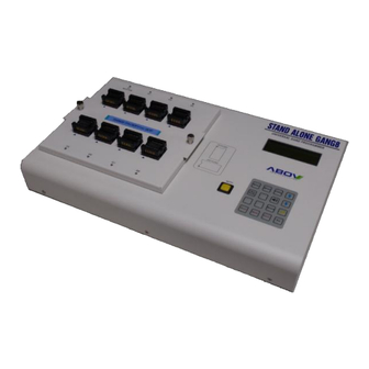
- Page 5 Figure 1.3 StandAlone PGMplus (Single Writer) ..................13 Figure 1.4 StandAlone Gang8 (for Mass Production) ................13 Figure 2.1 Block Diagram ........................14 Figure 3.1 MC96FM204 20SOP/TSSOP Pin Assignment............... 15 Figure 3.2 MC96FM204 16SOP/TSSOP Pin Assignment............... 16 Figure 3.3 MC96FM214 16SOP/TSSOP Pin Assignment............... 16 Figure 4.1 20-Pin SOP Package ......................
- Page 6 MC96FM204/FM214 Figure 11.6 8-Bit Timer/Counter 0 Example .................... 88 Figure 11.7 8-Bit Timer 0 Block Diagram ....................89 Figure 11.8 16-Bit Timer/Counter Mode for Timer 1 ................93 Figure 11.9 16-Bit Timer/Counter 1 Example ..................93 Figure 11.10 16-Bit Capture Mode for Timer 1 ..................94 Figure 11.11 Input Capture Mode Operation for Timer 1 ................
- Page 7 Figure 15.1 Flash Program ROM Structure ..................151 Figure 15.2 Flow of Protection for Invalid Erase/Write ................162 List of Tables Table 1-1 Ordering Information of MC96FM204/FM214 ................. 11 Table 5-1 Normal pin description ......................21 Table 7-1 Absolute Maximum Ratings ....................25 Table 7-2 Recommended Operating Conditions ..................
- Page 8 MC96FM204/FM214 Table 12-1 Peripheral Operation during Power Down Mode ..............129 Table 12-2 Power Down Operation Register Map ................133 Table 13-1 Reset State ......................... 134 Table 13-2 Boot Process Description....................137 Table 13-3 Reset Operation Register Map ................... 141 Table 15-1 Flash Memory Register Map ....................
-
Page 9: Overview
1. Overview 1.1 Description The MC96FM204/FM214 are advanced CMOS 8-bit microcontroller with 4k bytes of FLASH. This is powerful microcontroller which provides a highly flexible and cost effective solution to many embedded control applications. This provides the following features : 4k bytes of FLASH, 256 bytes of IRAM, general purpose I/O, basic interval... -
Page 10: Features
MC96FM204/FM214 1.2 Features • CPU • Low Voltage Reset - 8 Bit CISC Core (8051 Compatible) - 14 level detect (1.60V/ 2.00V/ 2.10V/ 2.20V/ 2.32V/ 2.44V/2.59V/ 2.75V/ 2.93V/ 3.14V/ • ROM (FLASH) Capacity 3.38V/ 3.67V/ 4.00V/ 4.40V) - 4k Bytes •... -
Page 11: Ordering Information
MC96FM204/FM214 1.3 Ordering Information Table 1-1 Ordering Information of MC96FM204/FM214 Device name ROM size IRAM size XRAM size Package MC96FM204D 20 SOP MC96FM204R 20 TSSOP MC96FM204M 16 SOP – 4k bytes FLASH 256 bytes MC96FM204H 16 TSSOP MC96FM214M 16 SOP... -
Page 12: Development Tools
1.4.1 Compiler We do not provide the compiler. Please contact third parties. The core of MC96FM204/FM214 is Mentor 8051. And, device ROM size is smaller than 64k bytes. Developer can use all kinds of third party’s standard 8051 compiler. 1.4.2 OCD emulator and debugger The OCD (On Chip Debug) emulator supports ABOV Semiconductor’s 8051 series MCU emulation. -
Page 13: Figure 1.2 Pgmplususb (Single Writer)
MC96FM204/FM214 1.4.3 Programmer Single programmer: PGMplus USB: It programs MCU device directly. Figure 1.2 PGMplusUSB (Single Writer) StandAlone PGMplus: It programs MCU device directly. Figure 1.3 StandAlone PGMplus (Single Writer) OCD emulator: It can write code in MCU device too, because OCD debugging supports ISP (In System Programming). -
Page 14: Block Diagram
MC96FM204/FM214 2. Block Diagram DSDA DSCL Low Voltage AN0-AN3/P04-P07 8 – Bit Indicator AN4-AN7/P10-P13 A/D Converter On-Chip Debug AVSS Buzzer BUZO/P12 M8051 Core OP0P/P07 OP0N/P06 OP AMP 0/1 4k Bytes Flash MOSI/P04 OP0OUT/P05 MISO/P03 OP1IN/P04 SCK/P02 256 Bytes IRAM SS/P01 8 –... -
Page 15: Pin Assignment
P03/XIN/MISO P04/AN0/MOSI/OP1IN P02/XOUT/SCK P05/AN1/OP0OUT P01/RESETB/SS/EC1 P06/AN2/OP0N P00/T1O/PWM1O/EINT11 P07/AN3/OP0P P21/DSCL AVSS P20/DSDA P10/AN4/CMP-/EINT0 P16/EC2 P11/AN5/CMP+/EINT1 P15/T2O/PWM2O/EINT12 P12/AN6/CMPO/BUZO P14/EINT3 P13/AN7/EINT2 Figure 3.1 MC96FM204 20SOP/TSSOP Pin Assignment NOTE) On On-Chip Debugging, ISP uses P2[1:0] pin as DSDA, DSCL. April 7, 2016 Ver. 1.8... -
Page 16: Figure 3.2 Mc96Fm204 16Sop/Tssop Pin Assignment
P10/AN4/CMP-/EINT0 P12/AN6/CMPO/BUZO P11/AN5/CMP+/EINT1 Figure 3.2 MC96FM204 16SOP/TSSOP Pin Assignment NOTES) 1. On On-Chip Debugging, ISP uses P2[1:0] pin as DSDA, DSCL. 2. The P13-P16 pins should be selected as a push-pull output or an input with pull-up resistor by software control when the 16-pin(with OP-AMP) package is used. -
Page 17: Package Diagram
MC96FM204/FM214 4. Package Diagram Figure 4.1 20-Pin SOP Package April 7, 2016 Ver. 1.8... -
Page 18: Figure 4.2 20-Pin Tssop Package
MC96FM204/FM214 Figure 4.2 20-Pin TSSOP Package April 7, 2016 Ver. 1.8... -
Page 19: Figure 4.3 16-Pin Sop Package
MC96FM204/FM214 Figure 4.3 16-Pin SOP Package April 7, 2016 Ver. 1.8... -
Page 20: Figure 4.4 16-Pin Tssop Package
MC96FM204/FM214 Figure 4.4 16-Pin TSSOP Package April 7, 2016 Ver. 1.8... -
Page 21: Pin Description
MC96FM204/FM214 5. Pin Description Table 5-1 Normal pin description Function @RESET Shared with Name The low nibble of port 0 is a bit-programmable I/O port T1O/PWM1O/EINT11 Input which can be configured as a schmitt-trigger input, a RESETB/SS/EC1 push-pull output, or an open-drain output. - Page 22 MC96FM204/FM214 Table 5-1 Normal pin description (Continued) Function @RESET Shared with Name A/D converter analog input channels Input P04/MOSI/OP1IN P05/OP0OUT P06/OP0N P07/OP0P P10/CMP-/EINT0 P11/CMP+/EINT1 P12/CMPO/BUZO P13/EINT2 Output (NOTE4,5) DSDA On chip debugger data input/output Input (NOTE4, 5) DSCL On chip debugger clock input...
-
Page 23: Port Structures
MC96FM204/FM214 6. Port Structures 6.1 General Purpose I/O Port Level Shift (1.8V to ExtVDD) Level Shift (ExtVDD to 1.8V) PULL-UP REGISTER OPEN DRAIN REGISTER DATA REGISTER SUB-FUNC DATA OUTPUT SUB-FUNC ENABLE SUB-FUNC DIRECTION DIRECTION REGISTER CMOS or Schmitt Level Input... -
Page 24: External Interrupt I/O Port
MC96FM204/FM214 6.2 External Interrupt I/O Port Level Shift (1.8V to ExtVDD) Level Shift (ExtVDD to 1.8V) PULL-UP REGISTER OPEN DRAIN REGISTER DATA REGISTER SUB-FUNC DATA OUTPUT SUB-FUNC ENABLE SUB-FUNC DIRECTION DIRECTION REGISTER EXTERNAL INTERRUPT POLARITY REG. INTERRUPT ENABLE FLAG CLEAR... -
Page 25: Electrical Characteristics
MC96FM204/FM214 7. Electrical Characteristics 7.1 Absolute Maximum Ratings Table 7-1 Absolute Maximum Ratings Parameter Symbol Rating Unit NOTE -0.3 – +6.0 – Supply Voltage -0.3 – VDD+0.3 Voltage on any pin with respect to VSS -0.3 – VDD+0.3 Maximum current output sourced by (I... -
Page 26: A/D Converter Characteristics
MC96FM204/FM214 7.3 A/D Converter Characteristics Table 7-3 A/D Converter Characteristics = -40°C – +85°C, VDD= 1.8V – 5.5V, VSS= 0V) Parameter Symbol Conditions Unit – – – – Resolution VDD= 2.7V – 5.5V – – – Total Accuracy ±3 fx= 8MHz –... -
Page 27: Low Voltage Reset And Low Voltage Indicator Characteristics
MC96FM204/FM214 7.5 Low Voltage Reset and Low Voltage Indicator Characteristics Table 7-5 LVR and LVI Characteristics = -40°C – +85°C, VDD= 1.8V – 5.5V, VSS= 0V) Parameter Symbol Conditions Unit – 1.60 1.75 1.85 2.00 2.15 1.95 2.10 2.25 2.05 2.20... -
Page 28: Analog Comparator Characteristics
MC96FM204/FM214 7.6 Analog Comparator Characteristics Table 7-6 Analog Comparator Characteristics = -40°C – +85°C, VDD= 1.8V – 5.5V, VSS= 0V) Parameter Symbol Conditions Unit – – Input Offset Voltage ±50 – – Response Time =3.0V, V =1/2V – △V Hysteresis –... -
Page 29: High Frequency Internal Rc Oscillator Characteristics
MC96FM204/FM214 7.8 High Frequency Internal RC Oscillator Characteristics Table 7-8 High Frequency Internal RC Oscillator Characteristics = -40°C – +85°C, VDD= 1.8V – 5.5V, VSS= 0V) Parameter Symbol Conditions Unit – Frequency – – HFIRC = 0°C – +70°C –... -
Page 30: Dc Characteristics
MC96FM204/FM214 7.11 DC Characteristics Table 7-11 DC Characteristics = -40°C – +85°C, VDD= 1.8V – 5.5V, VSS= 0V, f = 8MHz) Parameter Symbol Conditions Unit P00 – P03, P1, RESETB – 0.8VDD Input High Voltage All input pins except VIH1 –... -
Page 31: Ac Characteristics
MC96FM204/FM214 7.12 AC Characteristics Table 7-12 AC Characteristics = -40°C – +85°C, VDD= 1.8V – 5.5V) Parameter Symbol Conditions Unit – – μS RESETB input low width = 5 V Interrupt Input High, – – All interrupts, V = 5 V... -
Page 32: Spi Characteristics
MC96FM204/FM214 7.13 SPI Characteristics Table 7-13 SPI Characteristics = -40°C – +85°C, VDD= 1.8V – 5.5V) Parameter Symbol Conditions Unit – – Output Clock Pulse Period Internal SCK source – – Input Clock Pulse Period External SCK source Output Clock High, –... -
Page 33: Data Retention Voltage In Stop Mode
MC96FM204/FM214 7.14 Data Retention Voltage in Stop Mode Table 7-14 Data Retention Voltage in Stop ModeR = -40°C – +85°C, VDD= 1.8V – 5.5V) Parameter Symbol Conditions Unit – – Data retention supply voltage DDDR VDDR= 1.8V, – – μA... -
Page 34: Internal Flash Rom Characteristics
MC96FM204/FM214 7.15 Internal Flash Rom Characteristics Table 7-15 Internal flash Rom Characteristics = -40°C – +85°C, VDD= 1.8V – 5.5V, VSS= 0V) Parameter Symbol Condition Unit – – Sector Write Time – – Sector Erase Time – – Hard-Lock Time –... -
Page 35: Main Clock Oscillator Characteristics
MC96FM204/FM214 7.17 Main Clock Oscillator Characteristics Table 7-17 Main Clock Oscillator Characteristics = -40°C – +85°C, VDD= 1.8V – 5.5V) Oscillator Parameter Condition Unit 1.8V – 5.5V – Crystal Main oscillation frequency 2.7V – 5.5V – 10.0 3.0V – 5.5V –... -
Page 36: Main Oscillation Stabilization Characteristics
MC96FM204/FM214 7.18 Main Oscillation Stabilization Characteristics Table 7-18 Main Oscillation Stabilization Characteristics = -40°C – +85°C, VDD= 1.8V – 5.5V) Oscillator Parameter Unit fx > 1MHz – – Crystal Oscillation stabilization occurs when VDD is equal to the minimum oscillator voltage –... -
Page 37: Recommended Circuit And Layout
MC96FM204/FM214 7.20 Recommended Circuit and Layout This 0.1uF capacitor should be within 1cm from the VDD pin of MCU on the VDD VCC PCB layout. DC Power 0.1uF 0.1uF The MCU power line (VDD and VSS) should be separated from the high-... -
Page 38: Recommended Circuit And Layout With Smps Power
MC96FM204/FM214 7.21 Recommended Circuit and Layout with SMPS Power SMPS Side MCU Side SMPS 1. The C1 capacitor is to flatten out the voltage of the SMPS power, VCC. √ Recommended C1: 470uF/25V more. 2. The R1 and C2 are the RC filter for VDD and suppress the ripple of VCC. -
Page 39: Typical Characteristics
MC96FM204/FM214 7.22 Typical Characteristics These graphs and tables provided in this section are only for design guidance and are not tested or guaranteed. In graphs or tables some data are out of specified operating range (e.g. out of specified VDD range). This is only for information and devices are guaranteed to operate properly only within the specified range. -
Page 40: Figure 7.13 Run (Idd1, Lfirc=250Khz) Current
MC96FM204/FM214 120.00 100.00 80.00 -40℃ 60.00 +25℃ +85℃ 40.00 20.00 0.00 2.7V 3.0V 3.3V Figure 7.13 RUN (IDD1, LFIRC=250kHz) Current 1.60 1.40 1.20 1.00 -40℃ 0.80 +25℃ 0.60 +85℃ 0.40 0.20 0.00 2.7V 3.0V 3.3V 4.5V 5.0V 5.5V Figure 7.14 IDLE (IDD2, XIN=8MHz) Current... -
Page 41: Figure 7.15 Idle (Idd2, Hfirc =8Mhz) Current
MC96FM204/FM214 0.68 0.66 0.64 -40℃ 0.62 +25℃ +85℃ 0.60 0.58 0.56 4.5V 5.0V 5.5V Figure 7.15 IDLE (IDD2, HFIRC =8MHz) Current 70.00 60.00 50.00 40.00 -40℃ +25℃ 30.00 +85℃ 20.00 10.00 0.00 2.7V 3.0V 3.3V Figure 7.16 IDLE (IDD2, LFIRC=250kHz) Current... -
Page 42: Figure 7.17 Stop (Idd5, Xin=8Mhz) Current
MC96FM204/FM214 2.50 2.00 1.50 -40℃ +25℃ 1.00 +85℃ 0.50 0.00 2.7V 3.0V 3.3V 4.5V 5.0V 5.5V Figure 7.17 STOP (IDD5, XIN=8MHz) Current April 7, 2016 Ver. 1.8... -
Page 43: Memory
DPTR register. MC96FM204/FM214 provides on-chip 4k bytes of the ISP type flash program memory, which can be read and written to. Internal data memory (IRAM) is 256 bytes and it includes the stack area. -
Page 44: Figure 8.1 Program Memory
MC96FM204/FM214 FFFFH 0FFFH 4k Bytes 0000H Figure 8.1 Program Memory 4k Bytes Including Interrupt Vector Region April 7, 2016 Ver. 1.8... -
Page 45: Data Memory
MC96FM204/FM214 8.2 Data Memory Figure 8-2 shows the internal data memory space available. Upper 128 Bytes Special Function Registers Internal RAM 128 Bytes (Indirect Addressing) (Direct Addressing) Lower 128 Bytes Internal RAM (Direct or Indirect Addressing) Figure 8.2 Data Memory Map The internal data memory space is divided into three blocks, which are generally referred to as the lower 128 bytes, upper 128 bytes, and SFR space. -
Page 46: Figure 8.3 Lower 128 Bytes Ram
MC96FM204/FM214 7F 7E 7D 7C 7B 7A 79 78 77 76 75 74 73 72 71 70 6F 6E 6D 6C 6B 6A 69 68 67 66 65 64 63 62 61 60 5F 5E 5D 5C 5B 5A 59 58... -
Page 47: Sfr Map
MC96FM204/FM214 8.3 SFR Map 8.3.1 SFR Map Summary Reserved Table 8-1 SFR Map Summary M8051 compatible 00H/8H 01H/9H 02H/0AH 03H/0BH 04H/0CH 05H/0DH 06H/0EH 07H/0FH – – 0F8H FSADRH FSADRM FSADRL FIDR FMCR – – – – – – – 0F0H –... -
Page 48: Table 8-2 Sfr Map
MC96FM204/FM214 8.3.2 SFR Map Table 8-2 SFR Map @Reset Address Function Symbol P0 Data Register Stack Pointer Data Pointer Register Low Data Pointer Register High Data Pointer Register Low 1 DPL1 Data Pointer Register High 1 DPH1 – – –... - Page 49 MC96FM204/FM214 Table 8-2 SFR Map (Continued) @Reset Address Function Symbol – – External Interrupt Flag Register EIFLAG – – – – – – P2 Pull-up Resistor Selection Register P2PU – – – – Extended Operation Register – – – Reserved...
- Page 50 MC96FM204/FM214 Table 8-2 SFR Map (Continued) @Reset Address Function Symbol – – – SPI Status Register SPISR – – – Reserved – Timer 2 Control Low Register T2CRL – – – – Timer 2 Control High Register T2CRH Timer 2 A Data Low Register...
- Page 51 MC96FM204/FM214 Table 8-2 SFR Map (Continued) @Reset Address Function Symbol Accumulator Register – – Low Voltage Indicator Control Register LVICR – – – Reserved – – – Reserved – – – Reserved – – – Reserved – – – Reserved –...
- Page 52 MC96FM204/FM214 8.3.3 Compiler Compatible SFR ACC (Accumulator Register) : E0H Initial value : 00H Accumulator B (B Register) : F0H Initial value : 00H B Register SP (Stack Pointer) : 81H Initial value : 07H Stack Pointer DPL (Data Pointer Register Low) : 82H...
- Page 53 MC96FM204/FM214 DPL1 (Data Pointer Register Low 1) : 84H DPL1 Initial value : 00H DPL1 Data Pointer Low 1 DPH1 (Data Pointer Register High 1) : 85H DPH1 Initial value : 00H DPH1 Data Pointer High 1 PSW (Program Status Word Register) : D0H...
-
Page 54: I/O Ports
9. I/O Ports 9.1 I/O Ports The MC96FM204/FM214 has three groups of I/O ports (P0 ~ P2). Each port can be easily configured by software as I/O pin, internal pull up and open-drain pin to meet various system configurations and design requirements. -
Page 55: Table 9-1 Port Register Map
MC96FM204/FM214 9.2.7 Register Map Table 9-1 Port Register Map Name Address Default Description P0 Data Register P0IO P0 Direction Register P0OD P0 Open-drain Selection Register P0PU P0 Pull-up Resistor Selection Register P0DB P0 Debounce Enable Register P0FSRH Port 0 Function Selection High Register... -
Page 56: P0 Port
MC96FM204/FM214 9.3 P0 Port 9.3.1 P0 Port Description P0 is 8-bit I/O port. P0 control registers consist of P0 data register (P0), P0 direction register (P0IO), debounce enable register (P0DB), P0 pull-up resistor selection register (P0PU), and P0 open-drain selection register (P0OD). - Page 57 MC96FM204/FM214 P0OD (P0 Open-drain Selection Register) : 92H P07OD P06OD P05OD P04OD P03OD P02OD P01OD P00OD Initial value : 00H P0OD[7:0] Configure Open-drain of P0 Port Push-pull output Open-drain output P0DB (P0 Debounce Enable Register): A6H – – – –...
- Page 58 MC96FM204/FM214 P0FSRH (Port 0 Function Selection High Register) : EDH PFSRH07 PFSRH06 PFSRH05 PFSRH04 PFSRH03 PFSRH02 PFSRH01 PFSRH00 Initial value : 00H PFSRH0[7:6] P07 Function select PFSRH07 PFSRH06 Description I/O Port OP0P Function AN3 Function Not used PFSRH0[5:4] P06 Function select...
- Page 59 MC96FM204/FM214 P0FSRL (Port 0 Function Selection Low Register) : ECH – – – PFSRL04 PFSRL03 PFSRL02 PFSRL01 PFSRL00 – – – Initial value : 00H PFSRL0[4:3] P03 Function select PFSRL04 PFSRL03 Description I/O Port MISO Function XIN for Oscillator Not used...
-
Page 60: P1 Port
MC96FM204/FM214 9.4 P1 Port 9.4.1 P1 Port Description P1 is 7-bit I/O port. P1 control registers consist of P1 data register (P1), P1 direction register (P1IO), debounce enable register (P1DB), P1 pull-up resistor selection register (P1PU), and P1 open-drain selection register (P1OD) . - Page 61 MC96FM204/FM214 P1PU (P1 Pull-up Resistor Selection Register) : 96H – P16PU P15PU P14PU P13PU P12PU P11PU P10PU – Initial value : 00H P1PU[6:0] Configure Pull-up Resistor of P1 Port Disable Enable P1OD (P1 Open-drain Selection Register) : 95H – P16OD...
- Page 62 MC96FM204/FM214 P1FSR (Port 1 Function Selection Register) : EEH PFSR17 PFSR16 PFSR15 PFSR14 PFSR13 PFSR12 PFSR11 PFSR10 Initial value : 00H PFSRH17 P15 Function select I/O Port (EINT12 function possible when input) T2O/PWM2O Function PFSRH16 P13 Function select I/O Port (EINT3 function possible when input)
-
Page 63: P2 Port
MC96FM204/FM214 9.5 P2 Port 9.5.1 P2 Port Description P2 is 2-bit I/O port. P2 control registers consist of P2 data register (P2), P2 direction register (P2IO), P2 pull-up resistor selection register (P2PU) and P2 open-drain selection register (P2OD). 9.5.2 Register description for P2 P2 (P2 Data Register) : 90H –... -
Page 64: Interrupt Controller
10. Interrupt Controller 10.1 Overview The MC96FM204/FM214 supports up to 14 interrupt sources. The interrupts have separate enable register bits associated with them, allowing software control. They can also have four levels of priority assigned to them. The non-maskable interrupt source is always enabled with a higher priority than any other interrupt source, and is not controllable by software. -
Page 65: External Interrupt
MC96FM204/FM214 10.2 External Interrupt The external interrupt on INT0 – INT4 and INT5 pins receive various interrupt request depending on the external interrupt polarity 0 register (EIPOL0) and external interrupt polarity 1 register (EIPOL1) as shown in Figure 10.1. Also each external interrupt source has enable/disable bits. The External interrupt flag register (EIFLAG) provides the status of external interrupts. -
Page 66: Block Diagram
MC96FM204/FM214 10.3 Block Diagram EIPOL0/1 EIFLAG.0 FLAG0 EINT0 Priority High EIFLAG.1 FLAG1 EINT1 EIFLAG.2 FLAG2 EINT2 EIFLAG.3 FLAG3 EINT3 EIFLAG.4 FLAG11 EINT11 EIFLAG.5 FLAG12 EINT12 ADCIFR ACIFR Comparator Level0 Level1 SPIIFR Level2 Level3 Release Stop/Sleep T0IFR Timer 0 T1IFR Timer 1... -
Page 67: Interrupt Vector Table
MC96FM204/FM214 10.4 Interrupt Vector Table The interrupt controller supports 24 interrupt sources as shown in the Table 10-2. When interrupt is served, long call instruction (LCALL) is executed and program counter jumps to the vector address. All interrupt requests have their own priority order. -
Page 68: Figure 10.3 Interrupt Vector Address Table
MC96FM204/FM214 IE.EA Flag 0 Program Counter low Byte SP SP + 1 M(SP) (PCL) Saves PC value in order to continue process again after executing ISR Program Counter high Byte SP SP + 1 M(SP) (PCH) -
Page 69: Effective Timing After Controlling Interrupt Bit
MC96FM204/FM214 10.6 Effective Timing after Controlling Interrupt Bit Case a) Control Interrupt Enable Register (IE, IE1, IE2, IE3) Interrupt Enable Register command After executing IE set/clear, enable register is effective. Next Instruction Next Instruction Figure 10.4 Effective Timing of Interrupt Enable Register... -
Page 70: Multi Interrupt
MC96FM204/FM214 10.7 Multi Interrupt If two requests of different priority levels are received simultaneously, the request of higher priority level is served first. If more than one interrupt request are received, the interrupt polling sequence determines which request is served first by hardware. However, for special features, multi-interrupt processing can be executed by software. -
Page 71: Interrupt Enable Accept Timing
MC96FM204/FM214 10.8 Interrupt Enable Accept Timing Max. 4 Machine Cycle 4 Machine Cycle System Clock Interrupt goes Active Interrupt Interrupt Processing Latched Interrupt Routine : LCALL & LJMP Figure 10.7 Interrupt Response Timing Diagram 10.9 Interrupt Service Routine Address Basic Interval Timer... -
Page 72: Interrupt Timing
MC96FM204/FM214 10.11 Interrupt Timing Interrupt sampled here CLP2 CLP1 CLP2 C1P1 C1P2 C2P1 C2P2 SCLK INT_SRC INTR_ACK LAST_CYC INTR_LCALL 8-Bit interrupt Vector INT_VEC {8’h00, INT_VEC} PROGA Figure 10.10 Timing Chart of Interrupt Acceptance and Interrupt Return Instruction Interrupt sources are sampled at the last cycle of a command. If an interrupt source is detected the lower 8-bit of interrupt vector (INT_VEC) is decided. - Page 73 MC96FM204/FM214 10.12.3 External Interrupt Flag Register (EIFLAG) The external interrupt flag register is set to ‘1’ when the external interrupt generating condition is satisfied. The flag is cleared when the interrupt service routine is executed. Alternatively, the flag can be cleared by writing a ‘0’...
-
Page 74: Interrupt Register Description
MC96FM204/FM214 10.12.5 Register Map Table 10-3 Interrupt Register Map Name Address Default Description Interrupt Enable Register Interrupt Enable Register 1 Interrupt Enable Register 2 Interrupt Enable Register 3 Interrupt Priority Register Interrupt Priority Register 1 EIFLAG External Interrupt Flag Register... - Page 75 MC96FM204/FM214 10.13.1 Register Description for Interrupt IE (Interrupt Enable Register) : A8H – INT5E INT4E INT3E INT2E INT1E INT0E – Initial value : 00H Enable or Disable All Interrupt bits All Interrupt disable All Interrupt enable INT5E Enable or Disable External Interrupt 12...
- Page 76 MC96FM204/FM214 IE2 (Interrupt Enable Register 2) : AAH – – – – – INT16E INT13E INT12E – – – – – Initial value : 00H INT16E Enable or Disable Timer 2 Interrupt Disable Enable INT13E Enable or Disable Timer 1 Interrupt...
- Page 77 MC96FM204/FM214 IP (Interrupt Priority Register) : B8H – – – – Initial value : 00H IP1 (Interrupt Priority Register 1) : F8H – – IP15 IP14 IP13 IP12 IP11 IP10 – – Initial value : 00H IP[5:0], IP1[5:0] Select Interrupt Group Priority...
- Page 78 MC96FM204/FM214 EIFLAG (External Interrupt Flag Register) : A0H – – FLAG12 FLAG11 FLAG3 FLAG2 FLAG1 FLAG0 – – Initial value : 00H When an external interrupt is occurred, the flag becomes ‘1’. EIFLAG0[5:0] The flag is cleared by writing ‘0’ to the bit or automatically...
-
Page 79: Peripheral Hardware
MC96FM204/FM214 11. Peripheral Hardware 11.1 Clock Generator 11.1.1 Overview As shown in Figure 11.1, the clock generator produces the basic clock pulses which provide the system clock to be supplied to the CPU and the peripheral hardware. It contains main frequency clock oscillator. The main clock operation can be easily obtained by attaching a crystal between the XIN and XOUT pin, respectively. -
Page 80: Table 11-1 Clock Generator Register Map
MC96FM204/FM214 11.1.3 Register Map Table 11-1 Clock Generator Register Map Name Address Default Description SCCR System and Clock Control Register OSCCR Oscillator Control Register 11.1.4 Clock Generator Register Description The clock generator register uses clock control for system operation. The clock generation consists of System and clock control register and oscillator control register. - Page 81 MC96FM204/FM214 OSCCR (Oscillator Control Register) : C8H – – – LFIRCE IRCS1 IRCS0 HFIRCE XCLKE – – – Initial value : 20H LFIRCE Control the operation of the low frequency internal RC oscillator Enable operation of LF INT-RC OSC Disable operation of LF INT-RC OSC...
-
Page 82: Basic Interval Timer
11.2 Basic Interval Timer 11.2.1 Overview The MC96FM204/FM214 has one 8-bit basic interval timer that is free-run and can’t stop. Block diagram is shown in Figure 11.2. In addition, the basic interval timer generates the time base for watchdog timer counting. It also provides a basic interval timer interrupt (BITIFR). -
Page 83: Table 11-2 Basic Interval Timer Register Map
MC96FM204/FM214 11.2.3 Register Map Table 11-2 Basic Interval Timer Register Map Name Address Default Description BITCNT Basic Interval Timer Counter Register BITCR Basic Interval Timer Control Register 11.2.4 Basic Interval Timer Register Description The basic interval timer register consists of basic interval timer counter register (BITCNT) and basic interval timer control register (BITCR). -
Page 84: Watch Dog Timer
MC96FM204/FM214 11.3 Watch Dog Timer 11.3.1 Overview The watchdog timer rapidly detects the CPU malfunction such as endless looping caused by noise or something like that, and resumes the CPU to the normal state. The watchdog timer signal for malfunction detection can be used as either a CPU reset or an interrupt request. -
Page 85: Figure 11.4 Watch Dog Timer Block Diagram
MC96FM204/FM214 11.3.3 Block Diagram clear WDT Clock To RESET WDTCNT Circuit WDTEN To interrupt WDTIFR block clear WDTDR INT_ACK WDTCL WDTRSON WDTCR Figure 11.4 Watch Dog Timer Block Diagram 11.3.4 Register Map Table 11-3 Watch Dog Timer Register Map Name... - Page 86 MC96FM204/FM214 11.3.6 Register Description for Watch Dog Timer WDTCNT (Watch Dog Timer Counter Register: Read Case) : 8EH WDTCNT 7 WDTCNT 6 WDTCNT 5 WDTCNT 4 WDTCNT3 WDTCNT 2 WDTCNT 1 WDTCNT 0 Initial value : 00H WDTCNT[7:0] WDT Counter...
-
Page 87: Timer 0
MC96FM204/FM214 11.4 Timer 0 11.4.1 Overview The 8-bit timer 0 consists of multiplexer, timer 0 counter register, timer 0 data register and timer 0 control register (T0CNT, T0DR, T0CR). 8-bit timer/counter mode The timer/counter 0 can be clocked by an internal clock source. The clock source is selected by clock selection logic which is controlled by the clock selection bits (T0CK[2:0]). -
Page 88: Figure 11.6 8-Bit Timer/Counter 0 Example
MC96FM204/FM214 Match with T0DR T0CNT Value Count Pulse Period Up-count TIME Interrupt Period x (n+1) Timer 0 (T0IFR) Occur Occur Occur Interrupt Interrupt Interrupt Interrupt Figure 11.6 8-Bit Timer/Counter 0 Example April 7, 2016 Ver. 1.8... -
Page 89: Figure 11.7 8-Bit Timer 0 Block Diagram
MC96FM204/FM214 11.4.3 Block Diagram fx/1 fx/4 fx/16 8-bit Counter T0CC Clear fx/64 T0CNT (8Bit) Match signal fx/256 fx/1024 Match T0EN T0IFR To interrupt block fx/4096 Comparator Clear T0DR (8Bit) INT_ACK T0CK[2:0] 8-bit Data Register Figure 11.7 8-Bit Timer 0 Block Diagram... -
Page 90: Table 11-4 Timer 0 Register Map
MC96FM204/FM214 11.4.4 Register Map Table 11-4 Timer 0 Register Map Name Address Default Description T0CNT Timer 0 Counter Register T0DR Timer 0 Data Register T0CR Timer 0 Control Register 11.4.4.1 Timer/Counter 0 Register Description The timer/counter 0 register consists of timer 0 counter register (T0CNT), timer 0 data register (T0DR), and timer 0 control register (T0CR). - Page 91 MC96FM204/FM214 T0CR (Timer 0 Control Register) : B2H – – T0EN T0IFR T0CK2 T0CK1 T0CK0 T0CC – – Initial value : 00H T0EN Control Timer 0 Timer 0 disable Timer 0 enable When T0 Interrupt occurs, this bit becomes ‘1’. For clearing bit, write ‘0’...
-
Page 92: Timer 1
MC96FM204/FM214 11.5 Timer 1 11.5.1.1 Overview The 16-bit timer 1 consists of multiplexer, timer 1 A data register high/low, timer 1 B data register high/low and timer 1 control register high/low (T1ADRH, T1ADRL, T1BDRH, T1BDRL, T1CRH, T1CRL). It has four operating modes:... -
Page 93: Figure 11.8 16-Bit Timer/Counter Mode For Timer 1
MC96FM204/FM214 ADDRESS:BBH – – – – T1EN T1MS1 T1MS0 T1CC T1CRH INITIAL VALUE : 0000_0000B – – – – ADDRESS:BAH – T1CK2 T1CK1 T1CK0 T1IFR T1POL T1ECE T1CNTR T1CRL INITIAL VALUE : 0000_0000B – 16-bit A Data Register T1ADRH/T1ADRL A Match... -
Page 94: Figure 11.10 16-Bit Capture Mode For Timer 1
MC96FM204/FM214 11.5.3 16-Bit Capture Mode The 16-bit timer 1 capture mode is set by T1MS[1:0] as ‘01’. The clock source can use the internal/external clock. Basically, it has the same function as the 16-bit timer/counter mode and the interrupt occurs when T1CNTH/L is equal to T1ADRH/L. -
Page 95: Figure 11.11 Input Capture Mode Operation For Timer 1
MC96FM204/FM214 T1BDRH/L Load T1CNTH/L Value Count Pulse Period Up-count TIME Ext. EINT11 PIN Interrupt Request (FLAG11) Interrupt Interval Period Figure 11.11 Input Capture Mode Operation for Timer 1 FFFF FFFF T1CNTH/L Interrupt Request (T1IFR) Ext. EINT11 PIN Interrupt Request (FLAG11) -
Page 96: Figure 11.13 16-Bit Ppg Mode For Timer 1
MC96FM204/FM214 11.5.4 16-Bit PPG Mode The timer 1 has a PPG (Programmable Pulse Generation) function. In PPG mode, T1O/PWM1O pin outputs up to 16-bit resolution PWM output. This pin should be configured as a PWM output by setting PFSRL00 to ‘1’ . -
Page 97: Figure 11.14 16-Bit Ppg Mode Timming Chart For Timer 1
MC96FM204/FM214 Repeat Mode(T1MS = 11b) and "Start High"(T1POL = 0b). Clear and Start Set T1EN Timer 1 clock Counter T1ADRH/L T1 Interrupt 1. T1BDRH/L(5) < T1ADRH/L PWM1O B Match A Match 2. T1BDRH/L >= T1ADRH/L PWM1O A Match 3. T1BDRH/L = "0000H"... -
Page 98: Figure 11.15 16-Bit Timer 1 Block Diagram
MC96FM204/FM214 11.5.5 Block Diagram 16-bit A Data Register T1ADRH/T1ADRL A Match Reload T1CC T1EN T1CK[2:0] T1ECE INT_ACK Buffer Register A Clear Edge A Match To interrupt Detector T1IFR block T1EN fx/1 Comparator fx/2 A Match Clear fx/4 16-bit Counter T1CC... - Page 99 MC96FM204/FM214 11.5.6.2 Register Description for Timer/Counter 1 T1ADRH (Timer 1 A data High Register) : BDH T1ADRH7 T1ADRH6 T1ADRH5 T1ADRH4 T1ADRH3 T1ADRH2 T1ADRH1 T1ADRH0 Initial value : FFH T1ADRH[7:0] T1 A Data High Byte T1ADRL (Timer 1 A Data Low Register) : BCH...
- Page 100 MC96FM204/FM214 T1CRH (Timer 1 Control High Register) : BBH – – – – T1EN T1MS1 T1MS0 T1CC – – – – Initial value : 00H T1EN Control Timer 1 Timer 1 disable Timer 1 enable (Counter clear and start) T1MS[1:0]...
- Page 101 MC96FM204/FM214 T1CRL (Timer 1 Control Low Register) : BAH – T1CK2 T1CK1 T1CK0 T1IFR T1POL T1ECE T1CNTR – Initial value : 00H T1CK[2:0] Select Timer 1 clock source. fx is main system clock frequency T1CK2 T1CK1 T1CK0 Description fx/2048 fx/512...
-
Page 102: Timer 2
MC96FM204/FM214 11.6 Timer 2 11.6.1 Overview The 16-bit timer 2 consists of multiplexer, timer 2 A data register high/low, timer 2 B data register high/low and timer 2 control register high/low (T2ADRH, T2ADRL, T2BDRH, T2BDRL, T2CRH, T2CRL). It has four operating modes:... -
Page 103: Figure 11.16 16-Bit Timer/Counter Mode For Timer 2
MC96FM204/FM214 ADDRESS:C3H – – – – T2EN T2MS1 T2MS0 T2CC T2CRH INITIAL VALUE : 0000_0000B – – – – ADDRESS:C2H – T2CK2 T2CK1 T2CK0 T2IFR T2POL T2ECE T2CNTR T2CRL INITIAL VALUE : 0000_0000B – 16-bit A Data Register T2ADRH/T2ADRL A Match... -
Page 104: Figure 11.18 16-Bit Capture Mode For Timer 2
MC96FM204/FM214 11.6.3 16-Bit Capture Mode The timer 2 capture mode is set by T2MS[1:0] as ‘01’. The clock source can use the internal/external clock. Basically, it has the same function as the 16-bit timer/counter mode and the interrupt occurs when T2CNTH/L is equal to T2ADRH/L. -
Page 105: Figure 11.19 Input Capture Mode Operation For Timer 2
MC96FM204/FM214 T2BDRH/L Load T2CNTH/L Value Count Pulse Period Up-count TIME Ext. EINT12 PIN Interrupt Request (FLAG12) Interrupt Interval Period Figure 11.19 Input Capture Mode Operation for Timer 2 FFFF FFFF T2CNTH/L Interrupt Request (T2IFR) Ext. EINT12 PIN Interrupt Request (FLAG12) -
Page 106: Figure 11.21 16-Bit Ppg Mode For Timer 2
MC96FM204/FM214 11.6.4 16-Bit PPG Mode The timer 2 has a PPG (Programmable Pulse Generation) function. In PPG mode, T2O/PWM2O pin outputs up to 16-bit resolution PWM output. This pin should be configured as a PWM output by setting PFSR17 to ‘1’ . -
Page 107: Figure 11.22 16-Bit Ppg Mode Timming Chart For Timer 2
MC96FM204/FM214 Repeat Mode(T2MS = 11b) and "Start High"(T2POL = 0b). Clear and Start Set T2EN Timer 2 clock Counter T2ADRH/L T2 Interrupt 1. T2BDRH/L(5) < T2ADRH/L PWM2O B Match A Match 2. T2BDRH/L >= T2ADRH/L PWM2O A Match 3. T2BDRH/L = "0000H"... -
Page 108: Figure 11.23 16-Bit Timer 2 Block Diagram
MC96FM204/FM214 11.6.5 Block Diagram 16-bit A Data Register T2ADRH/T2ADRL A Match Reload T2CC T2EN T2CK[2:0] T2ECE INT_ACK Buffer Register A Clear Edge A Match To interrupt Detector T2IFR block T2EN fx/1 Comparator fx/2 A Match Clear fx/4 16-bit Counter T2CC... - Page 109 MC96FM204/FM214 11.6.6.2 Register Description for Timer/Counter 2 T2ADRH (Timer 2 A data High Register) : C5H T2ADRH7 T2ADRH6 T2ADRH5 T2ADRH4 T2ADRH3 T2ADRH2 T2ADRH1 T2ADRH0 Initial value : FFH T2ADRH[7:0] T2 A Data High Byte T2ADRL (Timer 2 A Data Low Register) : C4H...
- Page 110 MC96FM204/FM214 T2CRH (Timer 2 Control High Register) : C3H – – – – T2EN T2MS1 T2MS0 T2CC – – – – Initial value : 00H T2EN Control Timer 2 Timer 2 disable Timer 2 enable (Counter clear and start) T2MS[1:0]...
- Page 111 MC96FM204/FM214 T2CRL (Timer 2 Control Low Register) : C2H – T2CK2 T2CK1 T2CK0 T2IFR T2POL T2ECE T2CNTR – Initial value : 00H T2CK[2:0] Select Timer 2 clock source. fx is main system clock frequency T2CK2 T2CK1 T2CK0 Description fx/2048 fx/512...
-
Page 112: Buzzer Driver
MC96FM204/FM214 11.7 Buzzer Driver 11.7.1 Overview The buzzer consists of 8 bit counter, buzzer data register (BUZDR), and buzzer control register (BUZCR). The Square Wave (61.035Hz – 125.0 kHz @8MHz) is outputted through P12/AN6/CMPO/BUZO pin. The buzzer data register (BUZDR) controls the buzzer frequency (look at the following expression). In buzzer control register (BUZCR), BUCK[1:0] selects source clock divided by prescaler. -
Page 113: Table 11-10 Buzzer Driver Register Map
MC96FM204/FM214 11.7.3 Register Map Table 11-10 Buzzer Driver Register Map Name Address Default Description BUZDR Buzzer Data Register BUZCR Buzzer Control Register 11.7.4 Buzzer Driver Register Description Buzzer driver consists of buzzer data register (BUZDR), buzzer control register (BUZCR). 11.7.5 Register Description for Buzzer Driver... -
Page 114: Spi
MC96FM204/FM214 11.8 SPI 11.8.1 Overview There is serial peripheral interface (SPI) one channel in MC96M204/FM214. The SPI allows synchronous serial data transfer between the external serial devices. It can do Full-duplex communication by 4-wire (MOSI, MISO, SCK, SS), support master/slave mode, can select serial clock (SCK) polarity, phase and whether LSB first data transfer or MSB first data transfer. - Page 115 MC96FM204/FM214 11.8.3 Data Transmit / Receive Operation User can use SPI for serial data communication by following step 1. Select SPI operation mode(master/slave, polarity, phase) by control register SPICR. 2. When the SPI is configured as a Master, it selects a Slave by SS signal (active low).
-
Page 116: Figure 11.26 Spi Transmit/Receive Timing Diagram At Cpha = 0
MC96FM204/FM214 11.8.5 SPI Timing Diagram (CPOL = 0) (CPOL = 1) MISO/MOSI (Output) MOSI/MISO (Input) SPIIFR SPI Transmit/Receive Timing Diagram at CPHA = 0 Figure 11.26 (CPOL = 0) (CPOL = 1) MISO/MOSI (Output) MOSI/MISO (Input) SPIIFR SPI Transmit/Receive Timing Diagram at CPHA = 1 Figure 11.27... -
Page 117: Table 11-11 Spi Register Map
MC96FM204/FM214 11.8.6 Register Map Table 11-11 SPI Register Map Name Address Default Description SPISR SPI Status Register SPIDR SPI Data Register SPICR SPI Control Register 11.8.7 SPI Register Description The SPI register consists of SPI control register (SPICR), SPI status register (SPISR) and SPI data register (SPIDR) 11.8.8 Register Description for SPI... - Page 118 MC96FM204/FM214 SPISR (SPI Status Register) : C0H – – – SPIIFR WCOL SS_HIGH FXCH SSENA – – – Initial value : 00H When SPI Interrupt occurs, this bit becomes ‘1’. IF SPI interrupt is SPIIFR enable, this bit is auto cleared by INT_ACK signal. And if SPI Interrupt...
- Page 119 MC96FM204/FM214 SPICR (SPI Control Register) : B5H SPIEN FLSB CPOL CPHA DSCR SCR1 SCR0 Initial value : 00H SPIEN This bit controls the SPI operation Disable SPI operation Enable SPI operation FLSB This bit selects the data transmission sequence MSB first mode...
-
Page 120: 8-Bit A/D Converter
MC96FM204/FM214 11.9 8-Bit A/D Converter 11.9.1 Overview The analog-to-digital(A/D) converter allows conversion of an analog input signal to an corresponding 8-bit digital value. The A/D module has eight analog inputs, which are multiplexer into one sample and hold. The output of the sample and hold is the input of the converter which generates the result through successive approximation. -
Page 121: Figure 11.28 8-Bit Adc Block Diagram
MC96FM204/FM214 11.9.3 Block Diagram fx/1 Reference fx/2 Voltage ADCCK AVSS fx/4 Scaler fx/8 Start STOP (Power Down) STBY CKSEL[1:0] Sample To interrupt 8-bit SAR ADCIFR block Hold Clear Clear OP0OUT AFLAG INT_ACK OP1OUT To PGA ADCDR ADSEL[3:0] block (Read only) -
Page 122: Figure 11.30 A/D Converter Operation Flow
MC96FM204/FM214 SET ADCCRH Select ADC Clock SET ADCCRL ADC enable & Select AN Input Channel. Converting START Start ADC Conversion. If Conversion is completed, AFLAG is set “1” and ADC AFLAG = 1? interrupt is occurred. After Conversion is completed, read ADCD... - Page 123 MC96FM204/FM214 11.9.5 ADC Register Description The A/D converter control High register (ADCCRH), A/D converter control low register (ADCCRL), Sample and hold timing data register (SHTDR) and A/D converter data register (ADCDR) 11.9.6 Register Description for ADC ADCDR (A/D Converter Data Register) : 9CH...
- Page 124 MC96FM204/FM214 ADCCRL (A/D Converter Counter Low Register) : B0H STBY ADST ADCIFR AFLAG ADSEL3 ADSEL2 ADSEL1 ADSEL0 Initial value : 00H STBY Control Operation of A/D (The ADC module is automatically disabled at stop mode) ADC module disable ADC module enable ADST Control Trigger Signal for A/D Conversion stop/start.
-
Page 125: Analog Comparator
MC96FM204/FM214 11.10 Analog Comparator 11.10.1 Overview The analog comparator compares the input values on the positive pin CMP+ and negative pin CMP-. When the voltage on the positive pin CMP+ is higher than the voltage on the negative pin CMP-, the analog comparator output, CMPO, is set. -
Page 126: Table 11-13 Adc Register Map
MC96FM204/FM214 11.10.3 Register Map Table 11-13 ADC Register Map Name Address Default Description ACCSR Analog Comparator Control & Status Register 11.10.4 Analog Comparator Register Description The analog comparator control and status register (ACCSR) 11.10.5 Register Description for ACCSR ACCSR (Anlaog Comparator & Status Register) : E8H –... -
Page 127: Operational Amplifier
MC96FM204/FM214 11.11 Operational Amplifier 11.11.1 Overview There is operational amplifier (OP-AMP) two channel in MC96FM204. The operational amplifier (OP-AMP) has one registers which is operational amplifier control High register (AMPCR). The OP-AMP is not in MC96FM214M/H device. 11.11.2 Block Diagram... -
Page 128: Table 11-14 Operational Amplifier Register Map
MC96FM204/FM214 11.11.3 Register Map Table 11-14 Operational Amplifier Register Map Name Address Default Description AMPCR OP-AMP 0/1 Control Register 11.11.4 Operational Amplifier Register Description The OP-AMP 0/1 control register (AMPCR) 11.11.5 Register Description for AMPCR AMPCR (OP-AMP 0/1 control Register) : DBH –... -
Page 129: Power Down Operation
12. Power Down Operation 12.1 Overview The MC96FM204/FM214 has two power-down modes to minimize the power consumption of the device. In power down mode, power consumption is reduced considerably. The device provides two kinds of power saving functions, IDLE and STOP mode. In three modes, program is stopped. -
Page 130: Idle Mode
MC96FM204/FM214 12.3 IDLE Mode The power control register is set to ‘01h’ to enter the IDLE Mode. In this mode, the internal oscillation circuits remain active. Oscillation continues and peripherals are operated normally but CPU stops. It is released by reset or interrupt. -
Page 131: Stop Mode
MC96FM204/FM214 12.4 STOP Mode The power control register is set to ‘03H’ to enter the STOP Mode. In the stop mode, the selected oscillator, system clock and peripheral clock is stopped. With the clock frozen, all functions are stopped, but the on-chip RAM and control registers are held. -
Page 132: Release Operation Of Stop Mode
MC96FM204/FM214 12.5 Release Operation of STOP Mode After STOP mode is released, the operation begins according to content of related interrupt register just before STOP mode start (Figure 12.3). If the global interrupt Enable Flag (IE.EA) is set to `1`, the STOP mode is released by the interrupt which each interrupt enable flag = `1` and the CPU jumps to the relevant interrupt service routine. -
Page 133: Table 12-2 Power Down Operation Register Map
MC96FM204/FM214 12.5.1 Register Map Table 12-2 Power Down Operation Register Map Name Address Default Description PCON Power Control Register 12.5.2 Power Down Operation Register Description The power down operation register consists of the power control register (PCON). 12.5.3 Register Description for Power Down Operation PCON (Power Control Register) : 87H –... -
Page 134: Reset
Control Register Refer to the Peripheral Registers 13.2 Reset Source The MC96FM204/FM214 has five types of reset sources. The following is the reset sources. - External RESETB - Power ON RESET (POR) - WDT Overflow Reset (In the case of WDTEN = `1`) -
Page 135: Reset Noise Canceller
MC96FM204/FM214 13.4 RESET Noise Canceller The Figure 13.2 is the noise canceller diagram for noise cancellation of RESET. It has the noise cancellation value of about 2us (@V =5V) to the low input of system reset. t < T t < T t >... -
Page 136: Figure 13.5 Configuration Timing When Power-On
MC96FM204/FM214 Counting for config read start after POR is released Internal nPOR PAD RESETB “H” LVR_RESETB .. 27 28 BIT (for Config) 00 01 02 03 BIT (for Reset) 1us X 256 X 28h = about 10ms Config Read 1us X 4096 X 4h = about 16ms... -
Page 137: Table 13-2 Boot Process Description
MC96FM204/FM214 Table 13-2 Boot Process Description Process Description Remarks ① -No Operation ② -1st POR level Detection -about 1.4V - (INT-OSC 8MHz/8)x256x28h Delay section (=10ms) ③ -Slew Rate >= 0.05V/ms -VDD input voltage must rise over than flash operating voltage for Config read -over 1.75V... -
Page 138: External Resetb Input
MC96FM204/FM214 13.6 External RESETB Input The External RESETB is the input to a Schmitt trigger. If RESETB pin is held with low for at least 10us over within the operating voltage range and stable oscillation, it is applied and the internal state is initialized. After reset state becomes ‘1’, it needs the stabilization time with 16ms and after the stable state, the internal RESET... -
Page 139: Brown Out Detector Processor
13.7 Brown Out Detector Processor The MC96FM204/FM214 has an On-chip brown-out detection circuit (BOD) for monitoring the VDD level during operation by comparing it to a fixed trigger level. The trigger level for the BOD can be selected by LVRVS[3:0] bit to be 1.60V, 2.00V, 2.10V, 2.20V,2.32V, 2.44V, 2.59V, 2.75V, 2.93V, 3.14V, 3.38V, 3.67V, 4.00V, and 4.40V. -
Page 140: Lvi Block Diagram
MC96FM204/FM214 “H” “H” Internal nPOR “H” PAD RESETB LVR_RESETB .. 27 28 ..BIT (for Config) 00 01 02 BIT (for Reset) 1us X 256 X 28h = about 10ms Config Read 1us X 4096 X 4h = about 16ms... -
Page 141: Table 13-3 Reset Operation Register Map
MC96FM204/FM214 13.8.1 Register Map Table 13-3 Reset Operation Register Map Name Address Default Description RSTFR Reset Flag Register LVRCR Low Voltage Reset Control Register LVICR Low Voltage Indicator Control Register 13.8.2 Reset Operation Register Description The reset control register consists of the reset flag register (RSTFR), low voltage reset control register (LVRCR), and low voltage indicator control register (LVICR). - Page 142 MC96FM204/FM214 LVRCR (Low Voltage Reset Control High Register) : 98H – – LVRST LVRVS3 LVRVS2 LVRVS1 LVRVS0 LVREN – – Initial value : 00H LVRST LVR Enable when Stop Release Not effect at stop release LVR enable at stop release NOTES) When this bit is ‘1’, the LVREN bit is set to ‘1’...
- Page 143 MC96FM204/FM214 LVICR (Low Voltage Indicator Control High Register) : E1H – – LVIF LVIEN LVILS3 LVILS2 LVILS1 LVILS0 – – Initial value : 00H LVIF Low Voltage Indicator Flag Bit No detection Detection LVIEN LVI Enable/Disable Disable Enable LVILS[3:0] LVI Level Select...
-
Page 144: On-Chip Debug System
14.1 Overview 14.1.1 Description On-chip debug system (OCD) of MC96FM204/FM214 can be used for programming the non-volatile memories and on-chip debugging. Detail descriptions for programming via the OCD interface can be found in the following chapter. Figure 14.1 shows a block diagram of the OCD interface and the On-chip Debug system. -
Page 145: Two-Pin External Interface
MC96FM204/FM214 Target MCU internal circuit Format converter DSCL Control DSDA DBG Register Address bus Internal data bus User I/O Code memory Data memory Peripheral - SRAM - Flash - EEPROM Figure 14.1 Block Diagram of On-Chip Debug System 14.2 Two-Pin External Interface 14.2.1 Basic Transmission Packet... -
Page 146: Figure 14.2 10-Bit Transmission Packet
MC96FM204/FM214 Figure 14.2 10-bit Transmission Packet 14.2.2 Packet Transmission Timing 14.2.2.1 Data Transfer DSDA acknowledgement acknowledgement signal from receiver signal from receiver DSCL START STOP Figure 14.3 Data Transfer on the Twin Bus April 7, 2016 Ver. 1.8... -
Page 147: Figure 14.4 Bit Transfer On The Serial Bus
MC96FM204/FM214 14.2.2.2 Bit Transfer DSDA DSCL data line change stable: of data data valid allowed except Start and Stop Figure 14.4 Bit Transfer on the Serial Bus 14.2.2.3 Start and Stop Condition DSDA DSDA DSCL DSCL START condition STOP condition Figure 14.5 Start and Stop Condition... -
Page 148: Figure 14.6 Acknowledge On The Serial Bus
MC96FM204/FM214 14.2.2.4 Acknowledge Bit Data output by transmitter no acknowledge Data output By receiver acknowledge DSCL from master clock pulse for acknowledgement Figure 14.6 Acknowledge on the Serial Bus Acknowledge bit Acknowledge bit transmission transmission Minimum wait HIGH start HIGH... -
Page 149: Figure 14.8 Connection Of Transmission
MC96FM204/FM214 14.2.3 Connection of Transmission Two-pin interface connection uses open-drain (wire-AND bidirectional I/O). pull resistors DSDA(Debugger Serial Data Line) DSCL(Debugger Serial Clock Line) DSCL DSDA DSCL DSDA DSCL DSDA DSCL DSDA Target Device(Slave) Host Machine(Master) Current source for DSCL to fast 0 to 1 transition in high speed mode Figure 14.8 Connection of Transmission... -
Page 150: Flash Memory
15.1 Overview 15.1.1 Description MC96FM204/FM214 incorporates flash memory to which a program can be written, erased, and overwritten while mounted on the board. The flash memory can be read by ‘MOVC’ instruction and it can be programmed in OCD, serial ISP mode or user program mode. -
Page 151: Figure 15.1 Flash Program Rom Structure
MC96FM204/FM214 15.1.2 Flash Program ROM Structure 00FFFH Sector 127 00FE0H 00FE0H 00FDFH Sector 126 00FC0H 00FC0H 00FBFH Sector 125 00FA0H 00FA0H 00F9FH Sector 124 Flash Sector Address Address Sector 2 00040H 00040H 0003FH Sector 1 00020H 00020H 0001FH Sector 0... -
Page 152: Table 15-1 Flash Memory Register Map
MC96FM204/FM214 15.1.3 Register Map Table 15-1 Flash Memory Register Map Name Address Default Description FSADRH Flash Sector Address High Register FSADRM Flash Sector Address Middle Register FSADRL Flash Sector Address Low Register FIDR Flash Identification Register FMCR Flash Mode Control Register 15.1.4 Register Description for Flash Memory Control and Status... - Page 153 MC96FM204/FM214 15.1.5 Register Description for Flash FSADRH (Flash Sector Address High Register) : FAH – – – – FSADRH3 FSADRH 2 FSADRH1 FSADRH0 – – – – Initial value : 00H FSADRH[3:0] Flash Sector Address High FSADRM (Flash Sector Address Middle Register) : FBH...
- Page 154 MC96FM204/FM214 FMCR (Flash Mode Control Register) : FEH – – – – FMBUSY FMCR2 FMCR1 FMCR0 – – – – Initial value : 00H FMBUSY Flash Mode Busy Bit. This bit will be used for only debugger. No effect when “1” is written...
- Page 155 15.1.7 Protection Area (User program mode) MC96FM204/FM214 can program its own flash memory (protection area). The protection area can not be erased or programmed. The protection areas are available only when the PAEN bit is cleared to ‘0’, that is, enable protection area at the configure option 1 if it is needed.
- Page 156 MC96FM204/FM214 15.1.8 Erase Mode The sector erase program procedure in user program mode 1. Page buffer clear (FMCR=0x01) 2. Write ‘0’ to page buffer 3. Set flash sector address register (FSADRH/FSADRM/FSADRL). 4. Set flash identification register (FIDR). (Note) 5. Check the UserID for to prevent the invalid work 6.
- Page 157 MC96FM204/FM214 The Byte erase program procedure in user program mode 1. Page buffer clear (FMCR=0x01) 2. Write ‘0’ to page buffer 3. Set flash sector address register (FSADRH/FSADRM/FSADRL). 4. Set flash identification register (FIDR). (Note) 5. Check the UserID for to prevent the invalid work 6.
- Page 158 MC96FM204/FM214 15.1.9 Write Mode The sector Write program procedure in user program mode 1. Page buffer clear (FMCR=0x01) 2. Write data to page buffer 3. Set flash sector address register (FSADRH/FSADRM/FSADRL). 4. Set flash identification register (FIDR). (Note1) 5. Check the UserID for to prevent the invalid work 6.
- Page 159 MC96FM204/FM214 The Byte Write program procedure in user program mode 1. Page buffer clear (FMCR=0x01) 2. Write data to page buffer 3. Set flash sector address register (FSADRH/FSADRM/FSADRL). 4. Set flash identification register (FIDR). (Note1). 5. Check the UserID for to prevent the invalid work 6.
- Page 160 MC96FM204/FM214 15.1.10 Protection for Invalid Erase/Write It should be taken care to the flash erase/write programming in code. You must make preparations for invalid jump to the flash erase/write code by malfunction, noise, and power off. Note) For more information, please refer to the appendix “Flash Protection for Invalid Erase/Write”.
- Page 161 MC96FM204/FM214 3. The flash sector address (FSADRH/FSADRM/FSADRL) should always keep the address of the flash which is used for data area. For example, The FSADRH/FSADRM is always 0x00/0x3f” if 0x3f00 to 0x3fff is used for data. 4. Overview of main...
-
Page 162: Figure 15.2 Flow Of Protection For Invalid Erase/Write
MC96FM204/FM214 15.1.10.1 Flow of Protection for Invalid Erase/Write Start Work1 Decide to write/erase on Set Flags flash Work2 Match Check the flag for UserID Write UserID1/2/3 Work3 Check the UserID for Match Write/Erase Flash write/erase flash Clear the Flag Clear UserID1/2/3 NOTE) This method is helpful to reduce the case for flash memory to be erased by malfunction, noise and power off. - Page 163 MC96FM204/FM214 15.1.11 Read Mode The Reading program procedure in user program mode 1. Load receive data from flash memory on MOVC instruction by indirectly addressing mode. Program Tip – reading A,#0 DPH,#0x0F DPL,#0xA0 ;flash memory address MOVC A,@A+DPTR ;read data from flash memory 15.1.12 Hard Lock Mode...
-
Page 164: Configure Option
MC96FM204/FM214 16. Configure Option 16.1 Configure Option Control The data for configure option should be written in the configure option area (003EH – 003FH) by programmer (Writer tools). CONFIGURE OPTION 1 : ROM Address 3FH – – – – –... -
Page 165: Appendix
MC96FM204/FM214 17. APPENDIX A. Instruction Table Instructions are either 1, 2 or 3 bytes long as listed in the ‘Bytes’ column below. Each instruction takes either 1, 2 or 4 machine cycles to execute as listed in the following table. 1 machine cycle comprises 2 system clock cycles. - Page 166 MC96FM204/FM214 XRL A, @Ri Exclusive-OR indirect memory to A 66-67 XRL A,#data Exclusive-OR immediate to A XRL dir,A Exclusive-OR A to direct byte XRL dir,#data Exclusive-OR immediate to direct byte CLR A Clear A CPL A Complement A SWAP A...
- Page 167 MC96FM204/FM214 ANL C,bit AND direct bit to carry ANL C,/bit AND direct bit inverse to carry ORL C,bit OR direct bit to carry ORL C,/bit OR direct bit inverse to carry MOV C,bit Move direct bit to carry MOV bit,C...
- Page 168 MC96FM204/FM214 B. Instructions on how to use the input port. Error occur status Using compare jump instructions with input port, it could cause error due to the timing conflict inside the MCU. Compare jump Instructions which cause potential error used with input port condition: bit, rel ;...
- Page 169 MC96FM204/FM214 If you use input bit port for compare jump instruction, you have to copy the input port as internal paramet er or carry bit and then use compare jump instruction. zzz: C,080.0 ; input port use internal parameter bit tt;...
- Page 170 MC96FM204/FM214 C. Flash Protection for Invalid Erase/Write Overview This is example to prevent changing code or data in flash by abnormal operation(noise, unstable power, malfunction, etc…). How to protect the flash • Divide into decision and execution to Erase/Write in flash.
- Page 171 MC96FM204/FM214 Flowchart Start Initial ① Set LVR/LVI more than 2.0V Start Main Loop Working ③ ② Write Flash? Set User_ID1 Working Check User_ID1? Set User_ID2 ③ Working Check User_ID2? Set User_ID3 ③ Working Write Flash Set FSADDRH/M/L ④ Set FIDR ⑤...
- Page 172 • ⑥ Initialize Flags Initialize User_ID1/2/3 Set Flash Sector Address to Dummy Address • Sample Source Refer to the ABOV homepage. It is created based on the MC97F2664. Each product should be modified according to the Page Buffer Size and Flash Size ...
Need help?
Do you have a question about the MC96FM204 and is the answer not in the manual?
Questions and answers