
Related Manuals for Mitsubishi Electric FR-E8TR


Summary of Contents for Mitsubishi Electric FR-E8TR
- Page 1 INVERTER PRE-OPERATION INSTRUCTIONS Control terminal option INSTALLATION FR-E8TR WIRING INSTRUCTION MANUAL OPERATION VIA COMMUNICATION FROM RS-485 TERMINALS RS-485 2 port terminal block COMMON SPECIFICATIONS...
-
Page 2: Safety Instructions
Safety Instructions Thank you for choosing this Mitsubishi Electric inverter control terminal option. This Instruction Manual provides handling information and precautions for use of the this product. Incorrect handling might cause an unexpected fault. Before using this product, always read this Instruction Manual carefully to ensure proper use. - Page 3 Injury prevention CAUTION The voltage applied to each terminal must be as specified in the Instruction Manual. Otherwise an explosion or damage may occur. The cables must be connected to the correct terminals. Otherwise an explosion or damage may occur. ...
- Page 4 CAUTION Usage As all parameters return to their initial values after Parameter clear or All parameter clear is performed, the parameters must be set again as required before the operation is started. To avoid damage due to static electricity, static electricity in your body must be discharged before you touch this product. Maintenance, inspection and parts replacement ...
-
Page 5: Table Of Contents
— CONTENTS — Safety Instructions PRE-OPERATION INSTRUCTIONS Unpacking and product confirmation..........................7 1.1.1 Product confirmation ................................7 1.1.2 SERIAL number check................................8 1.1.3 Component names................................9 1.1.4 Terminal layout ................................... 11 Terminal connection diagram............................12 Control terminal specifications ............................14 Communication specifications.............................20 INSTALLATION Pre-installation instructions ............................21 Installation procedure ..............................22 WIRING... - Page 6 COMMON SPECIFICATIONS Revisions...
-
Page 7: Pre-Operation Instructions
PRE-OPERATION INSTRUCTIONS Unpacking and product confirmation Take the control terminal option out of the package, check the product name, and confirm that the product is as you ordered and intact. This product is a control terminal option made for the FR-E800 series inverters. This product cannot be connected to the Ethernet model and the safety communication model. -
Page 8: Serial Number Check
• The inverter firmware can be updated by using Firmware Update Tool of FR Configurator2. Even for an inverter which has a SERIAL number earlier than the above, the FR-E8TR can be used by updating the inverter firmware to version 12 or later. -
Page 9: Component Names
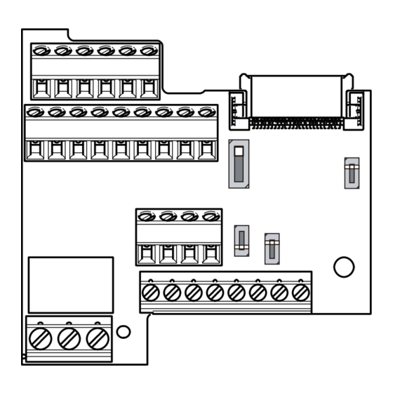
1.1.3 Component names Front view Rear view SINK OPEN SOURCE Ω Symbol Name Description Refer to page Used to connect the device to input signals to the inverter, and the device Terminal block to receive the signal from the inverter. Board mounted option Connected to the control circuit connection connector of the inverter. - Page 10 Symbol Name Description Refer to page For terminal 4 used for analog input, the voltage input (0 to 5 V, 0 to 10 V) and current input (4 to 20 mA) (initial setting) are selectable. To change the Voltage/current input switch input specification, change the setting of Pr.267 and the voltage/current input switch.
-
Page 11: Terminal Layout
1.1.4 Terminal layout STF STR STR SD RUN FU RH MRS MRS RES RES PC SINK OPEN SOURCE Ω SDA SDB SDB RDA RDA RDB SDA SDB SDB RDA PRE-OPERATION INSTRUCTIONS... -
Page 12: Terminal Connection Diagram
Terminal connection diagram Control input signals (No voltage input allowed) Relay output Forward rotation start The function of these The function of these terminals can be changed terminals can be changed Relay output using the Input terminal Reverse rotation start using the Pr.192 ABC (Fault output) function selection... - Page 13 To use terminals PC and SD for a 24 VDC power supply, check the wiring to avoid short circuit between these terminals. Terminal input specifications can be changed by analog input specification switchover (Pr.73). This terminal is used for voltage input only. Terminal input specifications can be changed by analog input specification switchover (Pr.267).
-
Page 14: Control Terminal Specifications
Control terminal specifications RS-485 communication Terminal Terminal name Terminal function description symbol SDA (2 terminals) Inverter send + Output terminal for inverter sending signals. SDB (2 terminals) Inverter send - Output terminal for inverter inverse sending signals. Input terminal for inverter receiving signals. RDA (2 terminals) Inverter receive + Changing the terminating resistor switch to "100 Ω"... - Page 15 Frequency setting Terminal Common Terminal name Terminal function description Rated specification symbol Power supply for a Used as the power supply for an external frequency 5 ±0.5 VDC frequency setting setting (speed setting) potentiometer. Permissible load current: 10 mA potentiometer Input resistance: 10 to 11 kΩ...
- Page 16 Input signal (contact input) Terminal Common Terminal name Terminal function description Rated specification symbol Turn ON the STF signal to Forward rotation start forward rotation and When the STF and STR start turn it OFF to stop. signals are turned ON simultaneously, the stop Turn ON the STR signal to Reverse rotation...
- Page 17 Output signal Terminal Type Common Terminal name Terminal function description Rated specification symbol 1 changeover contact output that indicates that an inverter's protective function has been Contact capacity: 230 Relay output (fault activated and the outputs are stopped. VAC 0.3 A (power factor *1*3 Relay —...
- Page 18 Common terminal Terminal Rated Common Terminal name Terminal function description symbol specification Common terminal for RS-485 communication and RS-485 communication — frequency setting signals (terminal 2 or 4). Do not earth — common, analog common (ground). Contact input common (sink Common terminal for the contact input terminal (sink logic) (negative common)) and terminal FM.
- Page 19 NOTE • Terminals SD, SG and SE are common terminals for I/O signals. (All common terminals are isolated from each other.) Do not earth (ground) these terminals. Avoid connecting terminals SD and SG and terminals SE and SG. • Terminal SD is a common terminal for the contact input terminals (STF, STR, RH, RM, RL, MRS, and RES) and the pulse train output terminal (FM).
-
Page 20: Communication Specifications
Communication specifications Item Description Communication Mitsubishi inverter protocol MODBUS RTU protocol BACnet MS / TP protocol protocol (computer link) Conforming EIA-485 (RS-485) standard Number of 1:N (maximum 32 units), for stations No. 1:N (maximum 32 units), for stations No. 255 (up to 32 for one segment, connectable 0 to 31 0 to 247... -
Page 21: Installation
INSTALLATION Pre-installation instructions Check that all the power supplies to be input to the inverter are OFF. CAUTION • Do not install or remove the control terminal option while the input power is ON. Doing so may damage the inverter or the control terminal option. -
Page 22: Installation Procedure
Installation procedure Remove the inverter front cover. (Refer to the FR-E800 Instruction Manual (Connection) for instructions to remove the cover.) Remove the installation screw of the standard control circuit terminal block. Slide down the standard control circuit terminal block to remove it. Remove the screw. - Page 23 Be careful not to bend the pins of the inverter's control circuit connector, insert the control terminal option and fix it with the installation screw. (Tightening torque: 0.33 to 0.40 N·m) Tighten the screw. INSTALLATION...
- Page 24 Affix the control terminal change indication label, which is enclosed with this product, next to the model name on the front cover to indicate that the control terminal block has been replaced with the FR-E8TR. (Two control terminal change indication labels are provided. One of them is a spare.)
- Page 25 Removal and reinstallation precautions Precautions to be taken when removing or reinstalling the control circuit terminal block are shown below. Observe the following precautions and handle the inverter properly to avoid malfunctions or failures. • To remove or reinstall the control circuit terminal block, keep it upright so that it is parallel with the inverter. •...
- Page 26 NOTE • Do not tilt the terminal block while tightening the screws or removing it from the inverter. (Otherwise, stress applied to the control circuit terminal block or the control circuit connector may damage the pins.) • After replacing the control terminal block, set the control logic switch to the correct position in accordance with the control logic of input signals.
-
Page 27: Wiring
WIRING System configuration of RS-485 terminals Computer and inverter connection (1:1) Computer Computer Inverter Inverter RS-485 RS-485 terminals terminals Maximum RS-232C cable RS-485 interface terminal Converter Twisted pair cable Twisted pair cable 500m or less 500m or less overall wiring length overall wiring length *1 Set the terminating resistor switch to the "100Ω"... - Page 28 Combination of a computer and multiple inverters (1:n) Station 0 Station 1 Station n Computer Inverter Inverter Inverter RS-485 RS-485 RS-485 terminals terminals terminals RS-485 interface terminal *1 Set only the terminating resistor switch of the remotest inverter to Twisted pair cable the "100 Ω"...
-
Page 29: Rs-485 Terminal Wiring Method
RS-485 terminal wiring method Four-wire type connection Wiring between a computer and multiple inverters for RS-485 communication Computer *1 Receiving Sending Station 0 Station 1 Station n Make connection in accordance with the Instruction Manual of the computer to be used with. Fully check the terminal numbers of the computer since they vary with the model. - Page 30 NOTE • Refer to the following figure for branch wiring in the case of full-duplex system. RES PC SINK OPEN Set only the terminating resistor switch of the remotest inverter to the Use terminal 2 as terminal SG by setting the SOURCE "100 Ω"...
- Page 31 Two-wire type connection If the computer is 2-wire type, a connection from the inverter can be changed to 2-wire type by passing wires across reception terminals and transmission terminals of the RS-485 terminals. Pass a wire Computer *1 Transmission enable Reception enable...
- Page 32 NOTE • Refer to the following figure for branch wiring in the case of half-duplex system. RES PC SINK OPEN Set only the terminating resistor switch of the remotest inverter to the Use terminal 2 as terminal SG by setting the SOURCE "100 Ω"...
-
Page 33: Wiring
Wiring For the wiring, strip off the sheath of a cable, and use it with a crimp terminal. For a single wire, strip off the sheath of the wire and apply directly. Insert the crimp terminal or the single wire into a socket of the terminal. Strip the signal wires as follows. - Page 34 Crimp the terminals on the wire. Insert the wire into a crimp terminal, making sure that 0 to 0.5 mm of the wire protrudes from the end of the sleeve. Check the condition of the crimp terminals after crimping. Do not use the crimp terminals of which the crimping is inappropriate, or the face is damaged.
- Page 35 NOTE Crimp terminals commercially available (as of October 2020) • Phoenix Contact Co., Ltd. Ferrule part No. Terminal screw size Crimping tool model No. Wire gauge (mm With insulation sleeve Without insulation sleeve AI 0,34-6TQ A 0,5-6 M3 (Terminals A, B, C) AI 0,5-6WH A 0,5-6 CRIMPFOX 6...
-
Page 36: Operation Via Communication From Rs-485 Terminals
OPERATION VIA COMMUNICATION FROM RS-485 TERMINALS Installing the control terminal option FR-E8TR allows RS-485 communication via the RS-485 terminals instead of the PU connector on the standard control circuit terminal block. Required parameter settings (refer to page 37) are the same as those for RS-485 communication via the PU connector. -
Page 37: Parameter List
Parameter list The following parameters are used for RS-485 communication with the FR-E8TR. Set the parameters as required. For the parameter details, refer to the FR-E800 Instruction Manual (Function) and the FR- E800 Instruction Manual (Communication). Initial Name Setting range... - Page 38 Initial Name Setting range Description value Set the permissible number of retries for unsuccessful data reception. If the number of 0 to 10 consecutive errors exceeds the permissible Number of PU communication retries value, the inverter output is shut off. N025 The inverter output will not be shut off even 9999...
- Page 39 Initial Name Setting range Description value The communication option is the command source in the NET operation mode. The RS-485 terminals are the command source in the NET operation mode. NET mode operation command source Communication option is recognized 9999 D012 selection automatically.
- Page 40 Initial Name Setting range Description value 0 to 419 Device identifier Device instance number (Upper 3 digits) N052 (0 to 418) When the figure obtained by combining the Pr.728 and Pr.729 settings is not within "0 to 4194302", the setting is out of range. When Pr.728 = "419", the setting range of Pr.729 0 to 9999 Device instance number (Lower 4 digits)
-
Page 41: Analog Input Selection
Analog input selection The analog terminal specification and the function to switch forward/reverse rotation by the input signal can be selected. Initial Name Setting range Description value The terminal 2 input specification (0 to 5 V, 0 to 0, 1, 6 , 10, 11, Analog input selection 10 V) is selectable. - Page 42 COMMON SPECIFICATIONS Environment Item Specifications Surrounding air temperature -10°C to +50°C (non-freezing) Surrounding air humidity 90% RH or less (non-condensing) -20°C to +65°C Storage temperature Atmosphere Indoors (free from corrosive gas, flammable gas, oil mist, dust and dirt) Altitude/vibration Maximum 1000 m, 5.9 m/s or less at 10 to 55 Hz (directions of X, Y, Z axes) Temperature applicable for a short time, for example, in transit.
- Page 43 Revisions *The manual number is given on the bottom left of the back cover. Revision date * Manual number Revision Jun. 2023 IB(NA)-0601001ENG-A First edition...
- Page 44 INVERTER HEAD OFFICE: TOKYO BUILDING 2-7-3, MARUNOUCHI, CHIYODA-KU, TOKYO 100-8310, JAPAN IB(NA)-0601001ENG-A(2306) MEE Printed in Japan Specifications subject to change without notice.