Advertisement
Quick Links
Advertisement

Related Manuals for Seco SBC-984


Summary of Contents for Seco SBC-984
- Page 1 SBC-984 Single Board Computer with NXP i.MX6 Processor...
- Page 2 SECO S.r.l. reserves the right to change precise specifications without prior notice to supply the best product possible. For further information on this module or other SECO products, but also to get the required assistance for any and possible issues, please contact us using the dedicated web form available at http://www.seco.com (registration required).
- Page 3 Half-mini PCI-express / mSATA slot ...................................... 29 3.3.7 Serial port RS-232 ..........................................30 3.3.8 CAN Bus connector ..........................................31 SBC-984 SBC-984 User Manual - Rev. First Edition: 1.0 - Last Edition: 4.0 - Author: S.B. - Reviewed by N.P. Copyright © 2016 SECO S.r.l.
- Page 4 CSI Dongle Camera VA09 ........................................36 4.2.5 Accessories kit CABKIT984REVC ......................................36 4.2.6 7” Display Kit ............................................37 SBC-984 SBC-984 User Manual - Rev. First Edition: 1.0 - Last Edition: 4.0 - Author: S.B. - Reviewed by N.P. Copyright © 2016 SECO S.r.l.
- Page 5 Information and assistance RMA number request Safety Electrostatic discharges RoHS compliance Terminology and definitions Reference specifications SBC-984 SBC-984 User Manual - Rev. First Edition: 1.0 - Last Edition: 4.0 - Author: S.B. - Reviewed by N.P. Copyright © 2016 SECO S.r.l.
- Page 6 All changes or modifications to the equipment not explicitly approved by SECO S.r.l. could impair the equipment s functionality and could void the warranty SBC-984 SBC-984 User Manual - Rev. First Edition: 1.0 - Last Edition: 4.0 - Author: S.B. - Reviewed by N.P. Copyright © 2016 SECO S.r.l.
- Page 7 A RMA Number will be sent within 1 working day (only for on-line RMA requests). SBC-984 SBC-984 User Manual - Rev. First Edition: 1.0 - Last Edition: 4.0 - Author: S.B. - Reviewed by N.P. Copyright © 2016 SECO S.r.l.
- Page 8 Check carefully that all cables are correctly connected and that they are not damaged. 1.5 Electrostatic discharges The SBC-984 board, like any other electronic product, is an electrostatic sensitive device: high voltages caused by static electricity could damage some or all the devices and/or components on-board.
- Page 9 MMC, i.e. they are devices that incorporate the memory controller and the flash memories on a single BGA chip N.A. Not Applicable N.C. Not Connected SBC-984 SBC-984 User Manual - Rev. First Edition: 1.0 - Last Edition: 4.0 - Author: S.B. - Reviewed by N.P. Copyright © 2016 SECO S.r.l.
- Page 10 Transistor-transistor Logic Universal Serial Bus uSDHC Ultra Secure Digital Host Controller V_REF Voltage reference Pin SBC-984 SBC-984 User Manual - Rev. First Edition: 1.0 - Last Edition: 4.0 - Author: S.B. - Reviewed by N.P. Copyright © 2016 SECO S.r.l.
- Page 11 SM Bus http://www.smbus.org/specs TMDS http://www.siliconimage.com/technologies/tmds USB 2.0 and USB OTG http://www.usb.org/developers/docs/usb_20_070113.zip http://www.nxp.com/products/microcontrollers-and-processors/arm-processors/i.mx-applications-processors-based-on-arm- NXP i.MX6 processor cores/i.mx-6-processors:IMX6X_SERIES?cof=0&am=0 SBC-984 SBC-984 User Manual - Rev. First Edition: 1.0 - Last Edition: 4.0 - Author: S.B. - Reviewed by N.P. Copyright © 2016 SECO S.r.l.
- Page 12 Chapter 2. Introduction Technical specifications Electrical specifications Mechanical specifications Block diagram SBC-984 SBC-984 User Manual - Rev. First Edition: 1.0 - Last Edition: 4.0 - Author: S.B. - Reviewed by N.P. Copyright © 2016 SECO S.r.l.
- Page 13 Please refer to following chapter for a complete list of all peripherals integrated and characteristics. SBC-984 SBC-984 User Manual - Rev. First Edition: 1.0 - Last Edition: 4.0 - Author: S.B. - Reviewed by N.P. Copyright © 2016 SECO S.r.l.
- Page 14 2.2 Technical specifications Processors ® NXP i.MX6 Family, based on ARM CORTEX-A9 processors 3 x standard USB 2.0 Type A 1 x USB OTG on micro-AB connector i.MX6S Solo - Single core up to 1GHz Internal USB for optional WiFi module i.MX6D Dual - Dual core up to 1.2GHz per core i.MX6DL Dual Lite - Dual core up to 1GHz per core Networking...
- Page 15 2.3 Electrical specifications SBC-984 needs to be supplied only with an external 12V ± 10% power supply. This voltage can be supplied through a standard 6.3mm (internal pin, diameter 2.0 mm) Power Jack. Internal pin is V power line. can also be supplied using dedicated internal connector J8, which is a MOLEX “Micro-Fit...
- Page 16 270 Mbits/sec RX 270 Mbits/sec RX 130Mbits/sec TX 140Mbits/sec TX 140Mbits/sec TX Stress test 4.69W 6.11W 9.81W SBC-984 SBC-984 User Manual - Rev. First Edition: 1.0 - Last Edition: 4.0 - Author: S.B. - Reviewed by N.P. Copyright © 2016 SECO S.r.l.
- Page 17 Batteries supplied with SBC-984 are compliant to requirements of European Directive 2006/66/EC regarding batteries and accumulators. When putting out of order SBC-984, remove the batteries from the board in order to collect and dispose them according to the requirement of the same European Directive above mentioned.
- Page 18 The printed circuit of the board is made of twelve layers, some of them are ground planes, for disturbance rejection. SBC-984 SBC-984 User Manual - Rev. First Edition: 1.0 - Last Edition: 4.0 - Author: S.B. - Reviewed by N.P. Copyright © 2016 SECO S.r.l.
- Page 19 Camera interface DDR3 System NXP PCF2123 SPI Power section Low Power RTC Memory +12V SBC-984 SBC-984 User Manual - Rev. First Edition: 1.0 - Last Edition: 4.0 - Author: S.B. - Reviewed by N.P. Copyright © 2016 SECO S.r.l.
- Page 20 Chapter 3. Introduction Connectors overview Connectors description SBC-984 SBC-984 User Manual - Rev. First Edition: 1.0 - Last Edition: 4.0 - Author: S.B. - Reviewed by N.P. Copyright © 2016 SECO S.r.l.
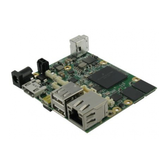
- Page 21 3.1 Introduction On SBC-984 board, there are several connectors located on the upper plane. Standard connectors are placed on the same side of PCB, so that it is possible to place them on a panel of an eventual enclosure. Please be aware that, depending on the configuration purchased, the appearance of the board could be slightly different from the following pictures.
- Page 22 Camera connector (only PCB rev. C or higher) MFG + Audio + Power/Reset buttons connector LVDS connector SBC-984 SBC-984 User Manual - Rev. First Edition: 1.0 - Last Edition: 4.0 - Author: S.B. - Reviewed by N.P. Copyright © 2016 SECO S.r.l.
- Page 23 LVDS0_TX2+/LVDS0_TX2-: LVDS Channel #0 differential data pair #2. LVDS0_TX3+/LVDS0_TX3-: LVDS Channel #0 differential data pair #3. LVDS0_CLK+/LVDS0_CLK-: LVDS Channel #0 differential Clock. SBC-984 SBC-984 User Manual - Rev. First Edition: 1.0 - Last Edition: 4.0 - Author: S.B. - Reviewed by N.P. Copyright © 2016 SECO S.r.l.
- Page 24 Always use HDMI-certified cables for the connection between the board and the HDMI display; a category 2 (High-Speed) cable is recommended for higher resolutions, category 1 cables can be used for 720p resolution. SBC-984 SBC-984 User Manual - Rev. First Edition: 1.0 - Last Edition: 4.0 - Author: S.B. - Reviewed by N.P. Copyright © 2016 SECO S.r.l.
- Page 25 GBE0_MDI3+/GBE0_MDI3-: Ethernet Controller Media Dependent Interface (MDI) I/O differential pair #3. It is the fourth differential pair in Gigabit Ethernet mode; it is not used in 10/100Mbps modes. SBC-984 SBC-984 User Manual - Rev. First Edition: 1.0 - Last Edition: 4.0 - Author: S.B. - Reviewed by N.P. Copyright © 2016 SECO S.r.l.
- Page 26 “rear” side of the board, on a vertical, right-angle, standard USB Type A socket. USB_H2+ SBC-984 SBC-984 User Manual - Rev. First Edition: 1.0 - Last Edition: 4.0 - Author: S.B. - Reviewed by N.P. Copyright © 2016 SECO S.r.l.
- Page 27 USB_ID: USB Identification pin. It is the signal used in the micro-AB connectors to differentiate between micro-A cables (to be used for Host connection) and micro-B cables (to be used for Client connection). SBC-984 SBC-984 User Manual - Rev. First Edition: 1.0 - Last Edition: 4.0 - Author: S.B. - Reviewed by N.P. Copyright © 2016 SECO S.r.l.
- Page 28 Finally, this same connector carries out two signals (MSP_TEST and MSP_RST) that are used for manufacturing purposes, and shall therefore not be used by the customer. SBC-984 SBC-984 User Manual - Rev. First Edition: 1.0 - Last Edition: 4.0 - Author: S.B. - Reviewed by N.P. Copyright © 2016 SECO S.r.l.
- Page 29 SMB_CLK: SM Bus control clock line for System Management. Output signal, electrical level +3.3V_S with a 4k7Ω pull-up resistor. N.C. N.C. +3.3V_A SBC-984 SBC-984 User Manual - Rev. First Edition: 1.0 - Last Edition: 4.0 - Author: S.B. - Reviewed by N.P. Copyright © 2016 SECO S.r.l.
- Page 30 RX: Serial port interface, data receive line, ± 15kV ESD Protected, RS-232 compatible receiver input. SBC-984 SBC-984 User Manual - Rev. First Edition: 1.0 - Last Edition: 4.0 - Author: S.B. - Reviewed by N.P. Copyright © 2016 SECO S.r.l.
- Page 31 A 120Ω termination resistor is placed between CAN_H and CAN_L signals. It can be connected or disconnected from the line by using an analog switch, which is managed via SW. If necessary, SECO can provide for a DB-9 male adapter cable for direct connection of the module to an existing CAN Bus line. Please check par. 4.2.5. 3.3.9 Debug UART / I2C Touch Connector...
- Page 32 For normal working of the board, this jumper must not be inserted. It has to be plugged only in case the system must be reprogrammed. SBC-984 SBC-984 User Manual - Rev. First Edition: 1.0 - Last Edition: 4.0 - Author: S.B. - Reviewed by N.P. Copyright © 2016 SECO S.r.l.
- Page 33 Chapter 4. Thermal Design Accessories SBC-984 SBC-984 User Manual - Rev. First Edition: 1.0 - Last Edition: 4.0 - Author: S.B. - Reviewed by N.P. Copyright © 2016 SECO S.r.l.
- Page 34 SECO can provide the customer with SBC-984 specific heatspreader and/or passive heatsink, which will act ONLY as a thermal coupling device. It is not intended to be a stand-alone cooling system, but a means of transferring heat to an external, passive or active cooling element, like heatsinks, fans, heat pipes, etc. The SECO heatspreader is thermally coupled to the most critical heat - generating board components and surfaces using a thermal gap pad, which optimizes the heat exchange between the module and the heatspreader.
- Page 35 SECO, and whose drivers are already included in SECO’s provided BSPs. Please contact SECO for ordering p/n. SBC-984 SBC-984 User Manual - Rev. First Edition: 1.0 - Last Edition: 4.0 - Author: S.B. - Reviewed by N.P. Copyright © 2016 SECO S.r.l.
- Page 36 Power button, reset button, Line Out jack, Mic in Jack adapter cable, can be connected to board’s connector J11. SBC-984 SBC-984 User Manual - Rev. First Edition: 1.0 - Last Edition: 4.0 - Author: S.B. - Reviewed by N.P. Copyright © 2016 SECO S.r.l.
- Page 37 The other side of the cable only needs to be plugged into adapter’s module’s connector CN1. Please contact SECO for ordering p/n. SBC-984 SBC-984 User Manual - Rev. First Edition: 1.0 - Last Edition: 4.0 - Author: S.B. - Reviewed by N.P. Copyright © 2016 SECO S.r.l.
- Page 38 SECO Srl - Via Calamandrei 91 52100 Arezzo - ITALY Ph: +39 0575 26979 - Fax: +39 0575 350210 www.seco.com SBC-984 SBC-984 User Manual - Rev. First Edition: 1.0 - Last Edition: 4.0 - Author: S.B. - Reviewed by N.P. Copyright © 2016 SECO S.r.l.
Need help?
Do you have a question about the SBC-984 and is the answer not in the manual?
Questions and answers