
Subscribe to Our Youtube Channel
Related Manuals for Seco SBC-C61


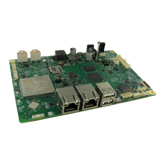
Summary of Contents for Seco SBC-C61
- Page 1 SBC-C61 Single Board Computer with the NXP i.MX 8M Mini Processors on 3.5” form factor...
- Page 2 SECO S.p.A. reserves the right to change precise specifications without prior notice to supply the best product possible. For further information on this module or other SECO products, but also to get the required assistance for any and possible issues, please contact us using the dedicated web form available at http://www.seco.com (registration required).
-
Page 3: Table Of Contents
3.3.6 Optional LED Driver Connector ...................................... 29 3.3.7 I2C Touch Screen Connector ....................................... 29 SBC-C61 SBC-C61 User Manual - Rev. First Edition: 1.0 - Last Edition: 1.1 - Author: S.B. - Reviewed by N.P. - Copyright © 2021 SECO S.p.A. - Page 4 JTAG Connector.......................................... 37 3.3.15 ON/OFF and Reset Connector ...................................... 38 APPENDICES .....................................39 Thermal Design ........................................... 40 SBC-C61 SBC-C61 User Manual - Rev. First Edition: 1.0 - Last Edition: 1.1 - Author: S.B. - Reviewed by N.P. - Copyright © 2021 SECO S.p.A.
-
Page 5: Introduction
Electrostatic discharges • RoHS compliance • Safety Policy • Terminology and definitions • Reference specifications SBC-C61 SBC-C61 User Manual - Rev. First Edition: 1.0 - Last Edition: 1.1 - Author: S.B. - Reviewed by N.P. - Copyright © 2021 SECO S.p.A. -
Page 6: Warranty
All changes or modifications to the equipment not explicitly approved by SECO S.p.A. could impair the equipment s functionalities and could void the warranty. SBC-C61 SBC-C61 User Manual - Rev. First Edition: 1.0 - Last Edition: 1.1 - Author: S.B. - Reviewed by N.P. - Copyright © 2021 SECO S.p.A. -
Page 7: Information And Assistance
A RMA Number will be sent within 1 working day (only for on-line RMA requests). SBC-C61 SBC-C61 User Manual - Rev. First Edition: 1.0 - Last Edition: 1.1 - Author: S.B. - Reviewed by N.P. - Copyright © 2021 SECO S.p.A. -
Page 8: Safety
Check carefully that all cables are correctly connected and that they are not damaged. 1.5 Electrostatic discharges The SBC-C61 board, like any other electronic product, is an electrostatic sensitive device: high voltages caused by static electricity could damage some or all the devices and/or components on-board. -
Page 9: Safety Policy
The board shall be powered by a Power Supply Unit separately approved and classified ES1/PS2 according to the requirements of IEC EN 62368-1. SBC-C61 SBC-C61 User Manual - Rev. First Edition: 1.0 - Last Edition: 1.1 - Author: S.B. - Reviewed by N.P. - Copyright © 2021 SECO S.p.A. -
Page 10: Terminology And Definitions
Abbreviation of Physical, it is the device implementing the Physical Layer of ISO/OSI-7 model for communication systems Power Supply Unit Pulse Width Modulation SBC-C61 SBC-C61 User Manual - Rev. First Edition: 1.0 - Last Edition: 1.1 - Author: S.B. - Reviewed by N.P. - Copyright © 2021 SECO S.p.A. - Page 11 User Identity Module, an extension of SIM modules. Universal Serial Bus uSDHC Ultra Secure Digital Host Controller V_REF Voltage reference Pin SBC-C61 SBC-C61 User Manual - Rev. First Edition: 1.0 - Last Edition: 1.1 - Author: S.B. - Reviewed by N.P. - Copyright © 2021 SECO S.p.A.
-
Page 12: Reference Specifications
SD Card Association https://www.sdcard.org/home SDIO https://www.sdcard.org/developers/overview/sdio SM Bus http://www.smbus.org/specs USB 2.0 and USB OTG https://www.usb.org/sites/default/files/usb_20_20190524.zip SBC-C61 SBC-C61 User Manual - Rev. First Edition: 1.0 - Last Edition: 1.1 - Author: S.B. - Reviewed by N.P. - Copyright © 2021 SECO S.p.A. -
Page 13: Overview
• Introduction • Technical specifications • Electrical specifications • Mechanical specifications • Block diagram SBC-C61 SBC-C61 User Manual - Rev. First Edition: 1.0 - Last Edition: 1.1 - Author: S.B. - Reviewed by N.P. - Copyright © 2021 SECO S.p.A. -
Page 14: Introduction
An LTE Cat4 module, Quectel EG-25, with dedicated micro-SIM slot is also available as a factory option The SBC-C61 board offers two USB 2.0 standard Type-A connectors, an internal header with two additional USB 2.0 Host ports and an USB 2.0 port on micro-AB connector (this interface is shared with the optional modem). -
Page 15: Technical Specifications
Optional Shielded Ultra Small Dual Band WiFi 802.11 a/b/g/n/ac with Bluetooth 5.0 Module onboard ** Measured at any point of SECO standard heatsink for this product, during Optional soldered on-board LTE Cat 4 Modem with microSIM slot or Telenor any and all times (including start-up). Actual temperature will widely depend eSIM with 5MB Bundle on application, enclosure and/or environment. -
Page 16: Electrical Specifications
Batteries supplied with SC61 are compliant to requirements of European Directive 2006/66/EC regarding batteries and accumulators. When putting out of order SBC-C61, remove the batteries from the board in order to collect and dispose them according to the requirement of the same European Directive above mentioned. -
Page 17: Power Rails
Storage: 4GB eMMC; Video Interface: eDP; Networking: 2x Gigabit LAN + WiFi with u.FL Connector; SBC-C61 SBC-C61 User Manual - Rev. First Edition: 1.0 - Last Edition: 1.1 - Author: S.B. - Reviewed by N.P. - Copyright © 2021 SECO S.p.A. - Page 18 Reproduction FullHD (*) Idle optimized: Modem not powered, WiFi/BT disabled, Eth0 disabled, video disabled SBC-C61 SBC-C61 User Manual - Rev. First Edition: 1.0 - Last Edition: 1.1 - Author: S.B. - Reviewed by N.P. - Copyright © 2021 SECO S.p.A.
-
Page 19: Mechanical Specifications
The printed circuit of the board is made of ten layers, some of them are ground planes, for disturbance rejection. SBC-C61 SBC-C61 User Manual - Rev. First Edition: 1.0 - Last Edition: 1.1 - Author: S.B. - Reviewed by N.P. - Copyright © 2021 SECO S.p.A. -
Page 20: Block Diagram
2.5 Block diagram SBC-C61 SBC-C61 User Manual - Rev. First Edition: 1.0 - Last Edition: 1.1 - Author: S.B. - Reviewed by N.P. - Copyright © 2021 SECO S.p.A. -
Page 21: Connectors
• Introduction • Connectors overview • Connectors description SBC-C61 SBC-C61 User Manual - Rev. First Edition: 1.0 - Last Edition: 1.1 - Author: S.B. - Reviewed by N.P. - Copyright © 2021 SECO S.p.A. -
Page 22: Introduction
3.1 Introduction On SBC-C61 board, there are several connectors located on the lower plane. Standard connectors are placed on the same side of PCB, so that it is possible to place them on a panel of an eventual enclosure. Please be aware that, depending on the configuration purchased, the appearance of the board could be different from the following pictures. -
Page 23: Connectors Overview
LCD Power selector CAN1 Bus Termination CN35 Backlight Power selector CAN2 Bus Termination CN52 Boot Mode SBC-C61 SBC-C61 User Manual - Rev. First Edition: 1.0 - Last Edition: 1.1 - Author: S.B. - Reviewed by N.P. - Copyright © 2021 SECO S.p.A. -
Page 24: Connectors Description
GBEx_MDI3+/GBEx_MDI3-: Ethernet Controller #x Media Dependent Interface (MDI) I/O differential pair #3. It is the fourth differential pair in Gigabit Ethernet mode; it is not used in 10/100Mbps modes. SBC-C61 SBC-C61 User Manual - Rev. First Edition: 1.0 - Last Edition: 1.1 - Author: S.B. - Reviewed by N.P. - Copyright © 2021 SECO S.p.A. -
Page 25: On Board Optional Modem
This optional WiFi + BT module, as a further factory option, can be equipped with a PCB ceramic chip antenna (PulseLarsen W3006) or with an U.FL connector (CN17, type HIROSE U.FL-R-SMT1(10) )for external antenna. SBC-C61 SBC-C61 User Manual - Rev. First Edition: 1.0 - Last Edition: 1.1 - Author: S.B. - Reviewed by N.P. - Copyright © 2021 SECO S.p.A. -
Page 26: Lvds Connector
LVDS_1_TX1+/ LVDS_1_TX1-: LVDS Channel #1 differential data pair #1. TOUCH_SDA TOUCH_INT# LVDS_1_TX2+/ LVDS_1_TX2-: LVDS Channel #1 differential data pair #2. SBC-C61 SBC-C61 User Manual - Rev. First Edition: 1.0 - Last Edition: 1.1 - Author: S.B. - Reviewed by N.P. - Copyright © 2021 SECO S.p.A. - Page 27 For this purpose, some dedicated 0-Ohm resistors can be mounted (factory default: not available). Please contact you local Sales rep in case you need this special configuration. SBC-C61 SBC-C61 User Manual - Rev. First Edition: 1.0 - Last Edition: 1.1 - Author: S.B. - Reviewed by N.P. - Copyright © 2021 SECO S.p.A.
-
Page 28: Edp Connector
BKLT_PWM: this signal can be used to adjust the backlight brightness in displays supporting eDP_ML2N Pulse Width Modulated (PWM) regulations (LCD_PWR electrical level). eDP_ML3P eDP_ML3N LCD_PWR SBC-C61 SBC-C61 User Manual - Rev. First Edition: 1.0 - Last Edition: 1.1 - Author: S.B. - Reviewed by N.P. - Copyright © 2021 SECO S.p.A. -
Page 29: Optional Led Driver Connector
The signals available on this connector are exactly the same available on LVDS connector CN40. Please look at par. 3.3.4. TOUCH_SDA for their description. TOUCH_SCL TOUCH_RST SBC-C61 SBC-C61 User Manual - Rev. First Edition: 1.0 - Last Edition: 1.1 - Author: S.B. - Reviewed by N.P. - Copyright © 2021 SECO S.p.A. - Page 30 When connecting CSI cameras to CN16 connector, it is strongly recommended to use shielded cable for EMC compatibility. SBC-C61 SBC-C61 User Manual - Rev. First Edition: 1.0 - Last Edition: 1.1 - Author: S.B. - Reviewed by N.P. - Copyright © 2021 SECO S.p.A.
- Page 31 USB1+/USB1-: USB Hub Downstream port #1 differential pair. USB1+ USB2+ USB2+/USB2-: USB Hub Downstream port #2 differential pair. SBC-C61 SBC-C61 User Manual - Rev. First Edition: 1.0 - Last Edition: 1.1 - Author: S.B. - Reviewed by N.P. - Copyright © 2021 SECO S.p.A.
- Page 32 These connectors are type MOLEX 53398-0571 or equivalent, with the pinouts shown in the tables in the next page. Mating connectors: MOLEX 51021-0500 receptacle with MOLEX 50079-8000 female crimp terminals. SBC-C61 SBC-C61 User Manual - Rev. First Edition: 1.0 - Last Edition: 1.1 - Author: S.B. - Reviewed by N.P. - Copyright © 2021 SECO S.p.A.
- Page 33 M4_DUART_TX: UART port #4 Transmit signal, VDD_3V3 electrical level. VDD_3V3 M4_DUART_TX M4_DUART_RX: UART port #4 Receive signal, VDD_3V3 electrical level. M4_DUART_RX SBC-C61 SBC-C61 User Manual - Rev. First Edition: 1.0 - Last Edition: 1.1 - Author: S.B. - Reviewed by N.P. - Copyright © 2021 SECO S.p.A.
- Page 34 This means that there are 16 possible configurations of these interfaces. Please be aware that the board’s configuration with SBC-C61 SBC-C61 User Manual - Rev. First Edition: 1.0 - Last Edition: 1.1 - Author: S.B. - Reviewed by N.P. - Copyright © 2021 SECO S.p.A.
- Page 35 RS232_1_TX : COM Port #3 RS-232 Mode Transmit data RS232_1_RTS : COM Port #3 RS-232 Mode Request to Send handshaking signal. SBC-C61 SBC-C61 User Manual - Rev. First Edition: 1.0 - Last Edition: 1.1 - Author: S.B. - Reviewed by N.P. - Copyright © 2021 SECO S.p.A.
- Page 36 OUT4 ECSPI1_SS0 CN55-6 OUT5 ECSPI2_MOSI CN55-7 OUT6 ECSPI2_MISO CN55-8 OUT7 ECSPI2_SCLK CN55-9 OUT8 ECSPI2_SS0 SBC-C61 SBC-C61 User Manual - Rev. First Edition: 1.0 - Last Edition: 1.1 - Author: S.B. - Reviewed by N.P. - Copyright © 2021 SECO S.p.A.
- Page 37 All these JTAG signals are directly connected to i.MX8 pins with same name. Please refer to i.MX8M Mini processor’s JTAG_TDI documentation for a description of the signals and their usage. JTAG_TDO JTAG_TRST_B SBC-C61 SBC-C61 User Manual - Rev. First Edition: 1.0 - Last Edition: 1.1 - Author: S.B. - Reviewed by N.P. - Copyright © 2021 SECO S.p.A.
- Page 38 ONOFF ONOFF: Reset Input, active Low signal. Electrical Level NVCC_SNVS_1V8 with 4.7kΩ pull-up resistor SBC-C61 SBC-C61 User Manual - Rev. First Edition: 1.0 - Last Edition: 1.1 - Author: S.B. - Reviewed by N.P. - Copyright © 2021 SECO S.p.A.
- Page 39 • Thermal Design SBC-C61 SBC-C61 User Manual - Rev. First Edition: 1.0 - Last Edition: 1.1 - Author: S.B. - Reviewed by N.P. - Copyright © 2021 SECO S.p.A.
- Page 40 When using SBC-C61 boards, it is necessary to consider carefully the heat generated by the module in the assembled final system, and the scenario of utilization. Until the board is used on a laboratory shelf, on free air, just for software development and system tuning, then a heatsink with integrated fan could be sufficient for board’s cooling.
- Page 41 52100 Arezzo - ITALY Ph: +39 0575 26979 - Fax: +39 0575 350210 www.seco.com SBC-C61 SBC-C61 User Manual - Rev. First Edition: 1.0 - Last Edition: 1.1 - Author: S.B. - Reviewed by N.P. - Copyright © 2021 SECO S.p.A.
Need help?
Do you have a question about the SBC-C61 and is the answer not in the manual?
Questions and answers