Advertisement
Quick Links
Binary Blaster Assembly Guide
Introduction
Binary Blaster is a game that helps teach the player how to count in binary
as well as convert from decimal (and hexadecimal) to binary and back,
quickly. It displays a value on the 7 segment display, and the player is
challenged to press the buttons in a way that represents the binary
equivalent. Press a button to "set" that bit. Leave a button alone to "clear"
that bit. There are four buttons, each one represents a bit. This means
there are 15 possibilities. If the player gets all 15 correct, they win! It also
displays a time score, so you can keep track of your fastest speed and
practice to get faster!
This product comes as a PTH soldering kit, and it's up to you to solder it all
together! You can buy the complete kit here.
If you're new to soldering, the Binary Blaster PTH Kit is a great place to
start. This assembly guide will take you through each component in the kit
and show you how to solder it into place.
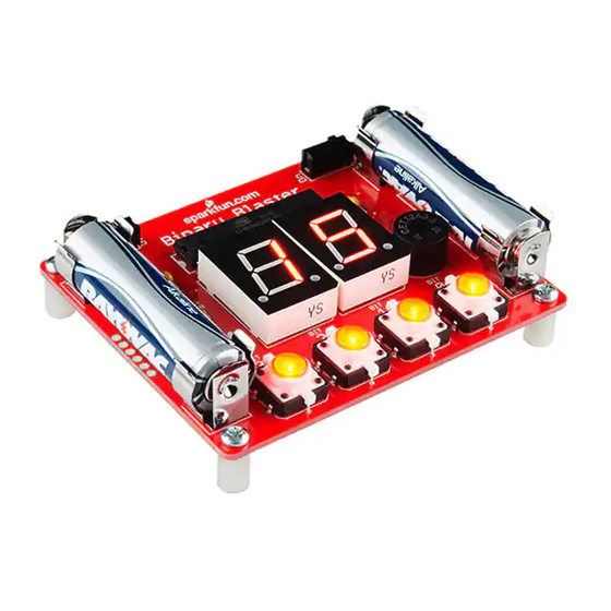
The assembled Binary Blaster PTH Kit
Necessary tools and supplies
• Soldering Iron
• Solder
• Cutters
Suggested additional tools and supplies
• Safety Glasses
• Flux Pen
• Solder Wick
• Scrubbing brush (an old toothbrush works fine)
• Dionized water for cleaning (or you can get away with tap water)
Page 1 of 15
Advertisement

Related Manuals for sparkfun Binary Blaster Series


Summary of Contents for sparkfun Binary Blaster Series
- Page 1 Page 1 of 15 Binary Blaster Assembly Guide Introduction Binary Blaster is a game that helps teach the player how to count in binary as well as convert from decimal (and hexadecimal) to binary and back, quickly. It displays a value on the 7 segment display, and the player is challenged to press the buttons in a way that represents the binary equivalent.
- Page 2 • Decoding Resistor Markings • Diode and LED Polarity • Electronics Assembly - Washing • Video - SparkFun Infrared Sensor Overview QuickStart - Your First Component Locate the 10KΩ Resistor. It has a specific pattern of stripes on it: BROWN, BLACK, ORANGE, GOLD.
- Page 3 Page 3 of 15 Push the resistor in so it is nearly flush with the board. Slightly bend the legs outward to hold it in place. Flip the board over. Hold the soldering iron’s “Sweet Spot” so it touches both the leg and the metal ring. Hold for 2 seconds. Feed solder into the joint.
- Page 4 Page 4 of 15 Second, pull away the iron. Your solder joints should look like this: Clip off any excess legs. Capacitors Locate the two 0.1uF capacitors. These look a little different than resistors. They have two leads than come down off the bottom of the component, and they have the markings “104”...
- Page 5 Page 5 of 15 Locate their positions on the PCB: Ensure that they are flush with the surface of the PCB and standing upright. Solder them into place and clip access lead length. When you’re done soldering these into place, your board should look like this: The Microcontroller Locate the microcontroller.
- Page 6 Page 6 of 15 Taking care to align the notch properly, place the ATmega328 into the PCB. While soldering the first leg (it can be any leg you choose), make sure to keep the component flush with the PCB. When you’re done soldering this component, the bottom of your board should look like this - a nice row of even volcanos: Buzzer and Switches Locate the buzzer and slide switches:...
- Page 7 Page 7 of 15 Place your components in the PCB. Flip it over, and solder them into place. When you are done, you’re PCB should look like this: Light-up Buttons Locate the 4 LED tactile buttons: These buttons are polarized. Notice the small “+” sign on the top side of the white plastic leg: Locate the 4 positions on the PCB:...
- Page 8 Page 8 of 15 Note the polarity markings on the PCB. Make sure the “+” side on the button aligns with the “+” marking on the PCB: Solder into place. When you are done, your board should look like this: 7-segment Displays Locate the 2 7-Segment Displays: These displays are polarized.
- Page 9 Page 9 of 15 Locate the 2 positions on the PCB: Note the polarity markings on the PCB. Make sure the decimal dots on the displays align with the decimal markings on the PCB. Solder into place. When you are done, your board should look like this: Battery Clips Locate the 4 Battery Clips: Locate the 4 positions on the PCB:...
- Page 10 Page 10 of 15 Note, these parts are polarized and must be soldered in so the back sides are facing out. If placed incorrectly, the batteries will not fit. Ensure they are flush and that the back sides are facing out: Solder into place.
- Page 11 Page 11 of 15 Batteries Locate the two AA batteries: These are polarized, so make sure to align the “+” and “-” sides correctly: Place the batteries into the clips, and turn it on to check that they are in correctly.
- Page 12 Page 12 of 15 every time. You must now press the binary equivalent on the four buttons. Here is a chart to help you get started: “1” = 0001 “2” = 0010 “3” = 0011 “4” = 0100 “5” = 0101 “6”...
- Page 13 We hope you enjoy your Binary Blaster. After a bit of practice, please feel free to post your best score in the discussion area of this tutorial. Thanks for your support of SparkFun and have fun blasting binary values! Troubleshooting Buttons Is one of your buttons not lighting up? Don’t fret, there is an easy way to fix...
- Page 14 Page 14 of 15 Each jumper has a small trace connecting the middle pad to the default polarity setting. The small trace is sometimes difficult to see, but it is a thin stripe of metal that should show up as a lighter color red. Using a hobby knife (aka x-acto knife), cut the default traces: Using your soldering iron, close a jumper between the middle pad and the other outside pad:...
- Page 15 SparkFun website. If you’re interested to learn more about writing code, a good place to start is by completing the example circuits in the SparkFun Inventors Kit. The microcontroller included with your Binary Blaster is actually re- programable with Arduino. This is the same microcontroller that is used in the RedBoard SIK.
Need help?
Do you have a question about the Binary Blaster Series and is the answer not in the manual?
Questions and answers