Table of Contents
Advertisement
Quick Links
Page 1 of 17
Ardumoto Kit Hookup Guide
Introduction
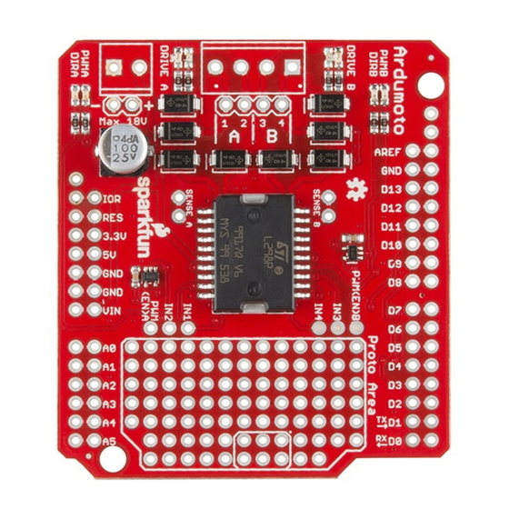
The Ardumoto Shield is a dual-motor controller for Arduino. Combined with
an Arduino, the Ardumoto makes a fantastic controller platform for RC
vehicles or even small autonomous robots. It's now easier to use, featuring
control signal LEDs, while also being much more flexible for advanced
users.
Ardumoto Shield assembled and situated on a RedBoard.
We sell the Ardumoto Shield either alone or with a set of motors and
wheels in our Ardumoto Shield Kit. This kit includes the shield as well as
pairs of tires, motors and connectors. And, of course, it's all stuffed in a
classic SparkFun red box (which may come in handy as a robot chassis).
Contents of the Ardumoto Shield Kit.
Covered in This Tutorial
This tutorial covers assembly and use of both the Ardumoto Shield and the
Ardumoto Shield Kit. Digging deeper, we'll get into some assembly tips and
an example Arduino sketch. We will also present some additional resources
that can help you get the most out of your board.
Advertisement
Table of Contents

Subscribe to Our Youtube Channel
Related Manuals for sparkfun Ardumoto Kit


Summary of Contents for sparkfun Ardumoto Kit
- Page 1 Ardumoto Shield Kit. This kit includes the shield as well as pairs of tires, motors and connectors. And, of course, it’s all stuffed in a classic SparkFun red box (which may come in handy as a robot chassis). Contents of the Ardumoto Shield Kit.
-
Page 2: Required Tools And Materials
SparkFun RedBoard - Programmed with Arduino DE V- 11021 DEV- 13975 SparkFun Ardumoto Shield SparkFun Ardumoto - Motor Driver Shield KIT-14180 DEV- 14129 Equipping the Ardumoto Shield (Non-Kit Version) If all you have is the shield, you will also probably want a couple of DC motors to drive. -
Page 3: Suggested Reading
Page 3 of 17 (3) Screw Terminals 3.5mm Pitch (2-Pin) PRT-08084 Screw Terminals with 3.5mm pitch pins. Comes in 2 or 3 positions an… Hobby Gearmotor - 200 RPM (Pair) ROB-13302 These are a pair of hobby gearmotors from DAGU. These gearmotors… Powering the Shield Both the shield and the kit will require a power source. -
Page 4: The Control Signals
Page 4 of 17 • Voltage, Current, Resistance and Ohm’s Law — When we dive into the L298, it’ll be good to know the basics of voltage and current. Meet the L298 At the heart of the Ardumoto — the big, black chip right in the middle — is an L298, one of our favorite dual-channel motor drivers around. - Page 5 Page 5 of 17 That covers the basics of the L298. If you’re curious, or want to know more about the chip, checking out the datasheet is a good place to start. Ardumoto Overview Before you get your soldering iron out, or start attaching motors, it’d be best if we briefly covered the basics of the Ardumoto Shield.
-
Page 6: Motor Outputs
Page 6 of 17 DIR A A digital signal to control the rotation direction of motor A (e.g., HIGH drives current from output 4 to 3). PWM A A PWM signal to control the speed of motor B. 0=off, 255=max speed. DIR B A digital signal to control the rotation direction of motor A... -
Page 7: Supply Voltage
Page 7 of 17 There are also four red LEDs (PWMA, DIRA, PWMB, DIRB) that are wired to the control lines directly, showing what your code is doing and also if the pins are configured correctly. The control signals are connected to LEDs on this revision so you can see what your program is doing! In this photo, DIRA is illuminated (meaning the direction is reversed), and PWMA is half-illuminated, indicating that the signal is being pulse width modulated. - Page 8 Page 8 of 17 Check the voltage and current requirements of your motor before deciding how to power your Ardumoto project. These specifications vary. The 65 RPM Hobby Gearmotors, for example, have a recommended range of 3–6V, but can be safely powered at up to 9V. We recommend 9V alkaline batteries as an easy, if not very sustainable, option.
- Page 9 Page 9 of 17 Soldering in the screw terminals Solder the Arduino Headers To interface the shield with your Arduino, soldering male connectors to the 28 header pins is a must. Soldering ensures a reliable physical and electrical connection. If you’ve never soldered before, check out our through-hole soldering tutorial.
-
Page 10: Prototyping Area
Page 10 of 17 Assembled shield on a RedBoard/Arduino Prototyping Area Let’s address the elephant in the room. There’s almost half a shield that we’ve failed to talk about thus far: the prototyping area! These rows and columns of 0.1"-spaced plated through-holes can be used to solder in all sorts of fun components. -
Page 11: Example Code
Upcycling the SparkFun Box If you have the Ardumoto Shield Kit, you probably also have a robust, resplendently red SparkFun box. These SparkFun boxes come in handy for all sorts of projects — including robot chassis! With some measured hobby knife incisions, you can cut out some mounts for the motors and tie your Arduino/shield combo down as well: This shape of robot relies mostly on balance, and slides across the floor. - Page 12 Page 12 of 17 /* Ardumoto Example Sketch by: Jim Lindblom date: November 8, 2013 license: Public domain. Please use, reuse, and modify this sketch! Adapted to v20 hardware by: Marshall Taylor date: March 31, 2017 Three useful functions are defined: setupArdumoto() Setup the Ardumoto Shield pins driveArdumoto([motor], [direction], [speed]) Drive [mot or] (0 for A, 1 for B) in [direction] (0 or 1) at a [speed] between 0 and 255. It will spin until told to stop. stopArdumoto([motor]) Stop driving [motor] (0 or 1). setupArdumoto() is called in the setup(). The loop() demonstrates use of the motor driving functions. // Clockwise and counterclockwise definitions. // Depending on how you wired your motors, you may need to swa #define FORWARD 0 #define REVERSE 1 // Motor definitions to make life easier: #define MOTOR_A 0 #define MOTOR_B 1 // Pin Assignments // //Default pins: #define DIRA 2 // Direction control for motor A #define PWMA 3 // PWM control (speed) for motor A #define DIRB 4 // Direction control for motor B #define PWMB 11 // PWM control (speed) for motor B ////Alternate pins: //#define DIRA 8 // Direction control for motor A //#define PWMA 9 // PWM control (speed) for motor A //#define DIRB 7 // Direction control for motor B //#define PWMB 10 // PWM control (speed) for motor B void setup() { ...
- Page 13 Page 13 of 17 driveArdumoto(MOTOR_B, REVERSE, 255); // Set motor B to REVE RSE at max delay(1000); // Motor B will spin as set for 1 second driveArdumoto(MOTOR_B, FORWARD, 127); // Set motor B to FOR WARD at half delay(1000); // Motor B will keep trucking for 1 second stopArdumoto(MOTOR_B); // STOP motor B // Drive both driveArdumoto(MOTOR_A, FORWARD, 255); // Motor A at max spe driveArdumoto(MOTOR_B, FORWARD, 255); // Motor B at max spe delay(1000); // Drive forward for a second // Now go backwards at half that speed: driveArdumoto(MOTOR_A, REVERSE, 127); // Motor A at max spe driveArdumoto(MOTOR_B, REVERSE, 127); // Motor B at max spe delay(1000); // Drive forward for a second // Now spin in place! driveArdumoto(MOTOR_A, FORWARD, 255); // Motor A at max spe driveArdumoto(MOTOR_B, REVERSE, 255); // Motor B at max spe delay(2000); // Drive forward for a second stopArdumoto(MOTOR_A); // STOP motor A stopArdumoto(MOTOR_B); // STOP motor B } // driveArdumoto drives 'motor' in 'dir' direction at 'spd' sp void driveArdumoto(byte motor, byte dir, byte spd) { if (motor == MOTOR_A) { digitalWrite(DIRA, dir); analogWrite(PWMA, spd); } else if (motor == MOTOR_B) { ...
- Page 14 Page 14 of 17 digitalWrite(PWMB, LOW); digitalWrite(DIRA, LOW); digitalWrite(DIRB, LOW); } Then upload to your Arduino and watch your motors spin! If you want to dig really deep into the sketch, check out the comments. Explaining the Sketch For each motor there are two mechanisms we can control — the direction of rotation and the speed.
- Page 15 Page 15 of 17 The Ardumoto has been designed primarily to be a motor driver, but we’ve taken extra time to make sure the L298 IC can be fully controlled, given the user understands the way it works. The datasheet contains a schematic diagram of the internal functions of the IC, which is the first thing to look at and contemplate before trying to do wacky things with your Ardumoto.
-
Page 16: Going Further
Page 16 of 17 The bottom side of the Ardumoto and jumpers The A/B Isolate jumpers and the A/B inputs work together. If the ‘ISOLATE’ jumpers are all opened, and the ‘SELECT’ pins are all opened, the inputs to the L298 are not connected to anything but the six input pins by the proto area. - Page 17 DC motor driver. Assembly Guide for RedBot with Shadow Chassis Assembly Guide for the RedBot Kit. This tutorial includes extra parts to follow to go along with the RedBot Inventor's Kit tutorial. https://learn.sparkfun.com/tutorials/ardumoto-kit-hookup-guide?_ga=1.258788746.106461... 4/18/2017...
Need help?
Do you have a question about the Ardumoto Kit and is the answer not in the manual?
Questions and answers