Advertisement
Quick Links
Experiment Guide for the SparkFun Tinker Kit
Introduction to the SparkFun Tinker Kit
This SparkFun Tinker Kit Experiment Guide is your map for navigating the
waters of beginning embedded electronics, robotics and citizen science
using the SparkFun RedBoard while sticking to a strict budget. This guide
contains all the information you will need to explore the 11 circuits of the
SparkFun Tinker Kit. At the center of this guide is one core philosophy –
that anyone can (and should) play around with cutting-edge electronics in a
fun and playful way while not breaking the bank.
When you're done with this guide, you'll have the know-how to start
creating your own projects and experiments. From building robots and
game controllers to data logging, the world will be your oyster. Now enough
talking – let's start tinkering!
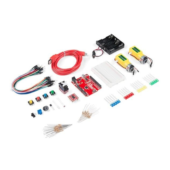
Included Materials
Here are all of the parts in the SparkFun Tinker Kit:
• SparkFun RedBoard – Our tried and true version of the Arduino
UNO.
• Breadboard – Excellent for making circuits and connections off the
Arduino.
• SparkFun Mini Screwdriver – To help you screw your RedBoard
onto the holder.
• Hobby Gearmotor Set – A set of hobby level motors with gearboxes
set to 120 RPM.
• Small Servo – Here is a simple, low-cost, high-quality servo for all
your mechatronic needs.
Page 1 of 63
Advertisement

Related Manuals for sparkfun Tinker Kit


Summary of Contents for sparkfun Tinker Kit
- Page 1 11 circuits of the SparkFun Tinker Kit. At the center of this guide is one core philosophy – that anyone can (and should) play around with cutting-edge electronics in a fun and playful way while not breaking the bank.
-
Page 2: Suggested Reading
Sorry! Batteries not included. Experiment List The following is a list of the experiements you will complete using this Tinker Kit Experiment Guide. Alternatively, you can navigate around using the buttons on the right. • Experiment 1: Blinking an LED •... - Page 3 Page 3 of 63 At SparkFun, our engineers and educators have been improving this kit and coming up with new experiments for a long time. We would like to give attribution to Oomlout, since we originally started working off the Arduino Kit material many years ago.
- Page 4 Page 4 of 63 The installation procedure is fairly straightforward, but it varies by OS. Here are some tips to help you along. We’ve also written a separate Installing Arduino tutorial if you get really stuck. Windows Install Tips The Windows version of Arduino is offered in two options: an installer or a zip file.
-
Page 5: Windows Driver Installation
Parts Needed You will need the following parts: • 1x Breadboard • 1x SparkFun RedBoard • 1x LED... - Page 6 Page 6 of 63 • 1x 330Ω Resistor • 3x Jumper Wires Didn’t Get the Tinker Kit? If you are conducting this experiment and didn’t get the Tinker Kit, we suggest using these parts: SparkFun RedBoard - Breadboard - Self-Adhesive...
-
Page 7: Hardware Hookup
Page 7 of 63 A Light-Emitting Diode (LED) will only let current through it in one direction. Think of an LED as a one-way street. When current flows through the LED, it lights up! When you are looking at the LED, you will notice that its legs are different lengths. - Page 8 “Tinker Kit Guide Code” you downloaded and placed into your “Examples” folder earlier. To open the code go to: File > Examples > Tinker Kit Guide Code > Circuit_01 You can also copy and paste the following code into the Arduino IDE. Hit...
- Page 9 BLINKING AN LED Turn an LED on for one second, off for one second, and repeat forever. This sketch was written by SparkFun Electronics, with lots of help from the Arduino community. This code is completely free for any use.
-
Page 10: Troubleshooting
• 1x 330Ω Resistor • 7x Jumper Wires • 1x Potentiometer Didn’t Get the Tinker Kit? If you are conducting this experiment and didn’t get the Tinker Kit, we suggest using these parts: SparkFun RedBoard - Breadboard - Self-Adhesive Programmed with Arduino (White) ... - Page 11 Page 11 of 63 Trimpot 10K with Knob Jumper Wires - Connected 6" (M/M, 20 pack) COM- 09806 PRT-12 795 LED - Basic Red 5mm Resistor 330 Ohm 1/6 Watt PTH - 20 pack COM- 09590 COM- 11507 Suggested Reading Before continuing with this experiment, we recommend you be familiar with the concepts in the following tutorial:...
- Page 12 “Tinker Kit Guide Code” you downloaded and placed into your “Examples” folder earlier. To open the code go to: File > Examples > Tinker Kit Guide Code > Circuit_02 Copy and paste the following code into the Arduino IDE. Hit upload, and...
- Page 13 Page 13 of 63 /* SparkFun Tinker Kit Example sketch 02 POTENTIOMETER Measure the position of a potentiometer and use it to control the blink rate of an LED. Turn the knob to make it blink faster or slower! This sketch was written by SparkFun Electronics, with lots of help from the Arduino community. This code is completely free for any use. Visit http://learn.sparkfun.com/products/2 for SIK informatio n. Visit http://www.arduino.cc to learn about Arduino. //Create global variables (variables that can be used anywher e in our sketch) // Here we're creating a variable called "sensorPin" of type "int" // and initializing it to have the value "0," which is the ana log input pin the pot is //conected to. int sensorPin = 0; // Variable for storing the pin number that the LED is connect ed to int ledPin = 13; // this function runs once when the sketch starts up void setup() { //set ledPin (13) as an OUTPUT pinMode(ledPin, OUTPUT); } // this function runs repeatedly after setup() finishes void loop() ...
- Page 14 Page 14 of 63 //loop back to the top } Code to Note int sensorValue; A “variable” is a placeholder for values that may change in your code. You must introduce, or “declare,” variables before you use them; here you are declaring a variable called sensorValue, of type “int” (integer). Don’t forget that variable names are case sensitive! sensorValue = analogRead(sensorPin);...
- Page 15 • 1x Common Cathode RGB LED • 3x 330Ω Resistors • 6x Jumper Wires Didn’t Get the Tinker Kit? If you are conducting this experiment and didn’t get the Tinker Kit, we suggest using these parts: SparkFun RedBoard - Breadboard - Self-Adhesive...
- Page 16 Page 16 of 63 Introducing the Red Green Blue (RGB) LED The Red Green Blue (RGB) LED is 3 LEDs in one. The RGB has four pins with each of the three shorter pins controlling an individual color: red, green or blue.
- Page 17 “Tinker Kit Guide Code” you downloaded and placed into your “Examples” folder earlier. To open the code go to: File > Examples >Tinker Kit Guide Code > Circuit_03 You can also copy and paste the following code into the Arduino IDE. Hit...
- Page 18 Page 18 of 63 /* SparkFun Tinker Kit Example sketch 03 RGB LED Make an RGB LED display a rainbow of colors! This sketch was written by SparkFun Electronics, with lots of help from the Arduino community. Visit http://learn.sparkfun.com/products/2 for SIK informatio n. Visit http://www.arduino.cc to learn about Arduino. //create variables for pin numbers. We are making them constan ts here, because they //never change. const int RED_PIN = 5; const int GREEN_PIN = 6; const int BLUE_PIN = 9; // How fast we plan to cycle through colors in milliseconds int DISPLAY_TIME = 10; void setup() { //set the three pin variables as outputs pinMode(RED_PIN, OUTPUT); pinMode(GREEN_PIN, OUTPUT); pinMode(BLUE_PIN, OUTPUT); } ...
- Page 19 Page 19 of 63 //wait 1 seconds delay(1000); // Green (turn just the green LED on): digitalWrite(RED_PIN, LOW); digitalWrite(GREEN_PIN, HIGH); digitalWrite(BLUE_PIN, LOW); //wait 1 second delay(1000); // Blue (turn just the blue LED on): digitalWrite(RED_PIN, LOW); digitalWrite(GREEN_PIN, LOW); digitalWrite(BLUE_PIN, HIGH); //wait 1 second delay(1000); // Yellow (turn red and green on): digitalWrite(RED_PIN, HIGH); digitalWrite(GREEN_PIN, HIGH); digitalWrite(BLUE_PIN, LOW); //wait 1 second delay(1000); // Cyan (turn green and blue on): digitalWrite(RED_PIN, LOW); digitalWrite(GREEN_PIN, HIGH); digitalWrite(BLUE_PIN, HIGH); //wait 1 second delay(1000); // Purple (turn red and blue on): digitalWrite(RED_PIN, HIGH); digitalWrite(GREEN_PIN, LOW); digitalWrite(BLUE_PIN, HIGH); //wait 1 second delay(1000); // White (turn all the LEDs on): digitalWrite(RED_PIN, HIGH); digitalWrite(GREEN_PIN, HIGH); digitalWrite(BLUE_PIN, HIGH); //wait 1 second delay(1000);...
- Page 20 • 1x Breadboard • 1x SparkFun RedBoard • 6x LEDs • 6x 330Ω Resistors • 7x Jumper Wires Didn’t Get the Tinker Kit? If you are conducting this experiment and didn’t get the Tinker Kit, we suggest using these parts:...
- Page 21 Page 21 of 63 SparkFun RedBoard - Breadboard - Self-Adhesive Programmed with Arduino (White) DE V- 12757 PRT-12 002 Jumper Wires - Connected LED - Basic Red 5mm 6" (M/M, 20 pack) COM- 09590 PRT- 12795...
- Page 22 “Tinker Kit Guide Code” you downloaded and placed into your “Examples” folder earlier. To open the code go to: File > Examples > Tinker Kit Guide Code > Circuit_04 You can also copy and paste the following code into the Arduino IDE. Hit...
- Page 23 Page 23 of 63 /* SparkFun Tinker Kit Example sketch 04 MULTIPLE LEDs Make six LEDs dance. Dance LEDs, dance! This sketch was written by SparkFun Electronics, with lots of help from the Arduino community. This code is completely free for any use. Visit http://learn.sparkfun.com/products/2 for SIK informatio n. Visit http://www.arduino.cc to learn more about Arduino. // To keep track of all the LED pins, we'll use an "array." // An array lets you store a group of variables, and refer to them // by their position, or "index." Here we're creating an arra y of // six integers, and initializing them to a set of values: int ledPins[] = {4,5,6,7,8,9}; void setup() { //create a local variable to store the index of which pin w e want to control int index; // For the for() loop below, these are the three statements: // 1. index = 0; Before starting, make index = 0. // 2. index <= 5; If index is less or equal to 5, run th e following code // 3. index++ Putting "++" after a variable means "add o ne to it". // When the test in statement 2 is finally false, the sketch // will continue. // This for() loop will make index = 0, then run the pinMode // statement within the brackets. It will then do the same t...
- Page 24 Page 24 of 63 // "//" in front of them). To try different LED displays, re move // the "//" in front of the ones you'd like to run, and add "//" // in front of those you don't to comment out (and disable) those // lines. // Light up all the LEDs in turn oneAfterAnotherNoLoop(); // Same as oneAfterAnotherNoLoop, but less typing //oneAfterAnotherLoop(); // Turn on one LED at a time, scrolling down the line //oneOnAtATime(); // Light the LEDs middle to the edge s //pingPong(); // Chase lights like you see on signs //marquee(); // Blink LEDs randomly //randomLED(); } /* oneAfterAnotherNoLoop() This function will light one LED, delay for delayTime, then li ght the next LED, and repeat until all the LEDs are on. It will th en turn them off in the reverse order. void oneAfterAnotherNoLoop() { // time (milliseconds) to pause between LEDs int delayTime = 100; // turn all the LEDs on: digitalWrite(ledPins[0], HIGH); //Turns on LED #0 (pin 4) delay(delayTime); //wait delayTime millisecon digitalWrite(ledPins[1], HIGH); //Turns on LED #1 (pin 5)
- Page 25 Page 25 of 63 // turn all the LEDs off: digitalWrite(ledPins[5], LOW); //Turn off LED #5 (pin 9) delay(delayTime); //wait delayTime millisecon digitalWrite(ledPins[4], LOW); //Turn off LED #4 (pin 8) delay(delayTime); //wait delayTime millisecon digitalWrite(ledPins[3], LOW); //Turn off LED #3 (pin 7) delay(delayTime); //wait delayTime millisecon digitalWrite(ledPins[2], LOW); //Turn off LED #2 (pin 6) delay(delayTime); //wait delayTime millisecon digitalWrite(ledPins[1], LOW); //Turn off LED #1 (pin 5) delay(delayTime); //wait delayTime millisecon digitalWrite(ledPins[0], LOW); //Turn off LED #0 (pin 4) delay(delayTime); //wait delayTime millisecon ds } /* oneAfterAnotherLoop() This function does exactly the same thing as oneAfterAnotherNo Loop(), but it takes advantage of for() loops and the array to do it w ith much less typing. void oneAfterAnotherLoop() { int index; int delayTime = 100; // milliseconds to pause between LEDs // make this smaller for faster switchi // Turn all the LEDs on: // This for() loop will step index from 0 to 5 // (putting "++" after a variable means add one to it) // and will then use digitalWrite() to turn that LED on. for(index = 0; index <= 5; index++) { ...
- Page 26 Page 26 of 63 oneOnAtATime() This function will step through the LEDs, lighting only one at at time. void oneOnAtATime() int index; int delayTime = 100; // milliseconds to pause between LEDs // make this smaller for faster switchi // step through the LEDs, from 0 to 5 for(index = 0;...
- Page 27 Page 27 of 63 void marquee() int index; int delayTime = 200; // milliseconds to pause between LEDs // Make this smaller for faster switchi // Step through the first four LEDs // (We'll light up one in the lower 3 and one in the upper for(index = 0;...
- Page 28 – a push button – by using a digital input. We will use it to cycle through different colors on the RGB. Parts Needed You will need the following parts: • 1x Breadboard • 1x SparkFun RedBoard • 1x RGB LED...
- Page 29 • 8x Jumper Wires • 1x Push Button • 1x 10K Resistors Didn’t Get the Tinker Kit? If you are conducting this experiment and didn’t get the Tinker Kit, we suggest using these parts: SparkFun RedBoard - Breadboard - Self-Adhesive...
- Page 30 Page 30 of 63 Resistor 10K Ohm 1/6th Watt PTH - 20 pack COM- 11508 Suggested Reading Before continuing with this experiment, we recommend you be somewhat familiar with the concepts in these tutorials: • Switch Basics • Analog vs. Digital Introducing the Push Button A momentary push button closes or completes the circuit only while it is being pressed.
- Page 31 “Tinker Kit Guide Code” you downloaded and placed into your “Examples” folder earlier. To open the code go to: File > Examples > Tinker Kit Guide Code > Circuit_05 You can also copy and paste the following code into the Arduino IDE. Hit...
- Page 32 SparkFun Tinker Kit Example sketch 05 PUSH BUTTONS Use pushbuttons for digital input This sketch was written by SparkFun Electronics, with lots of help from the Arduino community. This code is completely free for any use. Visit http://learn.sparkfun.com/products/2 for SIK informatio Visit http://www.arduino.cc to learn about Arduino.
- Page 33 Page 33 of 63 digitalWrite(redPin,LOW); digitalWrite(greenPin,LOW); digitalWrite(bluePin,LOW); //else if counter is equal to 1, redPin is HIGH else if(counter == 1) digitalWrite(redPin,HIGH); digitalWrite(greenPin,LOW); digitalWrite(bluePin,LOW); //else if counter is equal to 2 greenPin is HIGH else if(counter ==2) digitalWrite(redPin,LOW); digitalWrite(greenPin,HIGH); digitalWrite(bluePin,LOW); //else if counter is equal to 3 bluePin is HIGH else if(counter ==3) digitalWrite(redPin,LOW);...
- Page 34 • 7x Jumper Wires • 1x Photoresistor • 1x 10K Resistor Didn’t Get the Tinker Kit? If you are conducting this experiment and didn’t get the Tinker Kit, we suggest using these parts: SparkFun RedBoard - Breadboard - Self-Adhesive Programmed with Arduino (White) ...
- Page 35 Page 35 of 63 Mini Photocell Jumper Wires - Connected 6" (M/M, 20 pack) SEN- 09088 PRT-12 795 LED - Basic Red 5mm Resistor 330 Ohm 1/6 Watt PTH - 20 pack COM- 09590 COM- 11507 Resistor 10K Ohm 1/6th Watt PTH - 20 pack ...
- Page 36 “Tinker Kit Guide Code” you downloaded and placed into your “Examples” folder earlier. To open the code go to: File > Examples > Tinker Kit Guide Code > Circuit_06 You can also copy and paste the following code into the Arduino IDE. Hit...
- Page 37 LED when it is "dark" and turn back off again whe n it is "bright." This sketch was written by SparkFun Electronics, with lots of help from the Arduino community. This code is completely free for any use.
- Page 38 Page 38 of 63 Code to Note lightCal is a calibration variable. lightCal = analogRead(sensorPin); Your RedBoard takes a single reading of the light sensor in the setup and uses this value to compare against the lightVal in the loop. This value doesn’t change in the loop, as it is set in the setup function.
-
Page 39: Temperature Sensor
• 1x SparkFun RedBoard • 3x Jumper Wires • 1x TMP36 Temperature Sensor Didn’t Get the Tinker Kit? If you are conducting this experiment and didn’t get the Tinker Kit, we suggest using these parts: SparkFun RedBoard - Breadboard - Self-Adhesive... - Page 40 “Tinker Kit Guide Code” you downloaded and placed into your “Examples” folder earlier. To open the code go to: File > Examples > Tinker Kit Guide Code > Circuit_07 You can also copy and paste the following code into the Arduino IDE. Hit...
- Page 41 Example sketch 07 TEMPERATURE SENSOR Use the "serial monitor" window to read a temperature senso This sketch was written by SparkFun Electronics, with lots of help from the Arduino community. This code is completely free for any use. Visit http://learn.sparkfun.com/products/2 for SIK informatio Visit http://www.arduino.cc to learn more about Arduino.
- Page 42 Page 42 of 63 tempC = (volts 0.5) * 100 ; // print the celcius temperature over the serial port Serial.print(" degrees C: "); Serial.print(tempC); //print spacer Serial.print(" **** "); // Convert from celcius to fahrenheit tempF = (tempC * 9.0 / 5.0) + 32.0; //print the fahrenheit temperature over the serial port Serial.print("...
-
Page 43: Parts Needed
You will need the following parts: • 1x Breadboard • 1x SparkFun RedBoard • 1x Servo • 3x Jumper Wires Didn’t Get the Tinker Kit? If you are conducting this experiment and didn’t get the Tinker Kit, we suggest using these parts:... - Page 44 Page 44 of 63 SparkFun RedBoard - Breadboard - Self-Adhesive Programmed with Arduino (White) DE V- 12757 PRT-12 002 Servo - Generic (Sub-Micro Jumper Wires - Connected Size) 6" (M/M, 20 pack) ROB- 09065 PRT-12 795...
- Page 45 “Tinker Kit Guide Code” you downloaded and placed into your “Examples” folder earlier. To open the code go to: File > Examples > Tinker Kit Guide Code > Circuit_08 You can also copy and paste the following code into the Arduino IDE. Hit...
- Page 46 Example sketch 08 SINGLE SERVO Sweep a servo back and forth through its full range of motio This sketch was written by SparkFun Electronics, with lots of help from the Arduino community. This code is completely free for any use.
- Page 47 Page 47 of 63 // Move to next position servo1.write(position); // Short pause to allow it to move delay(20); // Tell servo to go to 0 degrees, stepping by one degree for(position = 180; position >= 0; position = 1) // Move to next position servo1.write(position);...
- Page 48 • 1x SN754410 H-Bridge IC • 1x 48:1 Geared Motor • 12x Jumper Wires Didn’t Get the Tinker Kit? If you are conducting this experiment and didn’t get the Tinker Kit, we suggest using these parts: SparkFun RedBoard - Breadboard - Self-Adhesive...
- Page 49 Page 49 of 63 H-Bridge Motor Driver 1A COM- 00315 Suggested Reading Before continuing with this experiment, we recommend you be familiar with the concepts in the following tutorial: • Bildr Tutorial Introducing the H-Bridge The SN754410 is an Integrated Circuit (IC), called an H-Bridge, that makes controlling motors easier.
- Page 50 Page 50 of 63 You can control up to two motors with a single IC. You can use this diagram as a reference for pin numbers in conjunction with the table below. Image courtesy of ITP at NYU Hookup Table PWM signal for controlling the speed of motor A Direction pin 1 for motor A Motor A connection 1...
- Page 51 “Tinker Kit Guide Code” you downloaded and placed into your “Examples” folder earlier. To open the code go to: File > Examples > Tinker Kit Guide Code > Circuit_09 You can also copy and paste the following code into the Arduino IDE. Hit...
- Page 52 Page 52 of 63 SparkFun Tinker Kit Example sketch 9 SparkFun Motor Driver Use the SparkFun Motor Driver to control the speed and directi on of a motor This sketch was written by SparkFun Electronics, with lots of help from the Arduino community.
- Page 53 Page 53 of 63 analogWrite(PWM, 0); //wait 1 second delay(1000); Code to Note language:cpp digitalWrite(DIR_A, HIGH); digitalWrite(DIR_B, LOW); analogWrite(PWM, 255); The Motor Driver uses a control logic that works by pulling certain pins HIGH or LOW (pins 4 and 5 in this case) to change the direction of the motor’s rotation and then send a PWM signal to pin 6 to control the speed.
- Page 54 • 1x H-Bridge IC • 1x 48:1 ratio Gearmotor • 20x Jumper Wires Didn’t Get the Tinker Kit? If you are conducting this experiment and didn’t get the Tinker Kit, we suggest using these parts: SparkFun RedBoard - Breadboard - Self-Adhesive...
- Page 55 Page 55 of 63 Jumper Wires - Connected Hobby Gearmotor - 200 6" (M/M, 20 pack) RPM (Pair) PRT- 12795 ROB- 13302 H-Bridge Motor Driver 1A COM- 00315 Hardware Hookup Ready to start hooking everything up? Check out the wiring diagram below to see how everything is connected.
- Page 56 “Tinker Kit Guide Code” you downloaded and placed into your “Examples” folder earlier. To open the code go to: File > Examples > Tinker Kit Guide Code > Circuit_10 You can also copy and paste the following code into the Arduino IDE. Hit...
- Page 57 HBridge Motor Controller with Inputs Use the inputs to manually set the direction and speed of a motor. This sketch was written by SparkFun Electronics, with lots of help from the Arduino community. This code is completely free for any use.
- Page 58 Page 58 of 63 //motor contoller direction pins set to forward digitalWrite(DIR_A, HIGH); digitalWrite(DIR_B, LOW); //write the speed by using the parameter of spd analogWrite(PWM, spd); //create a custom function that defines moving in reverse //the reverse() function accepts one parameter and that is //the speed at which you want to drive in reverse (0255) void reverse(int spd) //set motor controller pins to reverse...
- Page 59 • 1x Common Cathode RGB LED • 3x 330Ω Resistors • 6x Jumper Wires Didn’t Get the Tinker Kit? If you are conducting this experiment and didn’t get the Tinker Kit, we suggest using these parts: SparkFun RedBoard - Breadboard - Self-Adhesive...
- Page 60 “Tinker Kit Guide Code” you downloaded and placed into your “Examples” folder earlier. To open the code go to: File > Examples >Tinker Kit Guide Code > Circuit_03 You can also copy and paste the following code into the Arduino IDE. Hit...
- Page 61 Serial Color Mixing Read Serial data from your computer and use it to set the RGB values of the RGB LED. This sketch was written by SparkFun Electronics, with lots of help from the Arduino community. Visit http://learn.sparkfun.com/products/2 for SIK informatio Visit http://www.arduino.cc to learn about Arduino.
- Page 62 Page 62 of 63 Whether you are using serial communication as an input or an output, you need to use the method to start your serial port. The baud rate begin() can vary, but 9600 is the standard for most applications. Serial.parseInt();...
- Page 63 Page 63 of 63 • Installing Arduino • Installing an Arduino Library • Arduino Data Types For more hardware-related tutorials, give these a read: • Breadboards • Working with Wire • Sewing with Conductive Thread https://learn.sparkfun.com/tutorials/experiment-guide-for-the-sparkfun-tinker-kit/all 6/14/2016...
Need help?
Do you have a question about the Tinker Kit and is the answer not in the manual?
Questions and answers