Advertisement
Quick Links
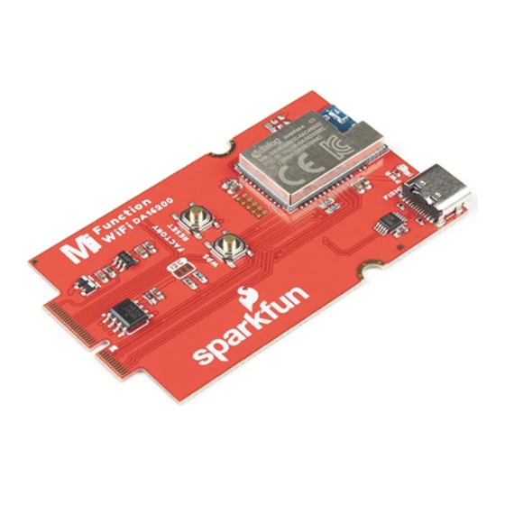
MicroMod WiFi Function Board - DA16200 Hookup Guide
Introduction
Want to add all the IoT functionality of the DA16200 to the adaptability of the MicroMod system? Then you're in
luck! The SparkFun MicroMod DA16200 Function Board adds a fully integrated WiFi module with a 40MHz crystal
oscillator, 32.768KHz RTC clock, RF Lumped RF filter, 4MB flash memory, and an on-board chip antenna to any
MicroMod project. With the addition of JTAG connectors for deep dive programming, you've got everything you
need to get your MicroMod setup ready for your next IoT project.
SparkFun MicroMod WiFi Function Board - DA16200
WRL-18594
Product Showcase: SparkFun MicroMod Main and Function Boa... ...
Product Showcase: SparkFun MicroMod Main and Function Boa
N
O
T
O
U
C
C
A
R
U
Y
I
G
L
N
O
R
T
E
S
I
G
E
R
Advertisement

Related Manuals for sparkfun DA16200


Summary of Contents for sparkfun DA16200
- Page 1 MicroMod WiFi Function Board - DA16200 Hookup Guide Introduction Want to add all the IoT functionality of the DA16200 to the adaptability of the MicroMod system? Then you're in luck! The SparkFun MicroMod DA16200 Function Board adds a fully integrated WiFi module with a 40MHz crystal oscillator, 32.768KHz RTC clock, RF Lumped RF filter, 4MB flash memory, and an on-board chip antenna to any...
- Page 2 To follow along with this tutorial, you will need the following materials at a minimum. You may not need everything though depending on what you have. Add it to your cart, read through the guide, and adjust the cart as necessary. SparkFun MicroMod Main Board - Single Reversible USB A to C Cable - 2m ...
- Page 3 SparkFun MicroMod Main Board - Single SparkFun MicroMod Main Board - Double DEV-18575 DEV-18576 MicroMod Processor Board There are a variety of MicroMod Processor Boards available to choose from. SparkFun MicroMod Teensy Processor SparkFun MicroMod ESP32 Processor DEV-16402 ...
-
Page 4: Hardware Overview
Hardware Overview DA16200 The MicroMod WiFi Function Board includes the DA16200 module from Dialog with AT command firmware. This chip is a fully integrated Wi-Fi® module with ultra-low power consumption, 40 MHz crystal oscillator, 32.768 KHz RTC clock, RF Lumped RF filter, 4 M-byte flash memory, and an onboard chip antenna. For more information,... - Page 5 Power To power the board, you will need to apply power to a SparkFun Main Board; either a Single or a Double. Power applied will connect to the Function Board's VIN pin, which will be regulated down for the rest of the board with the AP2112 3.3V/600mA voltage regulator.
- Page 6 Reset Button The reset button allows users to reset the program running on the Artemis module without unplugging the board. WPS Button The Wi-Fi Protected Setup Button allows you to easily and quickly connect to a WiFi network. EEPROM The board includes an I C EEPROM. To enable writing to the EEPROM, pull WP low, either through the EEPROM_WP pin or by closing JP3.
- Page 7 There is only one LED available which is the Power LED. The LED lights up to indicate availability for the DA16200 from the 3.3V voltage regulator. You can disable it by cutting the jumper on the back of the board (see Jumpers below).
- Page 8 WP - By default, write protect for the EEPROM is on. To disable write protection, close this jumper. Hardware Pinout The M.2 connector on the MicroMod WiFi Function Board - DA16200 is routed according to the pinout chart below:...
- Page 9 Note that the M.2 connector pins on opposing sides are offset from each other as indicated by the bottom pins where it says (Not Connected)*. There is no connection to pins that have a "-" under the primary function. MICROMOD WIFI FUNCTION BOARD - DA16200 PINOUT TABLE AUDIO UART...
- Page 10 The RTC block detects an external event signal via this pin and wakes up DA16200 from Sleep mode 2 or Sleep mode 3. RTC_WAKE2 This pin is an input pin for receiving an...
- Page 11 Controls the write EEPROM_WP protection pin for the EEPROM. Pull low to enable. Controls EEPROM's EEPROM_A0 I C address configuration. Controls EEPROM's EEPROM_A1 I C address configuration. Controls EEPROM's EEPROM_A2 Module Key I C address configuration. Module Key Module Key Module Key Module Key Module Key...
-
Page 12: Hardware Hookup
Board Dimensions The board uses the standard MicroMod Function Board size which measures about 1.50"x2.56". Hardware Hookup Adding a Processor Board to the Main Board Align the top key of the MicroMod Artemis Processor Board to the Processor screw terminal of your Main Board and angle the board into the socket. - Page 13 Adding a Function Board to the Main Board As with the Processor Board, align the top key of the MicroMod WiFi Function Board to the screw terminal of your Main Board on the Function Board side and angle the board into the socket. Insert the board at an angle into the M.2 connector.
-
Page 14: Software Installation
DA16200 Firmware Update To update the firmware you will need to connect the USB C cable to the MicroMod WiFi Function Board (DA16200) to a computer's COM port. An additional Main Board with a second USB C cable is also needed to power the Main Board and MicroMod WiFi Function Board. - Page 15 "x86" for 32-bit processors or "x64" for 64-bit processors. Main Board Example - Pin Connection Table For the following examples, we are using the Artemis Processor Board. For DA16200 specific pins, here is the mapping to use in Arduino sketches:...
- Page 16 Example 1: Basic Connection Copy and paste the code below into a fresh Arduino sketch.
- Page 17 Hardware Platform: MicroMod Artemis Processor, Single MicroMod Main Board Hardware Connections: Connect the MicroMod Processor Board to the Processor M2 Connector of the Main Board Connect the MicroMod DA16200 Function Board to the Function M2 Connector of the Main Board --> RTC_PWR_KEY --> PWR_EN 3.3V...
- Page 18 Serial.println("Failed to receive initialization message\n"); Serial.println("Make sure the baud rate for Serial1 matches the baud rate\n" \ "saved to the DA16200. You can also perform a factory reset by\n" \ "pressing and holding the GPIOA7 button for ~5s, which will\n" \ "reset the baud rate back to 115200");...
- Page 19 Serial1.print(char(Serial.read())); while(Serial1.available()) Serial.print(char(Serial1.read())); Set your Board and Serial Port, and then upload the sketch to your Arduino. Then open the serial monitor. Make sure your baud rate is set to 9600. You'll begin to see output. Example 2: Connecting to WiFi Let's check out the WiFi with a simple example to grab the time.
- Page 20 Hardware Platform: MicroMod Artemis Processor, Single MicroMod Main Board Hardware Connections: Connect the MicroMod Processor Board to the Processor M2 Connector of the Main Board Connect the MicroMod DA16200 Function Board to the Function M2 Connector of the Main Board --> RTC_PWR_KEY --> PWR_EN 3.3V...
- Page 21 String msg = ""; while(count<20) while(Serial1.available()) msg += char(Serial1.read()); if(msg.length() > 5) break; count++; delay(100); msg = msg.substring(3,msg.length()); //Remove NULL,CR,LF characters from response if(msg.length()>5) Serial.println("Expecting: \"INIT:DONE,(0 or 1)"); Serial.println("Received: " + msg); else Serial.println("Failed to receive initialization message.\n" \ "Make sure you're using the correct baud rate.\n"); while(1);...
- Page 22 Serial.print(msg); if(msg.length() > 1) break; //Listen for ready message ("+INIT:DONE") after the reset is finished count = 0; msg = ""; while(count<20) while(Serial1.available()) msg += char(Serial1.read()); if(msg.length() > 5) break; count++; delay(100); Serial.println(count); Serial.println(msg); msg = msg.substring(3,msg.length()); //Remove NULL,CR,LF characters from response if(msg.length()>5) Serial.println("Expecting: \"INIT:DONE,(0 or 1)");...
- Page 23 msg = msg.substring(3,msg.length()); //Remove NULL,CR,LF characters from response //If connection to AP is successful, response will be WFJAP:1,SSID,IP_ADDRESS, or WJAP:0 if fa iled if(msg.startsWith("WFJAP:1")) //Talk to NTP server to get the current time, along with how often to get time sync Serial.println("Sending:AT+NWSNTP=1,pool.ntp.org,86400");...
-
Page 24: Firmware Update
SPARKFUN TECHNICAL ASSISTANCE PAGE If you don't find what you need there, the SparkFun Forums: MicroMod are a great place to find and ask for help. If this is your first visit, you'll need to create a Forum Account to search product forums and post questions. - Page 25 MicroMod Asset Tracker Carrier Board Hookup Board Hookup Guide Guide A short Hookup Guide to get started with the SparkFun Get started with the SparkFun MicroMod Asset Tracker MicroMod Input and Display Carrier Board Carrier Board following this Hookup Guide. The Asset...
Need help?
Do you have a question about the DA16200 and is the answer not in the manual?
Questions and answers