Table of Contents
Advertisement
Quick Links
SparkFun Qwiic GPIO Hookup Guide
Introduction
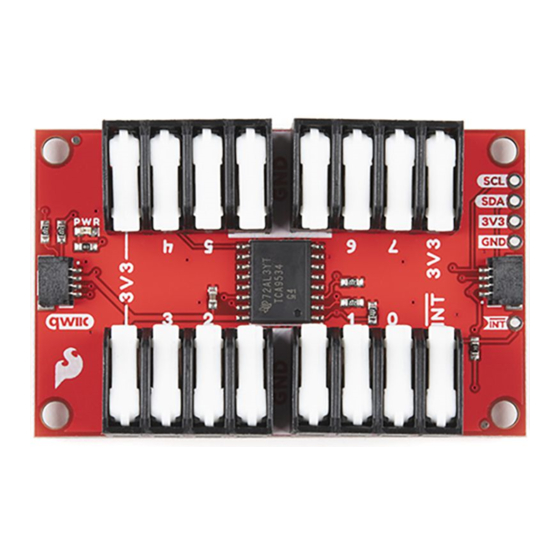
The SparkFun Qwiic GPIO is an I C device aimed at simplifying adding extra GPIO pins to a microcontroller. The
board uses the TCA9534U I/O Expander IC from Texas Instruments to add up to 8 digital inputs and outputs
2
controlled via an I C interface. The TCA9534U features three address select pins that can be set to configure eight
unique addresses meaning you can have up to 64 I/O pins controlled from a single I C bus!
SparkFun Qwiic GPIO
DEV-17047
Product Showcase: SparkFun Qwiic GPIO
Product Showcase: SparkFun Qwiic GPIO
2
2
Advertisement
Table of Contents

Subscribe to Our Youtube Channel
Related Manuals for sparkfun Qwiic GPIO


Summary of Contents for sparkfun Qwiic GPIO
- Page 1 Introduction The SparkFun Qwiic GPIO is an I C device aimed at simplifying adding extra GPIO pins to a microcontroller. The board uses the TCA9534U I/O Expander IC from Texas Instruments to add up to 8 digital inputs and outputs controlled via an I C interface.
-
Page 2: Required Materials
Library and a Python Package for the Qwiic GPIO to make writing code for it as easy as possible. In this guide we'll go over everything you need to know about the Qwiic GPIO so you can add those extra I/O pins... - Page 3 SparkFun Qwiic Shield for Thing Plus SparkFun Qwiic Shield for Arduino DEV-16790 DEV-14352 SparkFun Qwiic Adapter SparkFun Qwiic Shield for Arduino Nano DEV-14495 DEV-16789 Finally, you'll need at least one Qwiic cable and possibly some hook up wire or jumper cables. Below are a few options for each of those cable types: Jumper Wires Standard 7"...
- Page 4 Hook-Up Wire - Assortment (Stranded, 22 Qwiic Cable - 200mm AWG) PRT-14428 PRT-11375 Suggested Reading If you aren't familiar with the Qwiic system, we recommend reading here for an overview: We would also recommend taking a look at the following tutorials if you aren't familiar with the concepts covered in them: Polarity Serial Terminal Basics...
-
Page 5: Hardware Overview
Three hardware pins (A0, A1 and A2) are dedicated I C address select pins. We've added three jumpers to the Qwiic GPIO to allow users to have up to 8 boards on the same bus. The Solder Jumpers section below goes into more detail on how those pins and jumpers are used on the Qwiic GPIO. - Page 6 Each I/O pin defaults as an input at power on. Sending the appropriate commands will switch them to an output and you can also invert the polarity of each pin as well via I C. Read on to the Qwiic GPIO Arduino Library and Python package sections for more information on how to configure and interact with these pins.
-
Page 7: Power Jumper
CLICK HERE TO OPEN THE I C ADDRESS TABLE Board Dimensions The Qwiic GPIO is a bit larger than our standard Qwiic breakout size (1" x 1"). It measures in at 2.40" x 1.50" (60.96mm x 38.10mm) and has four mounting holes that fit a 4-40 screw. -
Page 8: Hardware Assembly
If you prefer to use the PTH pins broken out on the Qwiic GPIO you will need to solder to them. For a temporary connection for prototyping, these IC Hooks are a great option to make that connection. For users not familiar with... - Page 9 Having trouble seeing the detail in this mess of jumper wires? Click on the photo for a larger view! With the Qwiic GPIO circuit assembled and connected to your microcontroller it's time to get some code uploaded and start controlling the extra I/O pins via I C! Qwiic GPIO Arduino Library Note: This library assumes you are using the latest version of the Arduino IDE on your desktop.
-
Page 10: Advanced Functions
GPIO Arduino Library > Example1a-Write_GPIO. This example sets up GPIO 0 as an output and toggles it HIGH and LOW. The code starts up by initializing the Qwiic GPIO on the I C bus on the default address and sets GPIO0 as an output: myGPIO.pinMode(0, GPIO_OUT);... - Page 11 Example 1B: Write GPIO - Port This version of writing to the Qwiic GPIO controls the entire port (all eight GPIO pins). In order to set up the port we need to define the number of GPIO pins we are using as well as construct a boolean to define each pin as either an input or output.
- Page 12 With the port set up and configured, we can move on to initializing the Qwiic GPIO on the I C bus and start reading the status of the entire GPIO port. As the comment in the code below explains, in order to read from the port you can either return the full register value as an unsigned 8-bit integer or by passing an array of 8 booleans modified by the function that returns the status of each pin.
- Page 13 Example 3A: Inversion Example 3A shows how to invert the signal polarity of an input on the Qwiic GPIO. Polarity inversion only works on pins configured as an input so first we set the pin mode and then we invert the polarity. Input pins default to active HIGH so inverting it changes it to active LOW.
- Page 14 Example 3B: Inversion - Port Example 3B, as you might expect by now, exhibits how to invert the entire port on the Qwiic GPIO. The code starts as the other port examples do by defining the number of pins and setting the pin mode of all pins on the port. It then inverts half of the pins' polarity using a second boolean.
- Page 15 Now that our interrupt pin is configured the code monitors the GPIO pins' statuses and any time the status changes, the interrupt pin on the Qwiic GPIO will be driven LOW. You can view the entire loop and ISR function...
-
Page 16: Installation
This Python package has a few dependencies in the code, listed below: from __future__ import print_function import math import qwiic_i2c Function Overview For a full overview of all the functions included with the Qwiic GPIO Py package, head on over to the ReadtheDocs page. Python Examples... - Page 17 With the Qwiic GPIO Python Package installed, we can start working with the examples included with it. In this section we'll go over each example and highlight pertinent bits of code. To run the examples, download or copy the code into a file then open/save the example file (if needed) and execute the code in your preffered Python IDE.
- Page 18 Qwiic GPIO Example 1\n") myGPIO = qwiic_gpio.QwiicGPIO() if myGPIO.isConnected() == False: print("The Qwiic GPIO isn't connected to the system. Please check your connection", \ file=sys.stderr) return myGPIO.begin() myGPIO.mode_0 = myGPIO.GPIO_OUT myGPIO.mode_1 = myGPIO.GPIO_OUT myGPIO.mode_2 = myGPIO.GPIO_OUT...
- Page 19 Example 1") sys.exit(0) Qwiic GPIO Example 2 Example 2 shows how to read each I/O pin when they are configured as inputs. It first sets up all pins using the function as we did in Example 1. The code then monitors and prints out the status of each input every setMode 0.25 seconds.
- Page 20 Qwiic GPIO Example 2\n") myGPIO = qwiic_gpio.QwiicGPIO() if myGPIO.isConnected() == False: print("The Qwiic GPIO isn't connected to the system. Please check your connection", file=sys.stderr) return myGPIO.begin() myGPIO.mode_0 = myGPIO.GPIO_IN myGPIO.mode_1 = myGPIO.GPIO_IN myGPIO.mode_2 = myGPIO.GPIO_IN myGPIO.mode_3 = myGPIO.GPIO_IN...
- Page 21 Qwiic GPIO Example 3 Example 3 demonstrates how to invert an I/O pin configured as an input. We first set all eight pins as inputs and then invert half of them using the function. As we covered in the Arduino Examples section, setInversion(self) each I/O pin set as an input defaults to an active HIGH input so inverting it switches it to an active LOW input.
- Page 22 Qwiic GPIO Example 3\n") myGPIO = qwiic_gpio.QwiicGPIO() if myGPIO.isConnected() == False: print("The Qwiic GPIO isn't connected to the system. Please check your connection", file=sys.stderr) return myGPIO.begin() myGPIO.mode_0 = myGPIO.GPIO_IN myGPIO.mode_1 = myGPIO.GPIO_IN myGPIO.mode_2 = myGPIO.GPIO_IN myGPIO.mode_3 = myGPIO.GPIO_IN...
- Page 23 (KeyboardInterrupt, SystemExit) as exErr: print("\nEnding Example 1") sys.exit(0) Resources and Going Further That wraps up this Hookup Guide! For more information about the Qwiic GPIO, take a look at the following links: Schematic (PDF) Eagle Files (ZIP) Dimensional Drawing (PNG)
Need help?
Do you have a question about the Qwiic GPIO and is the answer not in the manual?
Questions and answers