Advertisement
Quick Links
Qwiic Pro Micro USB-C (ATmega32U4) Hookup Guide
Introduction
Heads up! This is for the Qwiic Pro Micro USB-C (ATmega32U4) version. If you are looking for
information about hardware on the Pro Micros with the micro-b USB connector, make sure to check out the
older Pro Micro & Fio V3 Hookup Guide.
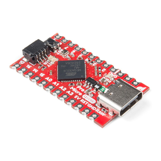
The SparkFun Qwiic Pro Micro USB C is a really cool, little development board. It's an Arduino-compatible
microcontroller, micro-sized, and it accomplishes with one single chip what old Arduino Unos, Duemilanoves, and
Diecimeillas could never dream of: true USB functionality. In this tutorial, we'll check out the updated Qwiic Pro
Micro and go through a few examples to get you started!
SparkFun Qwiic Pro Micro - USB-C (ATmega32U4)
DEV-15795
Product Showcase: SparkFun Qwiic Pro Micro
Product Showcase: SparkFun Qwiic Pro Micro
Advertisement


Need help?
Do you have a question about the Qwiic Pro Micro USB-C and is the answer not in the manual?
Questions and answers