Table of Contents
Advertisement
Quick Links
SparkFun QwiicBus Hookup Guide
Introduction
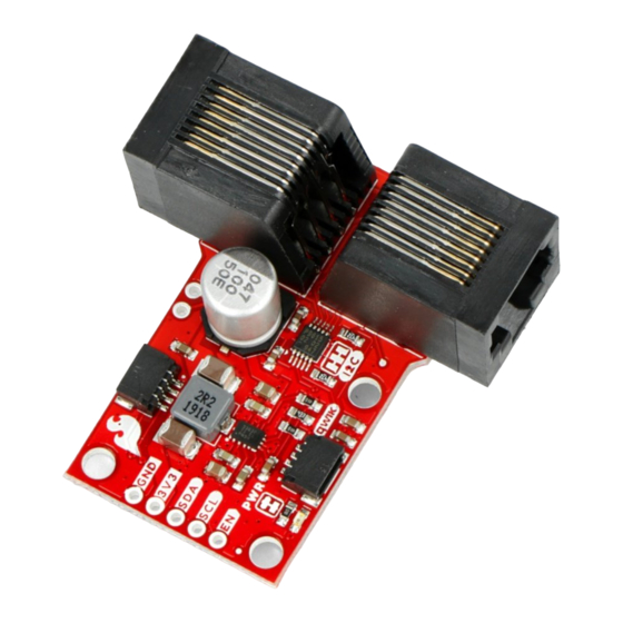
Introducing the SparkFun QwiicBus system! The QwiicBus is a fast and easy way to extend the range of your I C
bus. The QwiicBus system features two boards: the SparkFun QwiicBus EndPoint and the SparkFun QwiicBus
MidPoint. SparkFun also offers the QwiicBus Kit that includes two EndPoints, one MidPoint and two Ethernet
cables to get you started with the QwiicBus.
SparkFun QwiicBus Kit
*
KIT-17250
2
Advertisement
Table of Contents

Related Manuals for sparkfun QwiicBus COM-18000


Summary of Contents for sparkfun QwiicBus COM-18000
- Page 1 SparkFun QwiicBus Hookup Guide Introduction Introducing the SparkFun QwiicBus system! The QwiicBus is a fast and easy way to extend the range of your I C bus. The QwiicBus system features two boards: the SparkFun QwiicBus EndPoint and the SparkFun QwiicBus MidPoint.
- Page 2 SparkFun QwiicBus - EndPoint COM-16988 SparkFun QwiicBus - MidPoint COM-18000 Product Showcase: SparkFun QwiicBus MidPoint & Product Showcase: SparkFun QwiicBus MidPoint & … …...
-
Page 3: Required Materials
A microcontroller is needed to control any I C devices attached to your QwiicBus. Below are a few options that come Qwiic-enabled out of the box: SparkFun Thing Plus - ESP32 WROOM SparkFun Qwiic Pro Micro - USB-C (ATmega32U4) - Page 4 QwiicBus: NVIDIA Jetson Nano Developer Kit (V3) SparkFun DLI Kit for Jetson Nano DEV-16271 KIT-16308 Raspberry Pi 4 Model B (2 GB) SparkFun Raspberry Pi 4 Desktop Kit - 4GB DEV-15446 KIT-16386...
- Page 5 SparkFun Qwiic SHIM for Raspberry Pi DEV-14495 DEV-15794 SparkFun Qwiic Shield for Arduino SparkFun Qwiic pHAT v2.0 for Raspberry Pi DEV-14352 DEV-15945 You will also probably want a few Qwiic cables to connect your devices on your I C bus:...
- Page 6 Qwiic Cable - 50mm Qwiic Cable - 200mm PRT-14426 PRT-14428 Finally, if you are not using the QwiicBus Kit you'll need at least one straight through Ethernet cable. Optional Extras for Alternate QwiicBus Power Configurations The QwiicBus offers multiple power configurations intended for applications where many devices need to be powered over the QwiicBus.
-
Page 7: Hardware Overview
How to Work with Jumper Pads and PCB Traces An introduction to I2C, one of the main embedded Handling PCB jumper pads and traces is an essential communications protocols in use today. skill. Learn how to cut a PCB trace, add a solder jumper between pads to reroute connections, and repair a trace with the green wire method if a trace is damaged. - Page 8 The PCA9615 has two supply voltage rails: VDDA and VDDB. VDDA acts primarily as the I C-bus side power supply and VDDB primarily is used for the differential side power supply. While the two power supplies have slightly different operating ranges (VDDA supply voltage range: 2.3-5.5V. VDDB supply voltage range: 3.0-5.5V), both the EndPoint and MidPoint default to net both voltages together at 3.3V.
- Page 9 Depending on your project's power needs, the unused Green and Blue twisted pairs in the Ethernet cable can be used to send 5V over the Blue pair (Ethernet pins 4 and 5) or 3.8V to 36V over the Green pair (Ethernet pins 3 and 6).
- Page 10 Lastly, you may notice the VCC2 and GND2 PTH pins on the EndPoint are labeled GRN and GRNW when viewed from the top. The Green pair can be used as an isolated signal line by opening the VDDA and GND jumpers on the EndPoint.
- Page 11 QwiicBus EndPoint Solder Jumpers - Top QwiicBus EndPoint Solder Jumpers - Bottom QwiicBus MidPoint Solder Jumpers - Top QwiicBus MidPoint Solder Jumpers - Bottom I C Pull-Up Jumper - EndPoint and MidPoint This jumper connects the SDA and SCL lines to VDDA of the PCA9615 (normally 3.3V) via a pair of 4.7kΩ resistors.
- Page 12 This jumper connects the Power LED's cathode to 3.3V via a 1kΩ resistor. The jumper is CLOSED by default. Open the jumper by severing the trace between the two pads to disable the power LED on either QwiicBus board. VDDA and GND Jumpers - EndPoint The VDDA and GND jumpers connect VDDA (if the 0-1 jumper is closed) and Ground to the Green twisted pair on the RJ-45 jacks and Ethernet cable.
-
Page 13: Hardware Assembly
The QwiicBus EndPoint PCB measures identically to the Differential I C Breakout at 1.75in x 1.00in (44.45mm x 25.40mm). The MidPoint measures 1.80in x 1in (45.72mm x 25.40mm) and is flared to 1.10in (27.94mm) wide at the RJ-45 end. The RJ-45 connectors extend roughly 0.30in (7.62mm)from the edge of the PCB on both boards. Hardware Assembly In this section we'll go over configuring your QwiicBus EndPoint and MidPoint as how to assemble the QwiicBus circuit. -
Page 14: Power Configuration Settings
The PCA9615 requires pull-up resistors on the two-wire I C bus so each EndPoint and MidPoint must have at least one pair of pull-up resistors enabled on the two-wire side. The pull-up resistors do not translate through to the differential side of the PCA9615. To help make things a bit simpler, each QwiicBus EndPoint and MidPoint come with pull-up resistors on both SDA and SCL lines tied to VDDA. - Page 15 It is also strongly recommended to OPEN the 0-1 jumper on the primary / first EndPoint to isolate VCC (VDDA) from VCC1 (VDDB) but leave the 0-1 jumper on the terminating EndPoint CLOSED. Leaving the 0-1 jumper closed will send 5V to any Qwiic devices attached to your terminating / last EndPoint. With the jumpers adjusted and your QwiicBus circuit assembled including any peripheral devices attached to your MidPoint(s), connect your 5V source to the VCC1 and GND PTH pins on the primary EndPoint.
- Page 16 If you plan to power VCC1 with 5V it is recommended to OPEN the 0-1 jumper on the primary EndPoint to isolate VCC from VCC1. As covered above, we recommend leaving the 0-1 jumper CLOSED on the terminating EndPoint. After adjusting the jumpers and assembling your QwiicBus circuit including any peripheral devices attached to your MidPoint(s), connect 3.8V to 36V to the VCC2 and GND2 PTH pins on the primary EndPoint.
-
Page 17: Troubleshooting
(all boards powered with 3.3V) so your circuit may differ. A completed QwiicBus Kit circuit using a SparkFun RedBoard Qwiic and operating at 3.3V With everything adjusted and connected properly, that's all you need to assemble your QwiicBus circuit. Go forth... -
Page 18: General Troubleshooting
SparkFun Technical Assistance page for some initial troubleshooting. If you don't find what you need there, the SparkFun Forums are a great place to find and ask for help from our Tech Support team and communicty. If this is your first visit, you'll need to create a Forum Account to search product forums and post questions. - Page 19 Qwiic pHAT for Raspberry Pi Hookup Guide SparkFun Qwiic MicroPressure Hookup Guide Get started interfacing your Qwiic enabled boards with Get started using your Qwiic MicroPressure breakout your Raspberry Pi. The Qwiic pHAT connects the I2C board with this hookup guide.
Need help?
Do you have a question about the QwiicBus COM-18000 and is the answer not in the manual?
Questions and answers