Advertisement
Quick Links
Page 1 of 16
Decade Resistance Box Hookup Guide
Introduction
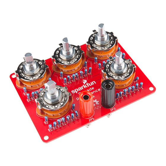
A decade box is a tool that contains resistors of many values accessed via
mechanical switches. Adjust the knobs to output any of the discrete
resistances offered by the box.
They are known as decade boxes because they have controls that
correspond to the digits in a decimal number - a control for the ones
position, a control for the tens position, a control for the hundreds position,
and so on.
Traditional decade boxes looked like something out of Dr. Frankenstein's
lab - large wooden enclosures, with engraved front panels and big Bakelite
knobs. They were available in three main types - resistance, capacitance
Advertisement

Related Manuals for sparkfun Decade Resistance Box


Summary of Contents for sparkfun Decade Resistance Box
- Page 1 Page 1 of 16 Decade Resistance Box Hookup Guide Introduction A decade box is a tool that contains resistors of many values accessed via mechanical switches. Adjust the knobs to output any of the discrete resistances offered by the box.
- Page 2 Page 2 of 16 and inductance. This kit is for a decade resistance box. It allows you to quickly and accurately dial in a specific resistance value between 0 and 999,990 Ω, in 10 Ω increments.. In this hookup guide, we’ll first assemble the decade box, then explore its application as a design aid and a test instrument.
- Page 3 Page 3 of 16 • Decoding Resistor Markings • How To Use A Multimeter Enclosure Drilling The decade resistance can be mounted in an enclosure, or used without one. If you want to put it in an enclosure, it is easiest to prepare the enclosure before the board is assembled.
-
Page 4: Electrical Assembly
Page 4 of 16 Before we start drilling, let’s take a moment to review some basic drilling safety practices, which apply whether you’re using a hand drill or a drill press. 1. Drilling aluminum produces small, sharp pieces of metal (“curliqueues”... - Page 5 Page 5 of 16 As shown above, you should have the following (clockwise from top-left) • One Decade Resistance Box PCB • Nine 10 Ω Resistors (Brown - Black - Black - Gold - Brown) • Nine 100 Ω Resistors (Brown - Black - Black - Black - Brown) •...
- Page 6 Page 6 of 16 After soldering each resistor, trim the leads close to the solder fillet. There are nine pieces of each of five different resistance values in the kit. Each value will be installed adjacent to each rotary switch. Each row is labeled with the value to be installed there.
- Page 7 Page 7 of 16 Finally, the center pin of each rotary is longer than the others. You can snip this off with cutters after soldering. Binding Posts If you’re installing the decade resistance in an enclosure, skip ahead to the next section. You’ll mount the jacks to the enclosure, rather than the PCB! Before we install them, let’s take a moment to look at how the banana jacks go together.
-
Page 8: Installation In Enclosure
Page 8 of 16 Loop the curl around the metal end of the binding post, and tighten the small nut to hold it in place. This is much easier to do if the curl points in the clockwise direction. Otherwise, tightening the nut will cause the wire to uncurl and come off the post. - Page 9 Page 9 of 16 The binding posts are also mounted somewhat differently. Secure them to the panel of the enclosure, rather than the PCB. Then install the wires on the back of the binding posts. Run the wires through the oblong holes in the PCB, and solder them in place. Carefully pull the wire slack through the holes, as you slide the PCB into the enclosure.
-
Page 10: Quick Test
Page 10 of 16 Finally, put the back on the enclosure, and attach the knobs. If you’re using the knobs recommended above, the set screw will tighten against the flat side of the shaft, 180° opposite the indicator. Quick Test With the assembly complete, you can give the decade resistance a quick test with a multimeter. -
Page 11: How It Works
Page 11 of 16 It’s worth mentioning that the meter readings in the above test will not absolutely match the settings on the decade box. For instance, the 90 Ω setting might read as 89.3 or 90.5 - very close to the ideal value, but not perfect. - Page 12 Page 12 of 16 Before we move on to some example applications of the decade resistance, let’s take a closer look at the components, because they place some limits on the decade box. With modern, low-voltage electronics, we often operate under the assumption that we aren’t using much power, or passing much current.
- Page 13 Page 13 of 16 If you need help calculating the power dissipation, check out our power tutorial. The multimeter tutorial describes how to measure the current drawn by a circuit. As a Measurement Tool Decade boxes can be very useful on an electronics test bench. One traditional application of a decade box is to measure an unknown resistance.
- Page 14 Page 14 of 16 Wheatstone Bridge In Action To test my Wheatstone bridge, I had one of my colleagues pull a random resistor from my spare parts box, and paint it over, so I couldn’t read the stripes. I built a Wheatstone bridge using a 9V battery, and 100K resistors for R and R .
- Page 15 Page 15 of 16 Sometimes, when we’re interfacing an analog signal with a microcontroller, the analog voltage doesn’t match the range of the analog-to-digital converter. For instance, the signal might swing 100 mV, but the converter is referenced to 5V - the converter would only use 2% of it’s range. To match the signal to the converter, we can build an amplifier circuit that boosts the incoming voltage.
- Page 16 • Theory behind the Wheatstone Bridge. • Moving beyond the Wheatstone bridge, the Wein Bridge uses similar nulling techniques to measure capacitors, and a Maxwell Bridge measures inductors. • An interesting anecdote from Howard Johnson regarding where precision resistors come from. https://learn.sparkfun.com/tutorials/decade-resistance-box-hookup-guide?_ga=1.111609284..8/5/2016...
Need help?
Do you have a question about the Decade Resistance Box and is the answer not in the manual?
Questions and answers