
Summary of Contents for Sensor SMT-200
- Page 1 Io SENSOR SENSOR Nederland b.v. SMT-200 v2.00 Operations and Technical Manual SMT-200 Operations and Technical Manual 2.00/R1...
- Page 2 SENSOR Page intentionally left blank SMT-200 Operations and Technical Manual 2.00/R1...
- Page 3 SENSOR Warranty CERTIFICATION SENSOR Nederland b.v. - INPUT/OUTPUT INC. certifies that this instrument meets it's published specifications at the time of shipment from the factory. WARRANTY AND ASSISTANCE This INPUT/OUTPUT INC. product is warranted against defects in materials and workmanship for a period of SIX months from the date of shipment.
- Page 4 Upon termination, you must immediately destroy the software together with all copies, adaptations and merged portions in any form. Export Requirements- You may not export or re-export the software or any copy or adaptation in violation of any applicable laws or regulations. SMT-200 Operations and Technical Manual 2.00/R1...
- Page 5 2000 compliant. Please note that during data transfer from or to the PC and during updates of the SMT-200 program, the time and date of the SMT-200 is synchronised with the time and date of the host PC.
-
Page 6: Table Of Contents
Switching off the SMT-200 Battery level Battery level Jumper setting Menu flowchart Main menu The main menu allows access to all functions of the SMT-200 2.9.1 Do a test Select this option to initiate a test sequence on a string 2.10.2 Setup menu Allows customisation of the SMT-200 operating and test parameters 2.11.2.1... - Page 7 Transfer data file Sorting the tag list 4.4.1 Download the tag list to the PC 4.4.2 Upload the tag list to the SMT-200 4.4.3 View the tag list on the SMT-200 4.4.4 View the tag list on the PC Settings 4.5.1...
- Page 8 Distortion test drive mode Continuous Impedance B.10 Low Drive Continuous Impedance B.11 Geophone String Resistance Calculation B.11.1 Series String B.11.2 Series Parallel String B.12 Damping Calculations B.13 Temperature Compensation APPENDIX C PARTS LIST SMT-200 Geophone Tester SMT-200 Operations and Technical Manual 2.00/R1...
- Page 9 SMT-200 Component Layout (SMT-200.7 01/98) SMT-200 Docking Station Schematics D.3.1 SMT-200 Docking Station / Charger D.3.2 UC3906-B1 D.3.3 UC3906-B2 SMT-200 Component Layout (SMT-200.7 CHARGER 01/98) APPENDIX E QUICK REFERENCE Quick Reference APPENDIX F ADDENDUM Addendum INDEX SMT-200 Operations and Technical Manual 2.00/R1...
- Page 10 Lbs. Pounds Suspended mass Millimeters Meters Mega byte Coil resistance Shunt resistance Total geophone resistance Volts Software version V/in/s Volts per inch per second V/m/s Volts per meter per second Volts alternating current viii SMT-200 Operations and Technical Manual 2.00/R1...
-
Page 11: Section 1 Introduction
SENSOR Section 1 Introduction Section 1 Introduction SMT-200 Operations and Technical Manual 2.00/R1... - Page 12 SENSOR Section 1 Introduction Page intentionally left blank SMT-200 Operations and Technical Manual 2.00/R1...
-
Page 13: Introduction
I/O Sensor Technical Support location for assistance. The availability of future software upgrades will be made known to SMT-200 users via the i-o web site. Your comments regarding the convenience of operation of the unit, its performance, any problems you have experienced and any features that would be useful or are in your opinion essential, would be greatly appreciated for the future development of this product. -
Page 14: Overview
Its easy to use menu system allows the SMT-200 to be quickly configured to test virtually any type of geophone string. Internal automatic calibration eliminates the need for regular maintenance. -
Page 15: Packaging Information
Two Battery packs • Docking Station • Reference geophone SM4/U-B 10Hz 375 ohm • Geophone cable Bendix to unterminated incl. temp sensor in Bendix connector • Cable SMT-200 to Docking Station, Bendix-C24 • Serial cable D9 to D9 • Serial adaptor D9 - D25 •... -
Page 16: Before Use
• If possible avoid charging battery pack at extreme ambient temperatures Remove battery pack from the SMT-200 and store safely if the SMT-200 is not to be used for an extended period of time SMT-200 Operations and Technical Manual 2.00/R1... -
Page 17: Section 2 Smt-200 Operations
SENSOR Section 2 SMT-200 Operations Section 2 SMT-200 Operations SMT-200 Operations and Technical Manual 2.00/R1... - Page 18 SENSOR Section 2 SMT-200 Operations Page intentionally left blank SMT-200 Operations and Technical Manual 2.00/R1...
-
Page 19: Layout
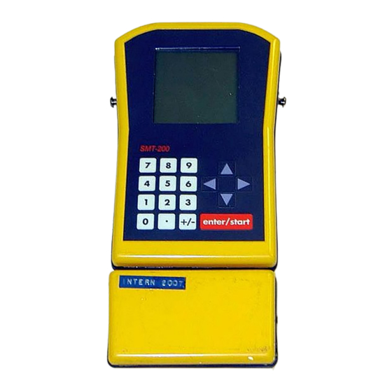
Section 2 SMT-200 Operations SMT-200 Layout The SMT-200 consists of two parts, the main case and a removable battery pack. The battery pack must be connected for mobile operation. Operation is still possible when connected to the supplied docking station, in which case the battery does not need to be connected. If the battery pack is attached to the main body the docking station will be monitoring the battery and will be automatically charging the battery as required. -
Page 20: Post Mortem On Powering Up
Abnormal shut down (e.g. battery removed) !!!!!!!!!!!!!!!! Navigating around the screens The SMT-200 operates on a simple menu system. There are two ways to access the sub-menus: Use the cursor keys to move to the required sub- CURSOR CONTROL Main menu ---------------- menu. - Page 21 1 will turn the backlight on or off. The backlight can now be turned on or off by repeatedly hitting the 1 key. Hit 0 then 0 to return to the Main menu. SMT-200 Operations and Technical Manual 2.00/R1...
- Page 22 0 Back to Setup ---------------- ---------------- Enter test mode Submenu for Select display String Config. back-light The shorthand notation for these actions that is used throughout the manual is [2-6-1] which signifies the keystrokes needed SMT-200 Operations and Technical Manual 2.00/R1...
-
Page 23: Switching Off The Smt-200
10.7 volts. NOTE: In the rare case that the SMT-200 locks up and cannot be shut down at all then the only way to reset the tester is to remove the battery pack. USE ONLY AS A LAST RESORT. -
Page 24: Battery Level
Battery charge condition is monitored and displayed as a bar graph indicator, which is visible in the Main menu, Do a test and Diagnostics Battery test screens. It provides the user with a guide of the remaining operational time of the SMT-200 with the attached battery pack. Bar Graph Indicator of battery status:... -
Page 25: Battery Level Jumper Setting
Section 2 SMT-200 Operations Battery level Jumper setting Function of the battery level monitoring requires that jumper JP5 located on the SMT-200 main PCB be set to the BatTst position. When upgrading software on older SMT-200’s it’s possible that this jumper may need to be repositioned. -
Page 26: Menu Flowchart
0.04 % 2205 ohm structure shown on structure shown on GEOPHONE TESTER Test OK Page 17 Page 18 Version 2.00 SMT200-2001 0 Back to Main Compiled at - Repeat Test Start next Test 04/02/00 02:00 SMT-200 Operations and Technical Manual 2.00/R1... - Page 27 Up, Down keys 0 Back to Setup ---------------- ---------------- ---------------- ---------------- ---------------- Low drive level Select display Enable / Disable Calibrate Iopa cont. impedance back-light Power save mode Enter - to Setup for Leakage test SMT-200 Operations and Technical Manual 2.00/R1...
- Page 28 Reading Config Saving Config In the following description the bold item represents the section and the remaining digits represent the keystrokes required to access the selection. Section 2.5.2.6.1 Backlight on/off Keystrokes (In this case SMT-200 Operations and Technical Manual 2.00/R1...
-
Page 29: Do A Test Select This Option To Initiate A Test Sequence On A String
SENSOR Section 2 SMT-200 Operations Main menu The main menu allows access to all functions of the SMT-200 Do a test… Acquire test record. Setup menu… Enables you to set the parameters of the string Main menu --------------- under test, tests to be performed and miscellaneous 1>Do a test... -
Page 30: Setup Menu Allows Customisation Of The Smt-200 Operating And Test Parameters
SENSOR Section 2 SMT-200 Operations 2.10.2 Setup menu Allows customisation of the SMT-200 operating and test parameters 2>Setup menu... Setup menu String menu Setup string configuration & shunt resistor options. ---------------- Geophone menu Select or edit geophone element used in strings. -
Page 31: Limits Menu Sets Maximum Allowable Limits For Various Tests
6 geophone elements wired as group A and group B. Both group A and B consist of 3 elements in series. There are 2 parallel groups A and B. This information allows the SMT-200 to determine the strings geometry. The string shown here incorporates damping resistors so the shunt option [2-1-7] should be set to YES and the value [2-1-8] set to 1000. -
Page 32: Select Menu Selects The Type Of Geophone Element Used
, a new description will be generated with the filename *newspec# where # is the allocated ENTER/START sequential file number. This will then be the selected geophone. 2.16.2.2.4 Delete Deletes an existing element description , the currently selected element description will be deleted. ENTER/START SMT-200 Operations and Technical Manual 2.00/R1... -
Page 33: Operating Menu General Options For String Testing
In the first case there is no temperature adjustment performed on the data but the original specs. Alternatively the uncompensated specs can be used in which case the data will be temperature compensated. See section 2.5.3. SMT-200 Operations and Technical Manual 2.00/R1... -
Page 34: Tests Sequence Selects The Tests To Be Performed On The String
2 LCD Contrast + 3 LCD Contrast - LCD Contrast- Decreases contrast of LCD display. 4 Beeps ON Beeps Enables or disables SMT-200 warning tones. 5 Key Beeps ON 6 Metric units Key Beeps Enables or disables keyboard feedback tones. Metric Units Toggles between metric and imperial units. -
Page 35: Power Menu Selects The Various Power Saving Options
5 Log-Off 3 s last key press in minutes. Shut-Down Sets the time the SMT-200 remains on for before beginning an auto shutdown sequence in minutes. 0 Back to Setup This time is reset with each key press. No data is ---------------- lost if the unit does shut down automatically. -
Page 36: Diagnostics Runs The Diagnostics And Calibration Routines
Section 2 SMT-200 Operations 2.22.2.9 Diagnostics Runs the diagnostics and calibration routines NOTE: Use the Diagnostics test plug (part number SMT-200 C 0515) where indicated. When exiting Diagnostics Test routine all settings are restored to original values. 2>Setup menu... 9>Diagnostics... - Page 37 Exit test by pressing any 4 Battery key. 5 Relay ExTemp SMT-200 external temperature probe is continually 6 Sine wave... measured and displayed. If no probe is connected message n/a is displayed. Exit test by pressing any 0 Back to diagn.
-
Page 38: Temp. Menu Read Or Set The External Temperature And Temperature Options
Temp. menu Read or set the external temperature and temperature options It is important to compensate the SMT-200 results to allow for temperature variations. The materials used within the string itself have a temperature coefficient, which means the geophone properties will change with temperature. - Page 39 Assuming any deviation from the nominal value at 20°C is due to temperature variation the actual temperature can be calculated. There is a Smartec temperature sensor built into the Bendix connector of the SMT-200. It is important to make sure that the temperature of this connector is the same as the temperature of the geophones under test.
-
Page 40: File Menu Internal File Handling And Data / Code Transfer Options
Shows the result of the last test run 4>File menu... 1>Redisplay last lay Last ---------------- Temp 21.6 If a test has not been run since the SMT-200 was switched on there will be Leak 9.2 Mohm no meaningful data shown. 394 ohm Freq 10.35 Hz Damp 0.242... -
Page 41: Storage Status Indicates The Internal Memory Storage
Storage status ---------------- Stored Records: The SMT-200 can store around 16000 records. The Storage status will let you see exactly how many records are held in memory and the estimated Estimated space: number of subsequent records that can be stored. -
Page 42: List Data File List Contents Of Data File
0 to cancel command. Once erased 6 Read Config ENTER/START 7 Save Config the data file cannot be recovered. 0 Back to Main ---------------- Erase ALL data ( Be careful ! ) SMT-200 Operations and Technical Manual 2.00/R1... -
Page 43: Read Config Loads The Stored Configuration File
1 Redisplay last 2 Storage status 3 Dump data file The configuration file holds all the parameters that setup the SMT-200. The 4 List data file file is automatically loaded and saved on power up and shutdown. Read 5 Erase ALL data 6>Read Config... -
Page 44: About Provides General Information About The Smt-200
SENSOR Section 2 SMT-200 Operations 2.32.6 About Provides general information about the SMT-200 6>About... SENSOR “Version” shows the software revision of the code. SMT-200 “SN” gives the serial number of the unit. “Compiled at” gives the date and time of when the software was compiled. - Page 45 SENSOR 3 Docking Station & PC Software Operations Section 3 Docking Station & PC Software Operations SMT-200 Operations and Technical Manual 2.00/R1...
- Page 46 SENSOR Section 3 Docking Station & PC Software Operations Page intentionally left blank SMT-200 Operations and Technical Manual 2.00/R1...
- Page 47 3 Docking Station & PC Software Operations Docking Station overview The Docking station has two main functions: • Battery charging. • Interfaces SMT-200 to PC for data exchange and software updates. Charging connector for spare battery Geophone Terminals Leakage Probe...
- Page 48 SMT-200 to the Docking Station for data downloading or recharging it is advisable to first ensure the power is off on the docking station and SMT-200. Connect the PC to the docking station with the 9 pin D9 to D9 connector supplied. Next connect the SMT-200 to the docking station with the Bendix to Centronics 24 way cable supplied.
- Page 49 Docking Station PC software introduction The Docking Station software allows you to: • Download the data file from the SMT-200. • Synchronise the SMT-200 date and time with PC’s date and time. • Upload SMT-200 configuration and specifications files. • Upload SMT-200 software upgrades.
- Page 50 DOS un-install The program files need to be removed manually using the DOS comands Del and RMdir. Please consult your DOS manual for further details. Note SMT-200 data is stored in a separate directory. SMT-200 Operations and Technical Manual 2.00/R1...
- Page 51 The Function keys and the ALT give you a keyboard shortcut to menu items. Select functions by using F10 together with the menu item coloured letter. Menu items that have three dots (...) following the description have an associated submenu. SMT-200 Operations and Technical Manual 2.00/R1...
- Page 52 Tag file upload please see Appendix D for detail on this feature System Update is used to upload new SMT-200 software. The version of code held on disk will be copied to the SMT-200 if newer than the software already loaded in the SMT-200.
- Page 53 NOTE: If the configuration or the geophone specification file (SMT200.CFG & SPC.TXT) on the PC are a later date than the same file in the SMT-200 they will be automatically updated from PC during the File Transfer sequence. This may overwrite and thus alter test specs. in the SMT-200. It is generally recommended to change test specs.
- Page 54 • The SMT-200 to Docking Station cable is not connected properly. • Docking Station's power is off: the SMT-200 will be switched on however, but the communications circuit needs power. • PC is not ready, i.e. other processor tasks are taking too long, causing time-out errors.
- Page 55 Technical Note: When downloading a file from PC to the SMT-200, the old version is put into the free memory first. If transfer fails then it is restored. When transfer fails within a minute the SMT-200 will reboot. This is the reason why it could be fatal to interrupt a failing transfer by just switching off the power and/or disconnecting the battery.
- Page 56 SENSOR Section 3 Docking Station & PC Software Operations Page intentionally left blank SMT-200 Operations and Technical Manual 2.00/R1...
- Page 57 SENSOR Section 4 RF/ID Tag Reader Section 4 RFID Tag Reader SMT-200 Operations and Technical Manual 2.00/R1...
- Page 58 SENSOR Section 4 RF/ID Tag Reader Page intentionally left blank SMT-200 Operations and Technical Manual 2.00/R1...
- Page 59 RFID Tag reader introduction When testing geophones strings using the SMT-200 a test identification or the string number must first be allocated to each string test. This number can normally to be found as an ID label attached to the string.
- Page 60 SENSOR Section 4 RF/ID Tag Reader Working with the RFID Tag reader To test strings using an SMT-200 with tag reader takes three steps: • Read tags to create a tag list containing the tag ID and associated string number.
- Page 61 SENSOR Section 4 RF/ID Tag Reader Using the SMT-200 keypad, enter the required number. This number will be Read tags displayed under the text String No. If you make an error you can use the left ---------------- arrow to erase the last digit. If the default number is the string number you...
- Page 62 Upon completion of testing, test data can be downloaded to the PC via the Docking Station program. Connect the SMT-200 to the PC and start the Docking Station program. Select the menu option SMT-200, File Transfer. The SMT-200 now downloads the data file to the PC.
- Page 63 Sorting the tag list is very easy. Each file transfer the unsorted part of the tag list is downloaded to the PC and stored as a text file. When you upload this file from the PC to the SMT-200 it is automatically sorted.
- Page 64 A ‘busy’ message is displayed. You can quit by pressing Esc. After the conversion is finished, a report is displayed where error messages are displayed. Normally there will be no messages. The tags displayed in the conversion report are removed from the converted list. SMT-200 Operations and Technical Manual 2.00/R1...
- Page 65 When you type a number, the SMT-200 searches in the sorted list for the first tag that is equal or greater. You can remove the last digit with the left arrow. Leave this option by pressing the right arrow.
- Page 66 Select the required file for viewing by clicking on it with the mouse. Click on the Open button or press Enter. The tag list will be displayed. 1000001779850 1000001779999 1000001802291 1000001802292 The left hand column contains the tag ID and the right hand string numbers entered by the user. SMT-200 Operations and Technical Manual 2.00/R1...
- Page 67 Section 4 RF/ID Tag Reader Settings 4.5.1 COM settings When using the Tag reader the SMT-200 baud rate can be set in the menu SMT-200, COM settings. The tag reader baud rate must be set to 9600 baud. 4.5.2 Autonumber When the Autonumber option is ON and you are testing a ‘new’...
- Page 68 Internal storage With the SMT-200 and a RFID tag reader you can read unique, 40 bits, tags. The user can link a variable string number to it (1 <= String number < 100.000). The maximum amount of tags is 120.000.
- Page 69 SENSOR Section 5 Geophone Testing Section 5 Geophone Testing SMT-200 Operations and Technical Manual 2.00/R1...
- Page 70 SENSOR Section 5 Geophone Testing Page intentionally left blank SMT-200 Operations and Technical Manual 2.00/R1...
- Page 71 (Section A.6) for more details. First thing to do is check that the geophone type is in the SMT-200 library. If the geophone type is not listed in the SMT-200 library copy it from another geophone description and edit the required parameters accordingly.
- Page 72 11. Select 3 to go to the Operating menu. Operating menu ---------------- 1>Autonumber ON For general use the autonumber is normally on. Sensor recommends that 2 Save Rej's YES distortion is tested at constant excursion and temperature correction is on 3 Full Test 4 Cont on reject data.
- Page 73 However the new information has not been saved to the solid state memory at this stage. This will be done when the SMT-200 powers off or can be done manually by the Save Config option in the File menu.
- Page 74 Downloading data to a PC By this stage, if all has gone well there will be a sequence of records stored in the SMT-200 memory. These are quite safe and can only be erased by going into the file menu to erasing the data. More often that not the data will need to be downloaded to a PC and from there possibly to a spreadsheet.
- Page 75 Sensitivity High Sensitivity Low Distortion High Dist. far High Noise High Freq. Tilt High Freq. Tilt Low Dist. Tilt High Short Circuit Open Circuit Polarity Reversed Test OK Test OK SIMULATION Leakage Leakage Overflow SMT-200 Operations and Technical Manual 2.00/R1...
- Page 76 (The actual value is not important it can take any range Temp 24.2 of values, there is no right or wrong value in this case). 2112 ohm <2069> <2153>> +/- New Ref Now Testing Cont Imp..SMT-200 Operations and Technical Manual 2.00/R1...
- Page 77 TIP: When running the continuous impedance for fault finding use the +/- key instead of the . Using the key will cause the result of the test to be logged to the internal ENTER/START ENTER/START memory. This technique can also be applied to regular tests as well. SMT-200 Operations and Technical Manual 2.00/R1...
- Page 78 1401 Mohm on resistance but sensitivity is ok then it is possible the temperature of the *398 ohm string is incorrectly set. Check the Smartec sensor is enabled and the Freq 9.91 Hz SMT-200 Bendix connector (containing the sensor) is at a similar Damp 0.259...
- Page 79 An example of a simple isolation table is shown below. Cases with spikes require holes Heavy piece of wood to be drilled in the top (Railway Sleeper size) Car Inner-Tube SMT-200 Operations and Technical Manual 2.00/R1...
- Page 80 SENSOR Section 5 Geophone Testing Page intentionally left blank SMT-200 Operations and Technical Manual 2.00/R1...
- Page 81 SENSOR Section 6 SMT-200 Technical Section 6 SMT-200 Technical SMT-200 Operations and Technical Manual 2.00/R1...
- Page 82 SENSOR Section 6 SMT-200 Technical Page intentionally left blank SMT-200 Operations and Technical Manual 2.00/R1...
- Page 83 SSD via a PC connected to the Docking Station. The PC/104 board is highly integrated and repairs to the card are not advised. If the card is in doubt the entire SMT-200 should be returned to the nearest I/O SENSOR service location for repair.
- Page 84 DRQ3 SA14 -DACK1 SA13 DRQ1 SA12 -REFRESH W1 - Byte-wide (S0) configuration SA11 W2 - Byte-wide (S0)configuration SA10 IRQ7 W4 - 12V flash programming power IRQ6 IRQ5 IRQ4 IRQ3 -DACK2 BALE PC-104 Bus Connector SMT-200 Operations and Technical Manual 2.00/R1...
- Page 85 Section 6 SMT-200 Technical SMT-200 Main Board block diagram This section contains a functional description of the SMT-200 main board. The board contains all the required circuitry to generate the test signals for the geophones and digitise the signals via the A-D converter.
- Page 86 The address decoder shown on sheet 7. of the SMT-200 Schematic. The SMT-200 hardware is mapped into the PC I/O locations by U1, U3 and U4. The output of U4 (pin 8) is low when there is an I/O read or write to a valid (1B0h to 1BFh) location. This is further decoded by U1 to generate the enable signals for the various devices.
- Page 87 ENTER/START Digital to Analogue Converter The digital to analogue converter circuit is shown on sheet 7 of the SMT-200 Schematic. The digital to analogue converter (DAC) is formed around a lookup table stored in the EPROM, U12. This contains the digital values for a low distortion sine wave. The clock for each sample starts at the PC speaker.
- Page 88 6.12 Analogue to Digital Converter The A to D circuit is shown on sheet 2. of the SMT-200 Schematic. The A to D is based on U6. This is a CMOS based 16-Bit sampling A to D converter using a successive approximation technique.
- Page 89 Note: The power connector (J5) on the PC/104 board is not used. Power for the this board is derived from the 5 V regulator on the main board and fed to the PC/104 via JP3. SMT-200 Operations and Technical Manual 2.00/R1...
- Page 90 SENSOR Section 6 SMT-200 Technical Page intentionally left blank SMT-200 Operations and Technical Manual 2.00/R1...
- Page 91 Io SENSOR Section 7 Docking Station Technical Section 7 Docking Station Technical SMT-200 Operations and Technical Manual 2.00/R1...
- Page 92 SENSOR Section 7 Docking Station Technical Page intentionally left blank SMT-200 Operations and Technical Manual 2.00/R1...
- Page 93 • Battery Charging 110 VAC Transformer 220 VAC Battery +13.8 V +25 V DC & Charger Bridge Rectifier EXTERNAL BATTERY CONNECTOR Battery Charger Regulator SMT-200 CONNECTOR TEMPERATURE PROBE CONNECTOR GEOPHONE CONNECTOR LEAKAGE CONNECTOR RS232 RS232 CONNECTOR SMT-200 Operations and Technical Manual 2.00/R1...
- Page 94 2) Q8 will not conduct regardless if Q11 is on or off preventing the green LED from illuminating. The Charger #1 (SMT-200) is very similar with the addition of a relay. Relay K1 will energise when the SMT-200 is switched on, adding R16 into the circuit. The effect of this to the change the point the...
- Page 95 Io SENSOR Section 7 Docking Station Technical circuit switches from State 3 to State 4 from 10% to 50%. This allows for the extra current drawn by the SMT-200 when it’s on. SMT-200 Operations and Technical Manual 2.00/R1...
- Page 96 SENSOR Section 7 Docking Station Technical Page intentionally left blank SMT-200 Operations and Technical Manual 2.00/R1...
- Page 97 SENSOR Appendix A Connector Pinouts Appendix A Connector Pin outs SMT-200 Operations and Technical Manual 2.00/R1...
- Page 98 SENSOR Appendix A Connector Pinouts Page intentionally left blank SMT-200 Operations and Technical Manual 2.00/R1...
- Page 99 NAME Charger V+ Charger V- Shield Geophone - Geophone Leak Smartec EXT Smartec GND Shield (nc) Charger V+ Charger V- (nc) Geophone + Geophone Shield Smartec V+ ON/OFF (view from rear of Docking Station) SMT-200 Operations and Technical Manual 2.00/R1...
- Page 100 Appendix A Connector Pinouts Docking Station External Smartec Connector NAME (nc) Smartec EXT Smartec V+ Smartec GND (nc) (nc) (view from rear of Docking Station) Docking Station PC Connector NAME (view from rear of Docking Station) SMT-200 Operations and Technical Manual 2.00/R1...
- Page 101 Smartec should be taken out of the Bendix and mounted on a flying lead. The sensor can then be left close to the string under test to give an accurate indication of string temperature.
- Page 102 Smartec GND White/Black ON / OFF Red/Blue 8 & 3 Shield (Case) Shield Grey/Green Grey/Pink Brown/Blue Brown/Yellow Brown/Red Brown/Pink Brown/Green Brown/Black Brown/Grey (unused) Brown (unused) White (unused) White/Grey (unused) White/Pink (unused) White/Green (unused) White/Blue SMT-200 Operations and Technical Manual 2.00/R1...
- Page 103 SENSOR Appendix B Test Overview Appendix B Test Overview SMT-200 Operations and Technical Manual 2.00/R1...
- Page 104 SENSOR Appendix B Test Overview Page intentionally left blank SMT-200 Operations and Technical Manual 2.00/R1...
- Page 105 The fundamental principle the SMT-200 uses for its tests is the idea that conductors breaking magnetic flux lines producing a current can be applied in reverse. The SMT-200 can apply current to a phone under test which will physically move the coil. This movement will indirectly produce a voltage we can measure.
- Page 106 TEST PRINCIPLE……… The SMT-200 monitors the output of the geophone for 800 samples over 96 ms, the average level of noise is then computed. The lower the noise valve the better. In practice (depending on the geophone string confoguration) a result of less than 30mV ambient noise ng picked up will not effect the results.
- Page 107 The normal way of doing this is a process know as damping. SMT-200 Operations and Technical Manual 2.00/R1...
- Page 108 Shunt resistors have an effect on the sensitivity of the geophone and so does the recording systems input stages. The seismic detector response curves shown in the Sensor geophone specification sheets show the open circuit (OC) damping sensitivity curve at the top and the damping curve with various values of shunt resistors underneath.
- Page 109 In the case of the SMT-200 the test frequency is determined by the user but for each period during the recording interval, 32 samples are taken and averaged. The result is then converted to the frequency domain so a 32 point FFT can be applied to work out the fundamental, second and third harmonics.
- Page 110 The low drive continuous impedance test applies a user defined low drive (default 10% of the nominal drive level) to the geophone string under test so that sticking or dragging coils can be found whereby if a higher drive level was used the coil would be freed. SMT-200 Operations and Technical Manual 2.00/R1...
- Page 111 6 series geophones and 3 parallel branches. The formulas used in B.8.1 can be used for this. In that particular instance we would end up with a branch resistance of 1638 Ω. Divide this number by the number of branches. 1638 Ω SMT-200 Operations and Technical Manual 2.00/R1...
- Page 112 = Resistance at 20 ºC − − Tspec = Damping at 20 ºC = Damping at temperature t = Sensitivity at temperature t = Sensitivity at 20 ºC = Temperature Tspec = Geophone temperature spec. SMT-200 Operations and Technical Manual 2.00/R1...
- Page 113 SENSOR Appendix C Parts List Appendix C Parts List SMT-200 Operations and Technical Manual 2.00/R1...
- Page 114 SENSOR Appendix C Parts List Page intentionally left blank SMT-200 Operations and Technical Manual 2.00/R1...
- Page 115 T 0030 SMT-200 T 0031 649k SMT-200 T 0032 66k5 SMT-200 T 0033 SMT-200 T 0034 80k6 SMT-200 T 0035 R10,R11 Trim Pot 100k SMT-200 T 0036 EMC1,EMC2,EMC3,EMC4 GND Resistor Option SMT-200 T 0037 SMT-200 Operations and Technical Manual 2.00/R1...
- Page 116 T 0071 CD74HCT00 SMT-200 T 0072 CD74HCT139 SMT-200 T 0073 CD74HCT245 SMT-200 T 0074 U4,U14 CD74HCT30 SMT-200 T 0075 DAC707 SMT-200 T 0076 DG408DJ / ADG408BN SMT-200 T 0077 DG409DJ / ADG409BN SMT-200 T 0078 SMT-200 Operations and Technical Manual 2.00/R1...
- Page 117 A8200111 PCB assembly I M3 x 8 Phillips cross recessed cheese head screw SMT-200 T 0117 A8200111 PCB assembly I M4 Lock washer SMT-200 T 0118 A8200114 PCB support assemblies M4 Lock washer SMT-200 T 0119 SMT-200 Operations and Technical Manual 2.00/R1...
- Page 118 T 0154 A8200147 Case bottom assembly IV SMT-200 Male slide plate SMT-200 T 0155 A8200147 Case bottom assembly IV SMT-200 Male slide plate, Contact block SMT-200 T 0156 A8200145 Case bottom assembly III SMT-200 Male slide plate, Contact pin SMT-200...
-
Page 119: Battery Pack
A8200220 SMT-200 Battery Pack SMT-200 Battery Pack SMT-200 B 0200 Battery 12V 1.2Ah SMT-200 B 0201 A8200211 Bottom assembly SMT-200 Female slide plate (battery pack) SMT-200 B 0202 A8200211 Bottom assembly SMT-200 Female slide plate, insulation plate SMT-200 B 0203 A8200211 Bottom assembly... -
Page 120: Docking Station
DS 0332 A8200305 LED & geo cable D5, D8 DUAL LED CC SMT-200 DS 0333 A8200305 LED & geo cable D2 LED Green SMT-200 DS 0334 LM7805 SMT-200 DS 0335 U6,U7 UC3906 SMT-200 DS 0336 SMT-200 Operations and Technical Manual 2.00/R1... - Page 121 DS 0361 A8200321 Case assembly I M3 Washer SMT-200 DS 0362 A8200321 Case assembly I M3 x 12 Phillips cross recessed count. sunk screw SMT-200 DS 0363 A8200312 Chassis assembly II M3 x 12 Slotted pan head screw SMT-200 DS 0364...
-
Page 122: Accessories And Cables
SMT-200 DS 0387 A8200321 Case assembly I SMT-200 Male slide plate SMT-200 DS 0388 A8200321 Case assembly I SMT-200 Male slide plate contact block SMT-200 DS 0389 A8200321 Case assembly I SMT-200 Male slide plate contact pin SMT-200 DS 0390... -
Page 123: Appendix D Schematics & Layouts
SENSOR Appendix D Schematics & Layouts Appendix D Schematics & Layouts SMT-200 Operations and Technical Manual 2.00/R1... - Page 124 SENSOR Appendix D Schematics & Layouts Page intentionally left blank SMT-200 Operations and Technical Manual 2.00/R1...
-
Page 125: Schematics
SENSOR Appendix D Schematics & Layouts SMT-200 Schematics D.1.1 SMT-200 Geophone Tester SMT-200 Operations and Technical Manual 2.00/R1... -
Page 126: Adc
SENSOR Appendix D Schematics & Layouts D.1.2 SMT-200 ADC SMT-200 Operations and Technical Manual 2.00/R1... -
Page 127: Filter
SENSOR Appendix D Schematics & Layouts D.1.3 SMT-200 Filter SMT-200 Operations and Technical Manual 2.00/R1... -
Page 128: Keyboard
SENSOR Appendix D Schematics & Layouts D.1.4 SMT-200 Keyboard SMT-200 Operations and Technical Manual 2.00/R1... -
Page 129: Dac
SENSOR Appendix D Schematics & Layouts D.1.5 SMT-200 DAC SMT-200 Operations and Technical Manual 2.00/R1... -
Page 130: Geophone Circuit
SENSOR Appendix D Schematics & Layouts D.1.6 SMT-200 Geophone Circuit SMT-200 Operations and Technical Manual 2.00/R1... -
Page 131: Power
SENSOR Appendix D Schematics & Layouts D.1.7 SMT-200 Power SMT-200 Operations and Technical Manual 2.00/R1... -
Page 132: Display
SENSOR Appendix D Schematics & Layouts D.1.8 SMT-200 Display SMT-200 Operations and Technical Manual 2.00/R1... -
Page 133: Component Layout (Smt-200.7 01/98)
SENSOR Appendix D Schematics & Layouts SMT-200 Component Layout (SMT-200.7 01/98) SMT-200 Operations and Technical Manual 2.00/R1... -
Page 134: Docking Station Schematics
SENSOR Appendix D Schematics & Layouts SMT-200 Docking Station Schematics D.3.1 SMT-200 Docking Station / Charger SMT-200 Operations and Technical Manual 2.00/R1... -
Page 135: Uc3906-B1
SENSOR Appendix D Schematics & Layouts D.3.2 UC3906-B1 SMT-200 Operations and Technical Manual 2.00/R1... -
Page 136: Uc3906-B2
SENSOR Appendix D Schematics & Layouts D.3.3 UC3906-B2 SMT-200 Operations and Technical Manual 2.00/R1... -
Page 137: Component Layout (Smt-200.7 Charger 01/98)
SENSOR Appendix D Schematics & Layouts SMT-200 Component Layout (SMT-200.7 CHARGER 01/98) SMT-200 Operations and Technical Manual 2.00/R1... - Page 138 SENSOR Appendix D Schematics & Layouts Page intentionally left blank SMT-200 Operations and Technical Manual 2.00/R1...
-
Page 139: Appendix E Quick Reference
SENSOR Appendix E Quick Reference Appendix E Quick Reference SMT-200 Operations and Technical Manual 2.00/R1... - Page 140 SENSOR Appendix E Quick Reference Page intentionally left blank SMT-200 Operations and Technical Manual 2.00/R1...
-
Page 141: Quick Reference
2 6 1 Display - Backlight on time (power saving) Enter Value B-Light 2 7 2 Display - Contrast decrease LCD Contrast 2 6 3 2 6 2 Display - Contrast increase LCD Contrast SMT-200 Operations and Technical Manual 2.00/R1... - Page 142 String - Test number Enter Value 2 1 1 String configuration menu String menu Tag - Display tag list & test/string number Tag list Tag - Read tag & allocate/display test/string number Read tags SMT-200 Operations and Technical Manual 2.00/R1...
- Page 143 Test number Enter Value 2 1 1 Test with a Constant Excursion Toggle @ Constant Exc. 2 3 5 Test with a Constant Velocity Toggle @ Constant Vel. 2 3 5 Tests Sequence Tests Sequence SMT-200 Operations and Technical Manual 2.00/R1...
- Page 144 SENSOR Appendix E Quick Reference Page intentionally left blank SMT-200 Operations and Technical Manual 2.00/R1...
-
Page 145: Appendix F Addendum
SENSOR Appendix F Addendum Appendix F Addendum SMT-200 Operations and Technical Manual 2.00/R1... - Page 146 SENSOR Appendix F Addendum Page intentionally left blank SMT-200 Operations and Technical Manual 2.00/R1...
-
Page 147: Addendum
SENSOR Appendix F Addendum Addendum SMT-200 Operations and Technical Manual 2.00/R1... - Page 148 SENSOR Appendix F Addendum Page intentionally left blank SMT-200 Operations and Technical Manual 2.00/R1...
-
Page 149: Index
Geophone Specifications File ....... 45 Damping ............4, 19 Data Download ..........42 Data Exchange ..........43 Data file name ..........42 Hardware ............27 Data transfer sequence .........43 Harmonic Distortion ........4 Date & Time..........20, 25 DC Gain ............28 SMT-200 Operations and Technical Manual 2.00/R1... - Page 150 Tag list downloading to PC ......53 Polarity.............19, 24 Tag list sorting..........53 Polarity Sensitivity .........21 Tag menu..........19, 50 Post Mortem ..........10, 26 Tag menu visible........... 57 Power menu ..........20, 25 Tag Number ..........52 SMT-200 Operations and Technical Manual 2.00/R1...
- Page 151 Test codes .............65 View File ............52 Test number ..........20 View tag list on PC........55 Test Sequence ..........20 View tag list on SMT-200 ......55 Test Storage ............5 Voltage selection..........6 Testing strings .........51, 63 Tests ..............28 Tests Sequence..........24 Windows installation ........
- Page 152 SENSOR Notes Notes: SMT-200 Operations and Technical Manual 2.00/R1...
Need help?
Do you have a question about the SMT-200 and is the answer not in the manual?
Questions and answers