
Subscribe to Our Youtube Channel
Related Manuals for Analog Devices ADZS-21569-EZKIT


Summary of Contents for Analog Devices ADZS-21569-EZKIT
- Page 1 ADZS-21569-EZKIT Manual Revision 1.0, August 2019 Part Number 82-000965-01 Analog Devices, Inc. One Technology Way Norwood, MA 02062-9106...
- Page 2 Analog Devices, Inc. reserves the right to change this product without prior notice. Information furnished by Ana- log Devices is believed to be accurate and reliable. However, no responsibility is assumed by Analog Devices for its use; nor for any infringement of patents or other rights of third parties which may result from its use. No license is granted by implication or otherwise under the patent rights of Analog Devices, Inc.
- Page 3 The ADZS-21569-EZKIT evaluation board contains ESD (electrostatic discharge) sensitive devices. Electrostatic charges readily accumulate on the human body and equipment and can discharge without detection. Permanent damage may occur on devices subjected to high-energy discharges. Proper ESD precautions are recommended to avoid performance degradation or loss of functionality.
- Page 4 Manual Contents ............................1–1 Technical Support ............................1–1 Supported Integrated Circuit ......................... 1–1 Supported Tools............................. 1–2 Product Information ............................1–2 Analog Devices Website..........................1–2 EngineerZone ............................. 1–2 Using the Board Product Overview ............................2–1 Package Contents............................2–3 Default Configuration ........................... 2–3 Debug Interface .............................
- Page 5 GPIO ( LED7, LED10, LED9 )......................3–14 Reset ( LED11 ) ............................3–15 Connectors ..............................3–15 S/PDIF Optical Tx ( J1 )......................... 3–15 Clock ( J2 ).............................. 3–16 Audio Input/Output ( J3 )........................3–16 Link Port/JTAG ( J8 and J9 ) ......................3–16 ADZS-21569-EZKIT Manual...
- Page 6 B ( P10 and P11 ) ........................... 3–18 Engine RPM ( P12 ) ..........................3–18 Microphone ( P13-P16 )........................3–18 Power Plug ( P10 )........................... 3–18 Power Terminal Block ( P22 ) ........................3–19 Expansion Interface 3 ( P9 and P7 ) ....................3–19 ADZS-21569-EZKIT Manual...
- Page 7 Preface 1 Preface Thank you for purchasing the Analog Devices, Inc. ADZS-21569-EZKIT evaluation system. Purpose of This Manual This manual provides instructions for installing the product hardware (board). This manual describes operation and configuration of the board components and provides guidelines for running code on the board.
- Page 8 If you are a registered user, just log on. Your user name is your e-mail address. EngineerZone EngineerZone is a technical support forum from Analog Devices, Inc. It allows you direct access to ADI technical support engineers. You can search FAQs and technical information to get quick answers to your embedded process- ing and DSP design questions.
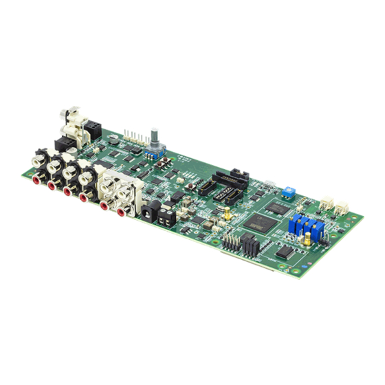
- Page 9 This chapter provides information on the major components and peripherals on the board, along with instructions for installing and setting up the emulation software. Product Overview The board features: • Analog Devices ADSP-21569 processor • 400 ball BGA • 25 MHz oscillator • DDR3 Memory •...
- Page 10 Product Overview • Analog Devices ADAU1962A - 12 Channel, High Performance, 192kHz, 24-Bit DAC • Analog Devices ADAU1977 - Quad ADC with Diagnostics • Analog Devices ADAU1979 - Quad Analog-to-Digital Converter • 12 RCA connectors. 12 outputs or 8 outputs/4 inputs •...
- Page 11 • Universal 12V DC power supply • USB 2.0 type A to micro-B cable • ICE-1000 emulator Contact the vendor where you purchased your ADZS-21569-EZKIT evaluation board or contact Analog Devices, Inc. if any item is missing. Default Configuration The ADZS-21569-EZKIT board is designed to run as a standalone unit.
- Page 12 Refer to the readme file provided with each example for more information. Reference Design Information A reference design info package is available for download on the Analog Devices Web site. The package provides information on the schematic design, layout, fabrication, and assembly of the board.
- Page 13 The ADAU1962A is a high performance, single-chip digital-to-analog converter (DAC) that provides 12 DACs with differential or single-ended output using the Analog Devices, Inc., patented multibit sigma-delta (Σ-Δ) archi- tecture. A serial peripheral interface (SPI)/I2C port is included, allowing a micro-controller to adjust volume and many other parameters.
- Page 14 ADAU1977 - Quad ADC with Diagnostics bit clock. The DACs are designed using the latest Analog Devices continuous time architectures to further minimize EMI. ADAU1977 - Quad ADC with Diagnostics The ADAU1977 incorporates four high performance analog-todigital converters (ADCs) with direct-coupled inputs capable of 10 V rms.
- Page 15 IS25LP512M - 512M-bit Serial Flash Memory with Dual and Quad SPI The IS25LP512M and IS25WP512M Serial Flash memory offers a versatile storage solution with high flexibility and performance in a simplified pin count package. ISSI’s “Industry Standard Serial Interface” Flash is for systems ADZS-21569-EZKIT Manual 2–7...
- Page 16 I/O mode. The three bus signals are a clock input (SCLK), a serial data input (SI), and a serial data output (SO). Serial access to the device is enabled by CS# input. The MX66LM1G45G MXSMIO® (Serial Multi I/O) provides sequential read operation on whole chip. 2–8 ADZS-21569-EZKIT Manual...
- Page 17 Hardware Reference 3 Hardware Reference This chapter describes the hardware design of the ADZS-21569-EZKIT . System Architecture The board's configuration is shown in the Block Diagram figure. ADZS-21569-EZKIT Manual 3–1...
- Page 18 C software-control- led switches. The remaining mechanical switches are provided for the boot mode and pushbuttons. Reference any SoftConfig*.c file found in the installation directory for an example of how to set up the SoftConfig feature of 3–2 ADZS-21569-EZKIT Manual...
- Page 19 EXAMPLE_SIGNAL_B, the Microchip IO expander is used to change ENABLE_A to a logic 1 through software that interfaces with the Microchip. The same procedure for ENABLE_B disconnects EXAMPLE_SIGNAL_C from EXAMPLE_SIGNAL_D. Figure 3-2: Example of Individual FET Switches ADZS-21569-EZKIT Manual 3–3...
- Page 20 In this example, the Microchip IO expander is not shown but controls the signal CONTROL_LETTER_NUMBER and allows the user to change the selection through software. 3–4 ADZS-21569-EZKIT Manual...
- Page 21 SWE and SWF is OFF. In order to connect the letters instead of the numbers, the user physically changes all switches on SWC and SWD to the OFF position and all switches on SWE and SEF to the ON position. ADZS-21569-EZKIT Manual 3–5...
- Page 22 S/PDIF RCA input and output connectors enabled Pushbuttons Enabled LEDs Enabled Programming SoftConfig Switches On the board, two Microchip MCP23017 devices exist. Each of these devices have the following programming characteristics: • Each GPIO register controls eight signals (software switches). 3–6 ADZS-21569-EZKIT Manual...
- Page 23 FET column. The Component Connected column shows the board IC that is connected if the FET is enabled. The Microchip (U47) is controlling the enable signal of a FET switch. Also note that if a particular functionality of the processor signal is being used, it is in bold font in the Processor Signal column. ADZS-21569-EZKIT Manual 3–7...
- Page 24 NOT USED SPI2FLASH_ SPI2 FLASH CS PB_15/SPI2_SEL1b CS_EN SPI2D2_D3_ Enables Quad mode for SPI2 U27 and PB_12/SPI2_D2 and PB_13/ Flash SPI2_D3 SPDIF_ Enables S/PDIF optical connec- U10 and DAI0_PIN09, DAI0_PIN10 J1 and J2 OPTICAL tors 3–8 ADZS-21569-EZKIT Manual...
- Page 25 Table 3-7: Output Signals of Microchip GPIO Expander (U48 Port B) Signal Name Description Processor Signal Connected Default (if applicable) ADAU1977_EN Enables ADAU1977 DAI0_PIN08, DAI0_PIN09, High DAI0_PIN11 and DAI0_PIN19 ADAU1977_ Enables ADAU1977 FAULT and PB_13/LP0_D6/SPI1_SEL3b/ High FAULT_RST_ RESET UART2_RTSb and ADAU_RE- ADZS-21569-EZKIT Manual 3–9...
- Page 26 By default, the processor boots from SPI2 master boot which uses the on-board SPI flash memory. Table 3-8: Boot Mode Switch Position Processor Boot Mode No Boot SPI Master Boot SPI Slave Boot UART Boot Link Port Boot 3–10 ADZS-21569-EZKIT Manual...
- Page 27 The JTAG Interface switches select between a single processor (one board) and multiprocessor (more than one board) configurations. By default, the switches are set up for a single EZ-KIT configuration. Table 3-9: Single Processor Configuration Location Position SW5.1 SW5.2 SW5.3 SW5.4 SW5.5 SW5.6 ADZS-21569-EZKIT Manual 3–11...
- Page 28 EZ-KIT connected to emualtor EZ-KIT not conencted to emulator SW5.1 SW5.2 SW5.3 SW5.4 SW5.5 SW5.6 SW6.1 SW6.2 SW6.3 SW6.4 SW6.5 SW6.6 Jumpers This section describes functionality of the configuration jumpers. The Jumper Locations figure shows the jumper locations. 3–12 ADZS-21569-EZKIT Manual...
- Page 29 The HADC jumper is used to connect the HADC of the processor to various voltages on the board for monitoring. Jumper Voltage 1 and 2 VDD_INT 3 and 4 1.8V 5 and 6 1.35V 7 and 8 MIC BIAS LEDs This section describes the on-board LEDs. The LED Locations figure shows the LED locations. ADZS-21569-EZKIT Manual 3–13...
- Page 30 GPIO ( LED7, LED10, LED9 ) Three LEDs are connected to the general-purpose I/O pins of the processor (see the GPIO LEDs table). The LEDs are active high and are turned ON (amber) by writing a 1 to the correct processor signal. 3–14 ADZS-21569-EZKIT Manual...
- Page 31 Figure 3-9: Connector Locations Connectors on the back of the board are noted with dotted lines. NOTE: S/PDIF Optical Tx ( J1 ) Part Description Manufacturer Part Number Fiber optic transmitter Everlight PLT133/T10W Mating Cable Standard TOSLINK optical digital cable ADZS-21569-EZKIT Manual 3–15...
- Page 32 Everlight PLR135/T10 Mating Cable Standard TOSLINK optical digital cable Audio Output ( J10 ) Part Description Manufacturer Part Number RCA 4x2 female Switchcraft PJRAS4X2U Mating Cable Standard audio cable with RCA connectors S/PDIF Digital ( J11 ) 3–16 ADZS-21569-EZKIT Manual...
- Page 33 Debug Interface Sigma Studio ( P5 ) ® This connector interfaces with SigmaStudio through the EVAL-ADUSB2EBZ board. The connector is a 0.1" header. The pinout can be found in the schematic. Trace and JTAG ( P8 ) ADZS-21569-EZKIT Manual 3–17...
- Page 34 Custom cable assembly Microphone ( P13-P16 ) Part Description Manufacturer Part Number IDC 2x1 0.1" Samtec HTSW-102-07-T-S Mating Cable Custom cable assembly Power Plug ( P10 ) Part Description Manufacturer Part Number 2.1 mm power jack PJ-102AH Mating Cable 3–18 ADZS-21569-EZKIT Manual...
- Page 35 Part Number 5.08mm power jack Weidmuller 1760510000 Mating Cable 12.0VDC discrete wires Expansion Interface 3 ( P9 and P7 ) Part Description Manufacturer Part Number 120-pin, 0.6 mm Hirose FX8-120P-SV1(91) Mating Connector 120-pin, 0.6 mm Hirose FX8-120S-SV(21) ADZS-21569-EZKIT Manual 3–19...
- Page 36 ADZS-21569-EZKIT Manual...
- Page 37 Mouser Electronics Authorized Distributor Click to View Pricing, Inventory, Delivery & Lifecycle Information: Analog Devices Inc. ADZS-21569-EZKIT...
Need help?
Do you have a question about the ADZS-21569-EZKIT and is the answer not in the manual?
Questions and answers