Table of Contents
Advertisement
Quick Links
One Technology Way • P.O. Box 9106 • Norwood, MA 02062-9106, U.S.A. • Tel: 781.329.4700 • Fax: 781.461.3113 • www.analog.com
Evaluation Board for the 8-/10-Lead Family of 14-/16-/18-Bit PulSAR ADCs
FEATURES
Full featured evaluation board for 8-/10-lead PulSAR ADCs
Versatile analog signal conditioning circuitry
On-board reference, reference buffers, and ADC drivers
PC software for control and data analysis of time and
frequency domain
System demonstration platform compatible (EVAL-SDP-CB1Z)
EQUIPMENT NEEDED
Evaluation board (see Table 5)
Wall adapter power supply
Additional equipment needed
SDP board (EVAL-SDP-CB1Z) (optional)
Precision source
Cable (SMA input to evaluation board)
GENERAL DESCRIPTION
The 10-lead PulSAR® evaluation board covers the following
10-lead PulSAR analog-to-digital converters (ADCs):
(16-bit),
AD7686
(16-bit),
AD7687
AD7690
(18-bit),
AD7691
(18-bit),
(14-bit),
AD7946
(14-bit),
AD7980
AD7983
(16-bit),
AD7984
(18-bit),
(18-bit),
AD7915
(16-bit) and
PLEASE SEE THE LAST PAGE FOR AN IMPORTANT
WARNING AND LEGAL TERMS AND CONDITIONS.
AD7685
(16-bit),
AD7688
(16-bit),
AD7693
(16-bit),
AD7942
(16-bit),
AD7982
(18-bit),
AD7988-5
(16-bit),
AD7989-5
AD7916
(16-bit).
SIMPLIFIED EVALUATION BOARD BLOCK DIAGRAM
(OPTIONAL)
–V
S
POWER SUPPLY CIRCUITRY
ADP7102, ADP7104, ADP2301
GND
+V
+7.5V/-2.5V
S
(OPTIONAL)
VDD
GND
VSDP
ADA4841-1
+7.5V
VIN+
–2.5V
+7.5V
ADA4841-1
VIN–
A B
–2.5V
10-LEAD PulSAR EVALUATION BOARD
8-/10-Lead PulSAR User Guide
The 8-lead PulSAR evaluation board covers the following 8-lead
PulSAR ADCs:
(16-bit).
These low power ADCs offer very high performance of up to
18 bits with throughputs ranging from 100 kSPS to 1.33 MSPS.
The evaluation board is designed to demonstrate the performance
of the ADCs and to provide an easy to understand interface
for a variety of system applications. A full description of these
products is available in their respective data sheets, which
should be consulted when using this evaluation board.
The evaluation board is ideal for use with Analog Devices, Inc.,
system demonstration platform (SDP). This evaluation board
interfaces to the SDP board via a 120-pin connector. SMA
connectors, J6 and J10, are provided for the low noise analog
signal source.
On-board components include a high precision buffered band gap
5.0 V reference (ADR435), a signal conditioning circuit with two
op amps (ADA4841-1), and a power supply to derive the necessary
voltage levels to supply all voltage needs. The 8-lead board also
includes a level shifter (ADG3304) to interface the ADC with
the EVAL-SDP-CB1Z.
VIN = 9V
WALL ADAPTER
2.5V/5V
+7.5V 3.3V +5V
ADR435
5V
VCM
AD8031
REF
OVDD
VDD
SDI
IN+
SCK
ADC
SDO
IN–
GND
CNV
GLUE
LOGIC
Figure 1.
Rev. C | Page 1 of 31
AD7683
(16-bit),
AD7684
(16-bit), and
5V
ADSP-BF527
DSP
SPORT
SDP BOARD
UG-340
AD7694
Advertisement
Table of Contents

Related Manuals for Analog Devices PulSAR AD7685


Summary of Contents for Analog Devices PulSAR AD7685
-
Page 1: Features
Evaluation board (see Table 5) should be consulted when using this evaluation board. Wall adapter power supply The evaluation board is ideal for use with Analog Devices, Inc., Additional equipment needed system demonstration platform (SDP). This evaluation board SDP board (EVAL-SDP-CB1Z) (optional) interfaces to the SDP board via a 120-pin connector. -
Page 2: Table Of Contents
UG-340 8-/10-Lead PulSAR User Guide TABLE OF CONTENTS Features ....................1 Running the Software with the Hardware Connected .....7 Equipment Needed ................1 Running the Software Without Hardware .........8 General Description ................. 1 Software Operation ................9 Simplified Evaluation Board Block Diagram ........ 1 Description of User Panel ............ -
Page 3: Evaluation Board Kit Contents
9 V wall wart (supplied) (U1 device is specific to the evaluation board ordered) Standard USB A to Mini-B USB cable Business card with Analog Devices website address for Signal source, ac source with low distortion, and dc source software and documentation... -
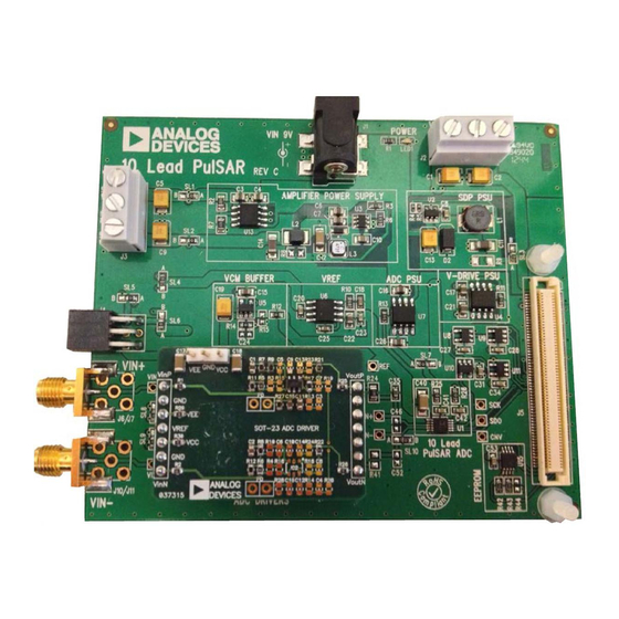
Page 4: Evaluation Board Hardware
UG-340 8-/10-Lead PulSAR User Guide EVALUATION BOARD HARDWARE SETTING UP THE EVALUATION BOARD Figure 27 shows the evaluation board schematic. The board Table 2. Table of Jumper Detail with Factory Default Setting consists of the ADC, U1, with a reference, U6 (ADR435), and Link Setting Function... -
Page 5: Evaluation Board Software
INSTALLING THE SOFTWARE The evaluation board software can be downloaded from the relevant product page on the Analog Devices website. Install the software prior to connecting the SDP board to the USB port of the PC. This ensures that the SDP board is recognized when it connects to the PC. - Page 6 UG-340 8-/10-Lead PulSAR User Guide Figure 6. Bar Showing Installation Progress Figure 9. Click Next > to Install the ADI SDP Drivers Figure 7. Installation Complete, Click Next >> to Complete and Finish Figure 10. Choose Install Location, Default Folder Shown The second part of the software installation is the drivers related to the SDP board.
-
Page 7: Board Operation/Connection Sequence
CONNECTED To run the program, take the following steps: Click Start > All Programs > Analog Devices > 8 & 10 Lead PulSAR ADCs. To uninstall the program, click Start > Control Panel > Add or Remove Programs > Analog Devices 8 &... -
Page 8: Running The Software Without Hardware
The software can run in standalone mode when no evaluation board hardware is connected to the USB port. Click Start > All Programs > Analog Devices > 8 & 10 Lead PulSAR ADCs. The software automatically seeks to find the hardware connected;... -
Page 9: Software Operation
8-/10-Lead PulSAR User Guide UG-340 SOFTWARE OPERATION When the software launches, the panel opens and the software looks for the hardware connected to the PC. The software detects the generic attached to the PC (see Figure 19). The product panel then launches. Figure 19. -
Page 10: Description Of User Panel
UG-340 8-/10-Lead PulSAR User Guide DESCRIPTION OF USER PANEL The following is the description of the user panel: File menu with choice of Load Data: load previously captured data Save Data as .tsv: save captured data in tsv (tab separated values) format for future analysis Figure 21. -
Page 11: Waveform Capture
8-/10-Lead PulSAR User Guide UG-340 WAVEFORM CAPTURE Figure 22 illustrates the waveform capture. The input signal is a 1 kHz sine wave. The waveform analysis reports the amplitudes recorded from the captured signal in addition to the frequency of the signal tone. Figure 22. -
Page 12: Ac Testing-Histogram
UG-340 8-/10-Lead PulSAR User Guide AC TESTING—HISTOGRAM Note that an ac histogram needs a quality signal source applied to the input J6/J10 connectors. Figure 23 shows the histogram The ac testing histogram tests the ADC for the code distribution for a 1 kHz sine wave applied to the ADC input. for the ac input, computes the mean and standard deviation, or Figure 23 shows the histogram results for the signal applied. -
Page 13: Dc Testing-Histogram
8-/10-Lead PulSAR User Guide UG-340 DC TESTING—HISTOGRAM and spurious-free dynamic range (SFDR). The data can also be displayed in the time domain. To perform an ac test, apply More commonly, the histogram is used for dc testing where the a sinusoidal signal to the evaluation board at the SMA inputs, user tests the ADC for the code distribution for dc input, computes J6/J10. -
Page 14: Summary Tab
UG-340 8-/10-Lead PulSAR User Guide SUMMARY TAB The Summary tab captures all the display information and provides them in one panel with a synopsis of the information including key performance parameters, such as SNR and THD. Figure 25. Summary Tab, Shows All Captured Windows Rev. -
Page 15: Save File
.tsv (tab separated values). navigate to find these example files. The default location for the example files is C:\Program Files\Analog Devices\8 & 10 Lead The user is prompted with a Choose or Enter Path of File box PulSAR ADCs\Example files. -
Page 16: Evaluation Board Schematics
UG-340 8-/10-Lead PulSAR User Guide EVALUATION BOARD SCHEMATICS Figure 27. 10-Lead Evaluation Board, ADC and Driver Rev. C | Page 16 of 31... -
Page 17: Added Figure 28; Renumbered Sequentially
8-/10-Lead PulSAR User Guide UG-340 Figure 28. 8-Lead Evaluation Board, ADC and Driver Rev. C | Page 17 of 31... - Page 18 UG-340 8-/10-Lead PulSAR User Guide Figure 29. Voltage Reference and Common-Mode Buffer Figure 30. Secondary Power Connector for Bench Supply Purposes Rev. C | Page 18 of 31...
- Page 19 8-/10-Lead PulSAR User Guide UG-340 Figure 31. On-Board Amplifier Power Supply, +7.5/−2.5 V Rev. C | Page 19 of 31...
- Page 20 UG-340 8-/10-Lead PulSAR User Guide Figure 32. SDP Power Supply Figure 33. ADC/V Power Supply DRIVE Rev. C | Page 20 of 31...
- Page 21 8-/10-Lead PulSAR User Guide UG-340 Figure 34. SDP Connector and Glue Logic Rev. C | Page 21 of 31...
- Page 22 UG-340 8-/10-Lead PulSAR User Guide Figure 35. Header Connectors, Optional Connectors for Possible Add-On Boards Rev. C | Page 22 of 31...
-
Page 23: Changes To Figure 36 Caption And Figure 37 Caption
8-/10-Lead PulSAR User Guide UG-340 Figure 36. 10-Lead Evaluation Board Silkscreen, Top Layer Figure 37. 10-Lead Evaluation Board, Layer 1 Rev. C | Page 23 of 31... -
Page 24: Changes To Figure 38 Caption And Figure 39 Caption
UG-340 8-/10-Lead PulSAR User Guide Figure 38. 10-Lead Evaluation Board, Layer 2 Figure 39. 10-Lead Evaluation Board, Layer 3 Rev. C | Page 24 of 31... -
Page 25: Changes To Figure 40 Caption
8-/10-Lead PulSAR User Guide UG-340 Figure 40. 10-Lead Evaluation Board, Layer 4 Rev. C | Page 25 of 31... -
Page 26: Added Figure 41 And Figure 42
UG-340 8-/10-Lead PulSAR User Guide Figure 41. 8-Lead Evaluation Board Silkscreen, Top Layer Figure 42. 8-Lead Evaluation Board, Layer 1 Rev. C | Page 26 of 31... -
Page 27: Added Figure 43 And Figure 44
8-/10-Lead PulSAR User Guide UG-340 Figure 43. 8-Lead Evaluation Board, Layer 2 Figure 44. 8-Lead Evaluation Board, Layer 3 Rev. C | Page 27 of 31... -
Page 28: Added Figure 45
UG-340 8-/10-Lead PulSAR User Guide Figure 45. 8-Lead Evaluation Board, Layer 4 Rev. C | Page 28 of 31... -
Page 29: Troubleshooting
8-/10-Lead PulSAR User Guide UG-340 TROUBLESHOOTING HARDWARE SOFTWARE To troubleshoot the hardware, take the following steps: To troubleshoot the software, take the following steps: If the software does not read any data back, do the Always install the software prior to connecting the hardware following: to the PC. -
Page 30: Changes To Table 5
UG-340 8-/10-Lead PulSAR User Guide PRODUCTS ON THIS EVALUATION BOARD Table 5. Product Ordering Model Sample Rate Resolution (Bit) Package Used on Evaluation Board AD7683BRMZ EVAL-AD7683SDZ 100 kSPS 8-Lead MSOP AD7684BRMZ EVAL-AD7684SDZ 100 kSPS 8-Lead MSOP AD7685BRMZ EVAL-AD7685SDZ 250 kSPS 10-Lead MSOP AD7686BRMZ EVAL-AD7686SDZ... - Page 31 By using the evaluation board discussed herein (together with any tools, components documentation or support materials, the “Evaluation Board”), you are agreeing to be bound by the terms and conditions set forth below (“Agreement”) unless you have purchased the Evaluation Board, in which case the Analog Devices Standard Terms and Conditions of Sale shall govern. Do not use the Evaluation Board until you have read and agreed to the Agreement.
- Page 32 Mouser Electronics Authorized Distributor Click to View Pricing, Inventory, Delivery & Lifecycle Information: Analog Devices Inc. EVAL-AD7988-5SDZ EVAL-AD7946-PMDZ EVAL-AD7687-PMDZ EVAL-AD7688-PMDZ EVAL-AD7988-5-PMDZ EVAL-AD7980-PMDZ EVAL-AD7691-PMDZ EVAL-AD7685-PMDZ EVAL-AD7686-PMDZ EVAL-AD7982-PMDZ EVAL-AD7942-PMDZ EVAL-AD7983-PMDZ EVAL-AD7690-PMDZ EVAL-AD7984-PMDZ EVAL-AD7693-PMDZ EVAL-AD7684SDZ...
Need help?
Do you have a question about the PulSAR AD7685 and is the answer not in the manual?
Questions and answers