
Related Manuals for Dräger Medical Zeus


Summary of Contents for Dräger Medical Zeus
- Page 1 Technical Documentation Zeus Anesthetic workstation Revision 3.0 5133.001 9036190 Because you care...
-
Page 3: Table Of Contents
General Symbols and Definitions Notes Abbreviations and Definitions Function Description General information about Zeus Intended use (summary from the Instructions for Use manual) ..........9 Product classification ......................9 Protection classes ........................9 Brief description of the system ..................... 10 Anaesthetic Gas Box General introduction ...................... - Page 4 Contents DIVA metering module ......................33 Zeus Gas Measuring Module (GMZ) General introduction ......................39 Patient Gas Analyzer (PGA) General ..........................41 IRIA ............................41 ILCA 2 ........................... 43 Servomex or Pato ........................ 44 System Gas Analyser (SGA) General introduction ......................49 ILCA ............................
- Page 5 Contents Hermes Computer with Monitor 13.1 General ..........................73 13.2 CPCI computer ........................73 13.3 Display screen ........................74 Maintenance Procedures Water trap Replacement interval ......................79 Replacing or draining the water trap ..................79 Blower spindle Replacement interval ......................81 Replacing the blower spindle ....................
- Page 6 Contents Flow sensor “SpiroLife” in the breathing system Replacement interval ......................93 Replacing the “SpiroLife” flow sensor ................... 93 Sampling-gas return-line filter Replacement interval ......................95 Replacing the filter ........................ 95 Sintered-metal filters of the CS connections Replacement interval ......................97 Replacing the sintered-metal filters ..................
- Page 7 Contents Schematics and Diagrams Schematics and diagrams Annex Technical Documentation acc. to EMV standard IEC/EN 60601-1-2: 2001 Test List Spare Parts Catalogue...
- Page 8 Contents...
- Page 9 General...
- Page 11 Zeus General Symbols and Defini- tions WARNING A WARNING statement provides important information about a poten- tially hazardous situation which, if not avoided, could result in death or serious injury. CAUTION A CAUTION statement provides important information about a potentially...
- Page 12 General Zeus Know-how contained in this Technical Documentation is subject to ongoing change through research and development and Dräger Medical reserves the right to make changes to this Technical Documentation without notice. NOTE Unless otherwise stated, reference is made to laws, regulations or stan- dards (as amended) applicable in the Federal Republic of Germany for equipment used or serviced in Germany.
- Page 13 EEPROM Electrically Eraseable Programmable Read Only Memory Flash-ROM Flash Read Only Memory Gas Measuring module Zeus HERMES Display and operating unit of Zeus ILCA Infrared Low Cost Analyzer IRIA Infrared Rapidly Identifying Analyzer Management Information Base Mid Infrared Range MISO...
- Page 14 Function Description Zeus 5133.001...
- Page 15 Function Description...
-
Page 17: General Information About Zeus
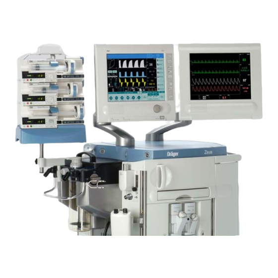
General information about Zeus Figure 1 View of the Zeus anesthesia workstation Intended use (sum- Zeus is an integrated anesthesia workstation for inhalation and intravenous mary from the anesthesia. Zeus is used Instructions for Use – in operating rooms as well as in induction and recovery rooms manual) –... -
Page 18: Brief Description Of The System
Dräger syringe pumps for intravenous anesthesia 1.4.1 Configuration The Zeus anesthesia workstation can be subdivided into the display and con- trol unit HERMES and the anesthetic gas box (A-Box). HERMES is a PC based system for display and control of the A-Box or other connected front-end units, such as the parameter box for measurement of hemodynamic values. - Page 19 Zeus General Figure 2 System overview 5133.001...
- Page 20 General Zeus 5133.001...
-
Page 21: Anaesthetic Gas Box
Zeus Function Description Anaesthetic Gas General introduction The anaesthetic gas box comprises the trolley and the housing of the Zeus. Apart from the monitor, it includes all the components required to operate the functions of the Zeus. They include: –... - Page 22 Function Description Zeus 5133.001...
-
Page 23: Pcb Box
Function Description PCB Box The PCB box is a housing system for PCBs in the Zeus. It principally com- prises the Transfer PCB, which performs the function of a motherboard. The Transfer PCB accommodates additional PCBs: the standard Zeus PCBs as well as PCBs for later options. -
Page 24: Verona Pcb
3.3 V supply (Brown-Out monitor). VERONA PCB 3.2.1 Purpose The VERONA PCB is required in the ZEUS to control the ventilator and to interface to the CAN bus. For this, a microcontroller system based on the PPC555 is used. 3.2.2... - Page 25 Zeus Function Description Figure 4 Block diagram of the VERONA PCB The voltage supply is fed in via an EMC-filter and monitored by the controller. The controller PPC555 has an internal RAM which can be optionally battery- buffered. The following operating voltages are generated on the PCB: –...
-
Page 26: Vent Power Pcb
Function Description Zeus are delivered by the motor electronics. The motor temperature is evaluated, as are the other temperature sensors. 6 LEDs are provided for output of sta- tus signals. The following LEDs are interesting for service work: – 12 V supply voltage = LED V405 –... -
Page 27: External Flow Pcb
Zeus Function Description The supply voltage for the TurboVent is externally stabilised in the power supply unit to 48 V and has a current limit of 3 A. An external 68000 uF capacitor is included to deal with the high peak currents of the motor. - Page 28 The “Alveon” flow sensor is based on the principle of a filament anemometer principle (Figure 7). In conjunction with the Zeus anaesthetic workstation, the measur- ing wire (2) is used for compensation of the breathing gas, the measuring wire (3) for “flow measurement” and the measuring wire (5) with the shading (4) for detecting the direction of flow.
- Page 29 Zeus Function Description Figure 7 “Alveon” flow sensor layout 5133.001...
- Page 30 Function Description Zeus 5133.001...
-
Page 31: Cs Module
In the gas-carrying component of the CS module the compressed gases are reduced as required and fed to the relevant assemblies. Gas supply 4.2.1 Feed-in of compressed The following description relates to the extract from the Zeus gas flow dia- gases with CS gram (Figure 5133.001... - Page 32 Function Description Zeus Figure 9 Extract, gas flow diagram, gas inlet block The compressed gases O2, N2O and AIR are fed in via the CS to the gas supply block of the CS module. The description is based on the example of O2, and is identical for N2O and AIR.
- Page 33 Zeus Function Description system is supplied with an O2 safety flow adjustable between 0.4 and 12 L/min. As an option, a 0 to 10L/min regulated O2 outlet for an O2 flowme- ter is installed. 4.2.2 Feed-in of compressed As an option, it is also possible to connect a maximum of 2 reserve gas cylin- gases with reserve gas ders.
-
Page 34: Dagmar Mixed Gas Metering Unit
Function Description Zeus The PCB the CS and reserve gas cylinder pressure sensor signals and con- trols the 8 indicator LEDs on the control panel of the main monitor. As long as the mains power is present, the 8 LEDs are supplied with a permanent 24 V (ULED). - Page 35 Zeus Function Description Figure 11 Extract from Zeus gas flow diagram, Dagmar valve block One branch meters oxygen. It consists of the O2 switching valve (63), the O2 supply pressure sensor (64) and 5 digital valves (54) to (58) with downstream flow control valves for mixing.
- Page 36 Function Description Zeus Figure 12 Block diagram of the DAGMAR PCB The operating voltage for the sensors (12 V) and the processor system (5 V) is derived from the supply voltage. The input voltage is monitored by the pro- cessor system.
-
Page 37: Diva Anaesthetic Metering Unit
Zeus Function Description DIVA Anaesthetic Metering Unit Figure 13 Supply module with 1 connected metering module General introduction 5.1.1 Purpose The DIVA anaesthetic metering unit meters volatile anaesthetic. It comprises the supply module and up to 2 metering modules. The supply module is built into the anaesthetic gas-box. -
Page 38: Diva Supply Module
Function Description Zeus Figure 14 Optical and electrical interfaces DIVA supply module The supply module is not anaesthetic-specific. It holds the metering modules and provides the interface to the anaesthetic machine. The supply module principally comprises 2/2-way valves to control the propellant gas and the saturated vapour. - Page 39 Zeus Function Description Figure 15 Supply module gas flow diagram For safety reasons (risk of explosion), the propellant gas used is AIR. The propellant gas flows through the non-return valve (30) and the volume (170 mL) to the pressure reducer (71). There the pressure is stabilised at 2.4 bar relative.
- Page 40 Function Description Zeus The distributor block heater (4), the mixing chamber heater (88) and the satu- rated vapour line heater (61) prevent anaesthetic condensing in the outlet of the supply module. The heat output is regulated with the temperature sensors (65 and 66) and the temperature sensor of the mixing chamber heater.
-
Page 41: Diva Metering Module
Zeus Function Description The actuation valves for the left and right side metering modules are con- trolled by a valve driver. When the microcontroller is in Reset mode the power is cut to all valves. To minimise the power loss from the valves, the voltage is switched down from 18 V to 7 V by means of an integrated circuit (step-down regulator) once the valves have been actuated. - Page 42 Function Description Zeus Figure 17 Metering module gas flow diagram When the metering module is connected and locked in place, the closure valves (25) and (72) are mechanically opened. The module detector (38) detects the connected and locked metering module. The pressure sensor (21) measures the input pressure of the propellant gas.
- Page 43 Zeus Function Description The injection valve (9 and 8) injects a defined quantity of liquid anaesthetic into the evaporator chamber (7) as specified. In the evaporator chamber (7) the liquid anaesthetic is converted into saturated vapour (100% anaesthetic). The evaporator chamber heater (68) is regulated by way of the temperature sensor (69).
- Page 44 Function Description Zeus Figure 18 Block diagram of the Metering Module PCB The valves are controlled by a valve driver. When the microcontroller is in Reset mode the power is cut to all valves. To minimise the power loss from the valves, the voltage is switched down from 18 V to 7 V by means of an integrated circuit (step-down regulator) once the valves have been actuated.
- Page 45 Zeus Function Description The Metering Module PCB has a Debug interface which can be addressed optionally by way of a plug connector or via an IR transceiver. Another IR-interface (Safety) receives pulses from the supply module. If those pulses are not received, e.g. because of an error in the supply module, all the valves of the metering module are set to a safe state.
- Page 46 Function Description Zeus 5133.001...
-
Page 47: Zeus Gas Measuring Module (Gmz)
General introduction 6.1.1 Purpose The function of the Zeus gas measuring module (GMZ) is to measure the gases O2, N20 and CO2 and the anaesthetics Desflurane, Enflurane, Hal- othane, Isoflurane and Sevoflurane for the purposes of monitoring. Two inde- pendent systems are used for this. One is a closed-loop patient-local system which taps the measured values directly at the Y-piece. - Page 48 Function Description Zeus and the component assembly: – System gas analyser (SGA) with – ILCA – OxyTrace – Dräger water trap 5133.001...
-
Page 49: Patient Gas Analyzer (Pga)
Zeus Function description Patient Gas Analyzer (PGA) General Figure 20 PGA block diagram (example GMZ) 7.1.1 Intended use The patient gas analyzer is a complete scavenging gas analysis system for measurement of the patient gas at the Y-piece. It detects and measures the gases O2, N2O and CO2 present at the Y-piece and the anesthetics Desflu- rane, Enflurane, Halothane, Isoflurane and Sevoflurane. - Page 50 Function description Zeus Figure 21 IRIA module without sensor 7.2.1 Intended use IRIA is a gas measuring module for N2O, CO2 and the anesthetic gases Hal- othane, Enflurane, Isoflurane, Desflurane and Sevoflurane. The gas measur- ing module can automatically recognize the anesthetic in use.
-
Page 51: Ilca 2
Zeus Function description wavelengths from the broadband infrared radiation in the near (NIR) and mid (MIR) ranges. Those wavelengths are use to measure CO2/N2O (NIR approx. 3 μm) and anesthetic gas (MIR approx. 9 μm). 7.2.4 Function There are a total of 8 filters on the filter wheel: –... -
Page 52: Servomex Or Pato
Function description Zeus Servomex or Pato The patient gas analyzer may be equipped with different oxygen sensors. The “Servomex” oxygen sensor is used in the GMZ. The “Pato” oxygen sen- sor is used in the GMZ 2. Both oxygen sensors measure the patient's O2 concentration at the Y-piece. - Page 53 Zeus Function description Figure 23 Schematic of Servomex 7.4.2 Pato The oxygen sensor measures the patient's O2 concentration at the Y-piece. 7.4.2.1 Measurement principle The PATO O2 sensor uses the fact that oxygen molecules have a stronger paramagnetic characteristic (attracted to a magnetic field) than the molecules of other gases.
- Page 54 Function description Zeus 7.4.2.2 Configuration PATO O2 sensor The PATO O2 sensor consists of the PATO SA MC PCB and PATO SA SH PCB, and the sensor head. The assemblies are contained in a housing. Com- munication with the medical product takes place via an RS232 interface (port).
- Page 55 Zeus Function description Sensor element The sensor element has a heating element and a thermoelement. Figure 27 PATO sensor element Table 3 Legend to Figure 27 Item Name Measurement compartment (part of the cuvette) Heating element and thermoelement assembly Gas channel (part of the cuvette) 7.4.2.3 Function...
- Page 56 Function description Zeus Figure 28 Block diagram 5133.001...
-
Page 57: System Gas Analyser (Sga)
Zeus Function Description System Gas Analy- ser (SGA) General introduction Figure 29 Connection diagram 8.1.1 Purpose The system gas analyser is a complete scavenging gas analysis system for measurement of the gas concentration in the inspiratory branch. It measures O2, N2O and CO2 as well as the anaesthetics Desflurane, Halothane, Isoflu- rane and Sevoflurane. -
Page 58: Ilca
Function Description Zeus ILCA Figure 30 ILCA module complete 8.2.1 Purpose ILCA is a gas measuring module for N2O, CO2 and the anaesthetic gases Halothane, Enflurane, Isoflurane, Desflurane and Sevoflurane. ILCA con- forms to the measurement accuracy specified by ISO-standard. - Page 59 Zeus Function Description The module rack of the ILCA module contains 4 additional PCBs with the fol- lowing functions: – AMO FLOW ILCA PCB - Control of the pump and the zero calibration solenoid. A serial EEPROM stores the necessary data such as the serial number, hardware/software revision, control parameters etc.
- Page 60 Function Description Zeus Figure 31 Principle of multi-channel detector with IR filters Table 4 Legend to Figure 31 Item Name Sensor window Infrared light CO2 sensor chip with infrared filter Reference sensor chip with infrared filter Beam splitter (prism) Anaesthetic gas sensor chip...
- Page 61 Zeus Function Description A pneumatic low pass, comprising the volume C1 and the flow control valve R1, minimises the pressure surges generated by the pump (Figure 32). Figure 32 Block diagram of the ILCA In substitution for a flowmeter, the pressure is measured with a differential pressure sensor upstream and downstream of the flow control valve.
-
Page 62: Oxytrace
Purpose The OxyTrace oxygen measuring cell forms part of the system gas analyser of the Zeus gas measuring module and performs the function of recording the O2 concentration in the inspiratory branch or in the fresh gas. The measuring mode is switched by a solenoid valve. - Page 63 Zeus Function Description A working electrode and a counter-electrode are housed in an electrolyte- filled sensor housing. The electrolyte chamber is isolated from the gas-con- ducting section of the sensor by a diffusion barrier. At the working electrode, which has a potential against the counter-electrode, the oxygen diffused through the barrier is reduced.
- Page 64 Function Description Zeus 5133.001...
-
Page 65: Power Supply Unit
Function description Power supply unit General 9.1.1 Purpose The power supply unit of the Zeus supplies all the electrical components with the required voltages and currents. It has an uninterruptible power supply with rechargeable batteries. 9.1.2 Features The power supply unit has the following features: –... -
Page 66: Output Voltages
Hermes computer Apollo module Transfer PCB (Power) Transfer PCB (Signals) Emergency-off button On button (Prod./Service) DAGMAR PCB Hermes monitor DIVA ZEUS motherboard Blower capacitor Apollo module (12 V/20 W), 3 A fast DIANA (24 V/12 W), 3 A fast 5133.001... -
Page 67: Uninterruptible Power Supply
The power supply unit has an uninterruptible power supply. In the event of a mains power failure the Zeus continues operating for approximately 30 min- utes in normal mode under battery power. Because of their size, the batteries are fitted in the base plate. - Page 68 Function description Zeus 5133.001...
-
Page 69: Dräger Water Trap
Zeus Function Description Dräger Water Trap Figure 35 Principle of operation of the Dräger water trap The Dräger water trap has two Goretex™ membranes which protect the channel to the cuvette (180 ml/min) as well as the bypass branch (20 ml/min) against incursion of damp. - Page 70 Function Description Zeus 5133.001...
-
Page 71: Blower
Zeus Function Description Blower Figure 36 Blower complete 11.1 General introduction 11.1.1 Purpose The blower is designed for use in closed systems. Its function is to generate the pressure required for ventilation. In order to improve the mix of gases in the system the blower generates a circulatory flow. - Page 72 Function Description Zeus Figure 37 Breathing system, simplified view The blower has the following properties: – The patient gas carrying components can be sterilised at 134 degrees C in hot steam. An exception to this is the blower spindle. It is protected by the filter and is replaced every 2 years.
- Page 73 Zeus Function Description Figure 38 Blower sectional diagram Table 7 Legend to Figure 38 Item Designation Electric motor Magnetic fluid seal Blower wheel Blower inlet Blower outlet Bellows Blower spindle Foam Felt disc (coupling) Needle coupling Low noise based on absorption of vibration by magnetic fluid seal (2), silicone (6) and foam (8).
- Page 74 Function Description Zeus 5133.001...
-
Page 75: Breathing System
Zeus Function Description Breathing System Figure 39 Breathing System 12.1 General introduction 12.1.1 Purpose The function of the breathing system is to control the gas flow and the pres- sure in the breathing system as specified. Gas breathed back into the breath- ing system has CO2 removed from it by means of a soda lime absorber and is re-used. -
Page 76: Components In The Breathing System And Their Functions
Function Description Zeus The breathing system is adapted onto the side of the Zeus housing at the pneumatic interface. The interface provides the mechanical, pneumatic and electrical connections to the anaesthetic gas box. It also accommodates the Valve Control PCB and the Pressure/Flow PCB. Two inductive senders at the connection point signal inadequate locking of the breathing system. - Page 77 Zeus Function Description Item Name Function Feed into anaesthetic gas Scavenging of surplus gas scavenging system Non-return valve of anaes- Inflates manual breathing bag by thetic gas scavenging system means of spring force. Prevents breathing-back from anaesthetic gas scavenging system Closed valve Works as an On/Off valve.
-
Page 78: Function
Function Description Zeus Item Name Function Inspiration-side flow sensor Regulation of the inspiratory flow under constant-flow ventilation. Measurement of the tidal volume under constant-volume ventila- tion. Regulation of the circulatory flow in expiration. Breathing system safety valve Limits the max. pressure in the system and thus at the patient. - Page 79 Zeus Function Description The blower (21) is pressure-regulated and speed-limited. It conveys gas from the breathing bag (27) through the absorber (22) and the non-return valve (19) into the patient's lung (13). The inspiratory pressure is regulated with the blower and the proportional valve (6).
- Page 80 Function Description Zeus 5133.001...
-
Page 81: Hermes Computer With Monitor
13.1.1 Purpose The Hermes system processes and visualises the parameters and process data of the Zeus anesthetic workstation. It also provides input and output interfaces for operator control of the Zeus. The Hermes system comprises a Windows-based CPCI computer with up to three display units. -
Page 82: Display Screen
Function description Zeus Item Name assigned to Digital video interface 1 DVI for main monitor Ethernet port 2 Apollo module USB port USB for auxiliary monitor Printer port Printer Floppy disk drive Serial port (COM) 2 free PS/2 Mouse/keyboard free... - Page 83 “DC Out” output on the CPCI computer. – Screen In: By way of this port the monitor and supply system of the Zeus exchange information, such as on the readiness of the power and pipe- line supply networks, the battery charge condition and on/off messages for the overall system.
- Page 84 Function description Zeus 5133.001...
-
Page 85: Maintenance Procedures
Maintenance Procedures... -
Page 87: Water Trap
2); remove the syringe and dispose it accord- ing to applicable regulations. Figure 2 Sucking out the water 4. Insert the water trap into the holder until it engages perceptibly. 5. Perform a functional check according to the Zeus test instructions. 5133.001... - Page 88 Maintenance procedures Zeus 5133.001...
-
Page 89: Blower Spindle
8. Refit the blower spindles in the reverse order of their removal. 9. Attach the label (month and year of the blower replacement) to the hous- ing of the blower drive. 10. Perform the ventilation modes function tests as per Zeus test document. 5133.001... - Page 90 Maintenance procedures Zeus 5133.001...
-
Page 91: Filter Mat In The Power Supply Unit
Replacement inter- For replacement intervals of the filter mat, refer to the Zeus Instructions for Use manual. Location The power supply unit is located on the side of the Zeus which holds the breathing system (Figure 4, dashed frame). Figure 4... - Page 92 2. Remove the frame. 3. Replace the filter mat. 4. Check the fan for proper functioning. 5. Refit the plastic covers using the reverse method of that used for removal. 6. Perform a functional check according to the Zeus test instructions. 5133.001...
-
Page 93: Filter Mat In The Gmz
Risk of short circuiting during disassembly. In order to avoid short-circuits in the device during disassembly of parts or assemblies, shut down the Zeus, set the power switch to the “OFF” posi- tion, and disconnect the Zeus from the power supply. - Page 94 Maintenance procedures Zeus Figure 7 Filter mat (arrow) in the GMZ 3. Refit the plastic covers using the reverse method of that used for removal. 4. Perform a functional check according to the Zeus test instructions. 5133.001...
-
Page 95: Removing/Fitting The Breathing System
1. Unscrew the 5 screws marked with arrows in Figure Figure 8 Plate fixing screws 2. Remove the plate. 3. Refit the breathing system using the reverse order of that used for removal. 4. Perform a functional check according to the Zeus test instructions. 5133.001... - Page 96 Maintenance procedures Zeus 5133.001...
-
Page 97: Diaphragm Mounts In The Breathing System
Diaphragm mounts in the breathing sys- Replacement inter- Refer to the Zeus Instructions for Use manual for the replacement intervals of the flow, Spont, and Closed valve diaphragm mounts. Removing the 1. Remove the breathing system as described in the chapter... - Page 98 Maintenance procedures Zeus Figure 10 Diaphragm mount location hole NOTE Observe the preferred position of the diaphragm mount. The location holes for the diaphragm mounts have a large gap on each side (see arrows in Figure 10). To keep the flow resistance low, these gaps...
-
Page 99: Fitting The Breathing System
6. Fit the new diaphragm mount into the breathing system making sure it is aligned properly (preferred position). Fitting the breathing 1. Fit the breathing system as described in the chapter Maintenance Proce- system dures, Removing/Fitting the Breathing System. 2. Perform a functional test as per Zeus test documentation. 5133.001... - Page 100 Maintenance procedures Zeus 5133.001...
-
Page 101: Flow Sensor "Spirolife" In The Breathing System
Flow sensor “SpiroLife” in the breathing system Replacement inter- For the replacement interval of the “SpiroLife” flow sensor, refer to the Zeus Instructions for Use manual. Replacing the 1. Unscrew the inspiratory hose connection (← ) and/or the expiratory hose “SpiroLife”... - Page 102 Maintenance Procedures Zeus 5133.001...
-
Page 103: Sampling-Gas Return-Line Filter
3. Disconnect the filter (shown by an arrow) from the tubes and replace it with a new one. 4. Refit using the reverse order of that used for removal. 5. Perform a functional test as per Zeus test documentation. 5133.001... - Page 104 Maintenance Procedures Zeus 5133.001...
-
Page 105: Sintered-Metal Filters Of The Cs Connections
Sintered-metal filters of the CS connec- tions Replacement inter- For replacement intervals of the sintered-metal filter, refer to the Zeus Instructions for Use manual. Replacing the sin- The following steps can be carried out with the CS module fitted. tered-metal filters... - Page 106 Maintenance procedures Zeus Figure 15 Sintered filter 4. Screw in the new sintered-metal filter of the O2 NIST connection hand- tight. 5. Check that the O-ring on the NIST connection is undamaged and replace it as necessary. 6. Screw in the two fixing screws of the NIST connection for O2. Make sure the O-ring is not trapped.
-
Page 107: Pressure Regulators On The Gas Inlet Block
Location In order to replace the pressure regulators, you need to remove the CS mod- ule. The CS module is fitted on the side of the Zeus on which the reserve gas cylinders are also located. Figure 17 CS module fitting location 10.3... - Page 108 3. Withdraw the CS module far enough for the connectors and tubes to be easily accessible but not so far as to pull it out of the Zeus. 4. Cut the heat-shrink tubing at the power switch in the area of the lock nut,...
- Page 109 7. Unplug the fan connector from the CS Pressure PCB (on the left side of the CS module). 8. Detach the central connector to the Zeus on the DAGMAR PCB (on the right side of the CS module). 9. Withdraw the CS module completely from the Zeus.
-
Page 110: Replacing The Pressure Regulators
Maintenance procedures Zeus Figure 21 CS module complete 10.4 Replacing the pres- 1. Unplug the connectors of the two sockets to connect the high-pressure sure regulators sensors on the CS Pressure PCB and take the cable out of the cable clamp. - Page 111 (1 = inlet, 2 = outlet). Figure 23 Predominant position of the pressure regulators 6. Before the CS module is fitted in the Zeus, the pressure regulator must be adjusted as per the test document. To do so, pull up the circular cap of the pressure regulator (to unlock it) and adjust the pressure by turning the cap.
- Page 112 Maintenance procedures Zeus 5133.001...
-
Page 113: Batteries Of The Uninterruptible Power Supply
Zeus, set the power switch to the “OFF” posi- tion, and disconnect the Zeus from the power and gas supplies. 1. On the rear of the Zeus underneath the trolley, detach the PE conductor and the connector (Figure 24/2) from the rechargeable batteries' drawer. - Page 114 Maintenance procedures Zeus 4. Disconnect the connecting cables (Figure 25/2). Figure 25 Connecting the rechargeable batteries 5. Unscrew the leads (Figure 25/1) and remove the rechargeable batteries. CAUTION Overheating of the rechargeable batteries. In order to avoid overheating the rechargeable batteries during charging, the charging cycle is controlled by a temperature sensor.
- Page 115 Schematics and Diagrams...
- Page 117 Zeus Schematics and diagrams 5133.001...
- Page 118 Schematics and diagrams Zeus 5133.001...
- Page 119 Zeus Schematics and diagrams 5133.001...
- Page 120 Schematics and diagrams Zeus 5133.001...
- Page 121 Zeus Schematics and diagrams 5133.001...
- Page 122 Schematics and diagrams Zeus 5133.001...
- Page 123 Zeus Schematics and diagrams 5133.001...
- Page 124 Schematics and diagrams Zeus 5133.001...
- Page 125 Zeus Schematics and diagrams 5133.001...
- Page 126 Schematics and diagrams Zeus 5133.001...
- Page 128 Annex Technical Documentation acc. to EMV standard IEC/EN 60601-1-2: 2001 Test List Spare Parts Catalogue...
- Page 130 ® Other equipment which can be used adjacent to or stacked with this device are listed in Zeus List of Acces- sories or if a EC Declaration of Compatibility is available by Dräger Medical.
- Page 131 ® The Zeus Anaesthesia Workstation System is intended for use in the electromagnetic environment speci- ® fied below. The user of the Zeus Anaesthesia Workstation System should assure that is used in such an environment. Immunity IEC 60601-1-2 test level...
- Page 132 Recommended separartion distances Recommended separation distances between portable and mobile RF-Telecommunication devices ® and the the Zeus Anaesthesia Workstation System max. 3 V/m dis- 1 V/m dis- Hint tance* (m) tance* (m) EIRP 0.001 0.06 0.17 0.003 0.10 0.30 0.010 0.18...
- Page 134 Test list (TL) Zeus This test list can be processed with standard commercially available test aids and tools, but does not replace the inspections and maintenance work carried out by the manufacturer Dräger Medical AG & Co. KGaA. Notes on field of application: Tests marked with the "check" symbol are listed in the test report.
- Page 135 Function of O2 flush 3.12 Blower 3.13 DIVA metering module 3.14 Power supply unit 3.15 Zeus power-on test 3.16 Hemodynamics monitoring (if fitted) 3.17 Gas measurement module Zeus (GMZ) 3.18 Ventilation modes 3.19 Unit handover Zeus 2005-03 Released - page 2 -...
-
Page 136: Unit Configuration
Unit configuration Serial numbers [______txt] 1.1.1 Zeus The serial number is located on the rear panel of the Zeus. 1.1.2 Breathing-system housing [______txt] The serial number is located on the edge of the housing. [______txt] 1.1.3 Compact breathing system cover The serial number is located on the edge of the cover. -
Page 137: Software Versions
Germany, whereas the ÖVE-MG 751 law is applicable in Austria). Some specifications may vary in accordance with the test equipment used. The Zeus conforms to the requirements of protection class I With Alveon sensor it conforms to type BF. -
Page 138: Visual Check
If a test results in a value of 0.0 microamperes, check whether it is due to a measurement error. Most of the times it is caused by incorrect operation of the test instruments. [_______OK] Visual check Switch off the Zeus. Pull the power plug. Check the following parts for possible damage: Mains connecting cable including cable-strain relief. -
Page 139: Electrical Safety To Vde 0751
Enter the higher test value in the test report. Test value including power cable: R less than/equal to 0.3 ohms. Using the test probe of the tester measure the resistance to the metal parts of the Zeus listed above. if available: Scan the pusher rods of the Dräger Module DPS (syringe pumps) using the test probe. - Page 140 Each initial value must be transferred to a new test report. 2.3.3.8 Subsequent measurement of the AUX/HEMO3 connection [______μA] The deviation between the subsequent measurement and the initial value must be within permissible tolerance. [OK] Zeus 2005-03 Released - page 7 -...
-
Page 141: Electrical Safety To Iec
Connect the black conductor of the test cable to the metal parts of the ceiling pendant/wall mounting. Using the test probe of the tester measure the resistance to the metal parts of the Zeus listed above. - Page 142 The patient leakage current test must be carried out with reversed and non-reversed power plug. Enter the highest value. This test can be implemented internally on most of the testers. NOTE: Make sure that power supply leads, accessories and system configuration correspond to the Zeus 2005-03 Released - page 9 -...
- Page 143 Test value: less than/equal to 100 μA [______μA] 2.4.5.4 Patient leakage current S.F.C. reversed (single fault condition, PEN conductor interrupted, power plug reversed) Test value: less than/equal to 500 μA 2.4.6 AUX/HEMO2 connection Interconnect the AUX/HEMO2 connection pins. Zeus 2005-03 Released - page 10 -...
-
Page 144: Function And Condition Test
Input test Precondition: DIVA metering module is not plugged in. Zeus is switched off. To detect possible device faults at an early stage, this step tests whether the self-test was completed without error. Upgrade and install complete compact breathing system. -
Page 145: Accompanying Documents
[OK] Read the check list. Power-on test is run through without error. [OK] Zeus is in ventilator standby mode. [OK] Open the service window, password "8090". Select the service window tab "System Info". Read the software versions and enter them in the report under test item 1.3. -
Page 146: Bronchial Suction Device (If Fitted)
Set vacuum switch to "Full Capacity" position unit P-vacuum is constant. Pstat = -0.5 bar to -0.95 bar [OK] Set the vacuum switch to "OFF" position. Pressure drop within 1 minute < 50 mbar. Zeus 2005-03 Released - page 13 -... -
Page 147: Breathing System
Read off flow from flowmeter block. The flow is between 8.1 L/min and 9.9 L/min. [OK] Remove the test set-up. Breathing system Precondition: DIVA metering module is not plugged in. The compact breathing system has been removed. Zeus 2005-03 Released - page 14 -... - Page 148 Build up pressure with the hand pump until the mechanical safety valve (3.16) opens. Read value of the digital manometer. The opening pressure must be between 75 hPa and 0.95 hPa. The test set-up is also used for the pressure gauge test. Zeus 2005-03 Released - page 15 -...
-
Page 149: Ups Test
Disconnect the Zeus power plug from the mains power supply and start the stopwatch. Note: In the battery capacity test, the Zeus must be operated for 30 minutes without mains power. During this time you can continue with the other tests. After 30 minutes the mains power must be restored. - Page 150 3.8.3 Downstream pressure test Close the high-pressure cylinders. Disconnect the connecting tube of the high-pressure regulator being tested from the Zeus and connect it to a pressure gauge (measuring range 10 bar). Open the high-pressure cylinder. Read the downstream pressure on the pressure gauge.
- Page 151 The O2 pressure reading corresponds to the internal pressure of the O2 high-pressure cylinder (maximum deviation 10%). The O2 high-pressure LED on the Zeus front lights green. [OK] The AIR pressure reading (if available) corresponds to the internal pressure of the AIR high-pressure cylinder (maximum deviation 10%).
-
Page 152: External O2 Flowmeter (If Fitted)
[_______OK] External O2 flowmeter (if fitted) Connect the Zeus to the O2 pipeline supply (the other pipeline supply must not be connected). Open the fine control valve of the external O2 flowmeter. The float of the external O2 flowmeter ascends. -
Page 153: Power Supply Unit
[_______OK] 3.14 Power supply unit [Check condition] 3.14.1 Power failure alarm [_______OK] Select any ventilation mode on the Zeus. Pull the power plug. A visual and an audible alarm are triggered. [_______OK] 3.15 Zeus power-on test Precondition: DIVA metering module is not plugged in. -
Page 154: Hemodynamics Monitoring (If Fitted)
Set the ECG simulator "phantom" to a frequency of 75. 3.16.1.1 ECG display [_______OK] HR is 70 to 90 bmp. [OK] The heart symbol flashes on the Zeus screen and the pulse tone is generated for each QRS complex. [OK] Peaks are displayed for each QRS complex. [OK] [_______OK] 3.16.1.2... - Page 155 [_______OK] 3.16.1.3 Alarm function Set the following alarm limits on the Zeus display: HR upper limit: 110 bpm HR lower limit: 40 bpm Alarm: ON The following alarms must be displayed: HR = 120 to 0.140 bpm The HR values flashes and the color changes.
- Page 156 Your current blood pressure values are displayed. [OK] If necessary, repeat the measurement making sure the cuff is positioned properly. 3.16.4 connect the HemoMed POD to the Zeus. [_______OK] 3.16.4.1 Zero calibration of the sensors Vent all existing IBP sensors.
-
Page 157: Gas Measurement Module Zeus (Gmz)
Precondition: DIVA metering module is not plugged in. Gas supply is connected. Zeus has been switched on for 15 minutes and is in "Running Mode": (Man/Spont, auto metering, 100% O2, 2 L/min, no anesthetic gas, Y-piece connected). [_______OK] 3.17.1... -
Page 158: Ventilation Modes
3.17.3 CO2 measurement of the PGA (ServoMex) Precondition: DIVA metering module is not plugged in. Zeus is switched on and in "Running Mode". Disconnect the sampling tube from the Alveon sensor. Breathe into the sampling tube. CO2 value is displayed. - Page 159 [OK] Close cylinders. Connect pipeline supply. 3.18.4 Volume Mode (const. Flow) [_______OK] Switch Zeus to "Volume Mode mode (const. Flow)“. Select the following parameters: PMAX: 50 hPa VT: 800 mL Freq: 12/min Ti : Te = 1 : 2 TPAUSE:TINSP: 20 % PEEP: 10 hPa Press the "Adjust alarm limits"...
-
Page 160: Unit Handover
After about 10 breaths check the following measured values: PEEP = 8 hPa to 12 hPa [OK] VT = 0.74 L/min to 0.86 L/min [OK] Switch Zeus to standby. 3.18.5 Control loops test [_______OK] 3.18.5.1 Insp. O2 Insp. O2 = 25%,... - Page 161 μA 1. 1 Serial numbers 2. 4. 2. 5 Earth leakage current N.C. reversed (IEC) μA 1. 1. 1 Zeus 2. 4. 2. 6 Earth leakage current N.C. reversed (UL) μA 1. 1. 2 Breathing-system housing 2. 4. 2. 7 Earth leakage current S.F.C. reversed (IEC) μA...
- Page 162 3. 9 External O2 flowmeter (if fitted) 3.16. 4. 2 Function test of the IBP pressure sensors 3.10 Function of safety flow adjuster 3.17 Gas measurement module Zeus (GMZ) 3.11 Function of O2 flush 3.17. 1 O2 measurement of the PGA (ServoMex) 3.11.
- Page 164 Parts catalog Zeus Revision: 2005-05-09 14:31:15 5133.001 Because you care Emergency Care - Perioperative Care - Critical Care - Perinatal Care - Home Care...
- Page 166 Parts catalog Alveon Item Qty. Part No. Description Qty. Remark unit MK01400 Alveon (with Luer Lock) 1.000 Items that are shown in the illustration but are not listed below the illustration are not available as spare parts 5133.001 Revision: 2005-05-09 14:31:15...
- Page 167 Parts catalog Gas measuring module Zeus Item Qty. Part No. Description Qty. Remark unit 6870511 WATER LOCK M 2.000 Items that are shown in the illustration but are not listed below the illustration are not available as spare parts 5133.001...
- Page 168 Parts catalog Blower Item Qty. Part No. Description Qty. Remark unit MK01300 Ventilator 1.000 MK00550 blower spindle 1.000 Items that are shown in the illustration but are not listed below the illustration are not available as spare parts 5133.001 Revision: 2005-05-09 14:31:15...
- Page 169 Parts catalog Wiring Item Qty. Part No. Description Qty. Remark unit 1856014 Crossed Patch-cable 1m 1.000 Items that are shown in the illustration but are not listed below the illustration are not available as spare parts 5133.001 Revision: 2005-05-09 14:31:15...
- Page 170 Parts catalog Wiring Item Qty. Part No. Description Qty. Remark unit MK02608 Power Cord 1.000 MK02530 Power Cord 1.000 Items that are shown in the illustration but are not listed below the illustration are not available as spare parts 5133.001 Revision: 2005-05-09 14:31:15...
- Page 171 Parts catalog Ejector type aspirat. NIST Air Item Qty. Part No. Description Qty. Remark unit 1-16 MK01420 Suction Ejector, NIST 1.000 MK00514 FILTER 1.000 Items that are shown in the illustration but are not listed below the illustration are not available as spare parts 5133.001 Revision: 2005-05-09 14:31:15...
- Page 172 Zeus Parts catalog Assembly Description Part No. Accessories/consumables ACCESS.SUCTION UNIT F.JULIAN 8601179 Adap HEMO POD 10pin 3375958 Adap HEMO POD Abbott 5196998 Adap HEMO POD Baxter 5196980 Adap HEMO POD Ohmeda 3375941 Adap HEMO POD Sensonor 7pin 4329160 Adap NBP Cuff...
- Page 173 Zeus Parts catalog Assembly Description Part No. BREATHING HOSE K 22/22 0,6M 2165902 BREATHING HOSE K 22/22 1,1M 2165678 Cardiac Output T-Piece 25Pc. 5741975 Cbl CO Intermediate 1m 3368458 Cbl Connect POD 3m 3368425 Cbl Connect POD 5m 5195198 Cbl Connect Spectramed...
- Page 174 HOSE 5X2SI 60SHA NF M25779 1203606 Hose NIST Air 0,5m MK02751 Hose NIST N2O 0,5m MK02752 Hose NIST O2 0,5m MK02753 IBF Zeus MK02588 Keyed filler adapter I M30290 Kit IBP Disposable 10Pc 7489433 Medisize Hygrovent Child MX02645 Mounting Set Capto 840 7267151 N2O-CONNECT.HOSE 3M (BLACK)
- Page 175 SECRETION CONTROL GLASS M07582 SecuRed Big, ST MX02650 SecuRed L, ST MX02652 SecuRed, ST MX02651 Sensor Flow Dspl 840 10Pc. 4530226 Set Cylinder Zeus MK02274 SET MIC.FILTER 654ST-ISOCLICK 6733895 Set of 5 Spirolog sensors 8403735 SpiroLife MK01900 Suction Ejector, NIST MK01420 Temp Probe Adult 1.5m...
- Page 176 Breathing System MK02210 IBF Zeus MK02588 SpiroLife MK01900 Ejector type aspirat. NIST Air FILTER MK00514 Suction Ejector, NIST MK01420 Gas measuring module Zeus WATER LOCK M 6870511 Gas supply block COPPER RING D04873 CUFF AF00220 Pressure regulator 8413666 PRESSURE SENSOR...
- Page 177 Zeus Parts catalog Assembly Description Part No. Manuals/Techn. Documentation GA ZEUS DE 9037807 GA Zeus SW 3.n de 9038191 GA Zeus SW 3.n en 9038192 GA Zeus SW 3.n es 9038194 GA Zeus SW 3.n fr 9038193 GA Zeus SW 3.n it 9038195 GA Zeus SW 3.n nl...
- Page 179 Manufacturer: Dräger Medical AG & Co. KG Moislinger Allee 53 – 55 D-23542 Lübeck Germany Phone: (+49) (0) 1805-3723437 Fax: (+49) 451/882 - 3779 Subject to change without notice Will not be replaced in the event of modifications. © Copyright by Dräger Medical AG & Co. KG, Lübeck, Germany. The warranty and liability conditions of the general terms and conditions for business transactions of Dräger Medical AG &...
Need help?
Do you have a question about the Zeus and is the answer not in the manual?
Questions and answers