Table of Contents
Advertisement
Advertisement
Table of Contents

Related Manuals for Dräger Medical Fabius


Summary of Contents for Dräger Medical Fabius
- Page 1 Fabius Technical Documentation S-ORC max. 134 C...
- Page 2 Copyright by Dräger Medical AG & Co. KGaA, Lübeck, Federal Republic of Germany Copying is prohibited for commercial purposes. No replacement in event of modification. Attention is to be paid to the Operating Manual. This technical documentation does not replace the Operating Manual. The warranty and liability conditions of the general terms and conditions for business transac- tions of Dräger Medical AG &...
-
Page 3: Table Of Contents
Cleaning/Disinfection in a Washing/Disinfection Machine ........14 Procedures before Sterilization ................. 15 Sterilization ........................15 Reassembling Components ..................15 Preparing Fabius for Use .................... 15 Tests of Readiness for Operation Testing the Medical Gas Connections ..............16 Testing the Flowmeters ....................16 Testing the Gas Type ....................17... - Page 4 Testing the O2 Flush Function .................. 19 Testing the Ventilator ....................19 Testing the Circle Absorption System "Circle System 9/Fabius" ...... 19 Testing the Anesthetic Vaporizer "Vapor 19.n" ............20 Testing the Function of the Anesthetic-Gas Scavenging System ...... 20 5.10...
- Page 5 S-ORC (Sensitive Oxygen Ratio Controller) ............37 Compact Breathing System "Cosy" / Circle Absorption System "Circle System 9 Fabius" Compact Breathing System "Cosy" ................39 Circle Absorption System "Circle System 9 Fabius" ..........49 Ventilation Unit Ventilator ......................... 59 Pneumatics ........................61 Function Description of the Electronic PEEP Valve ..........
- Page 6 Anesthetic Vaporizer "Vapor 19.n" Test list General condition Test “Vapor” anaesthetic vaporizer ................88 “Control box” ......................... 88 “Ventilator” ........................88 Flowmeter block ......................90 sensor ........................90 Flow sensor ........................90 Trolley ..........................90 Page IV 5330.200 Fabius 06.99 Contents...
- Page 7 Test O2 flush ......................... 96 Test flowmeter block ....................96 Test S-ORC ........................97 3.10 Check for leaks ......................98 3.11 Test low pressure ....................... 101 3.12 Test ventilator ......................103 Assembly the Fabius ready for operation. Page V 5330.200 Fabius 06.99 Contents...
- Page 8 Disposing of the Rechargeable Battery in the Control Box ......116 Rechargeable Batteries of the Uninterruptible Power Supply (UPS) Removing/Replacing the Rechargeable Batteries of the UPS ......118 Disposing of Rechargeable Batteries of the UPS ..........119 Page VI 5330.200 Fabius 06.99 Contents...
- Page 9 Contents Pressure Regulators Removing/Replacing the Pressure Regulators ........... 120 Disposing of Pressure Regulators ................. 124 Schematics and Diagrams Fabius Tubing Diagram − − Fault Cause Remedy Fault - Cause - Remedy Changes Type of Changes Appendix Abbreviations Spare Parts List Fabius ..........................
- Page 10 − control box − gas box (on rear panel of Fabius) − flowmeter block − compact breathing system "Cosy"/circle absorption system "Circle System 9/Fabius" − pneumatics − ventilator (located in the swing-out part of Fabius) − anesthetic vaporizer "Vapor 19.n"...
-
Page 11: About This Service Manual
Use only genuine spare parts and supplies from Dräger Medical AG & Co. KGaA. The Test List in this Service Manual does not replace inspections and servicing by Dräger Medical AG & Co. KGaA. This Service Manual does not replace the Instructions for Use. Page 8 5330.200 Fabius 06/98 General... -
Page 12: Definitions
This symbol is used to provide additional information, operating tips, or maintenance suggestions. Inspection examination of actual condition Servicing measures to maintain specified condition Repair measures to restore specified condition Maintenance inspection, service, and repair, where necessary Page 9 5330.200 Fabius 06/98 General... -
Page 13: For Your Safety And That Of Your Patients
The warranty and liability provisions of the terms of sale and delivery of Dräger Medical AG & Co. KGaA are likewise not modified by the recommendations given above. Dräger Medical AG & Co. KGaA Page 10 5330.200 Fabius 06/98 General... -
Page 14: Intended Use
Fabius® is an inhalation anesthesia machine with continuous fresh-gas flow for patients with a body weight of 5 kg and over. Fabius is intended for use in operating theatres and induction and recovery rooms. It can be used with O O, and (optional) AIR supplied from a central supply system and/or from medical gas cylinders. -
Page 15: Safety Features
Risk of explosion in the presence of flammable anesthetics such as ether or cyclopropane! Do not use the machine in the presence of flammable anesthetics. Risk of Infection! To avoid infections, clean and disinfect Fabius and its components/accessories according to approved hospital procedures before servicing or shipping for repair. -
Page 16: Decontamination
Decontamination Removing Components Before Decontamination The following components must be removed from Fabius before starting decontamination: − breathing bag and breathing hose − Y-piece − breathing hoses − corrugated hose between adapter and ventilator − fresh-gas hose (disconnect from circle absorption system) −... -
Page 17: Wipe-Disinfection
Do not add disinfectants as they may cause corrosion. • Clean/disinfect the following components with moist heat at 93 °C for 10 minutes: − breathing hoses − all parts of the circle absorption system "Circle System 9/Fabius" (except O sensor) − ventilator housing −... -
Page 18: Procedures Before Sterilization
− absorber(s) Sterilization • Sterilize the following components in hot steam at 134 °C: − breathing hoses − all parts of the circle absorption system "Circle System 9/Fabius" (except O sensor) − ventilator housing − bag rolling diaphragm in the ventilator −... -
Page 19: Tests Of Readiness For Operation
Perform tests of readiness for operation after each care procedure. • Before starting the tests, make sure the machine is completely re-assembled, the CO absorbers are (re-)filled, and Fabius is connected to the central supply system and/or to medical gas cylinders. -
Page 20: Testing The Gas Type
• Adjust the AIR flow control valve to 14 L/min. AIR should flow. • Close all flow control valves. Testing the Gas Type • Switch on Fabius. • Select the IPPV mode. • Disconnect the fresh-gas hose from the fresh-gas output port. • Adjust the O flow control valve to 3 L/min (leave the other flow control valves closed). -
Page 21: Testing For Leaks
• Adjust the O flow control valve to 0.12 L/min. The pressure (measured at the inspiratory valve on the circle absorption system "Circle System 9/Fabius") should increase or remain steady. • Close the O flow control valve. • Disconnect the breathing hose from the Y-piece. -
Page 22: Testing The O2 Flush Function
• Select the IPPV mode. • Connect the breathing bag to the Y-piece. Fabius should now build up the ventilation pressure. The breathing bag should inflate during the inspiration phase and deflate during the expiration phase. • Check the function of the ventilator piston (visual check). -
Page 23: Testing The Anesthetic Vaporizer "Vapor 19.N
If the indicator on the wall terminal unit is “green”, the anesthetic-gas scavenging system is activated (Note: This applies only to Dräger central gas supply and vacuum systems. If Fabius is connected to another anesthetic-gas scavenging system, check the direction of the flow). -
Page 24: Testing Additional Monitors/Analyzers
5.12 Testing Additional Monitors/Analyzers • Test the CO monitor. • Test the anesthetic agent analyzers. Fabius is ready for use if all tests have been completed successfully. Page 21 5330.200 Fabius 06/98 General... -
Page 25: Specifications
700 hPa to 1060 hPa (mbar) Relative humidity 20% to 80% Ambient Conditions for Storage Temperature –10 °C to +60 °C Atmospheric pressure 500 hPa to 1060 hPa (mbar) Relative humidity 0% to 80% Page 22 5330.200 Fabius 06/98 General... -
Page 26: Rechargeable Batteries Of The Uninterruptible Power Supply (Ups)
Rechargeable Batteries of the Uninterruptible Power Supply (UPS) Make sure the rechargeable batteries of the UPS do not discharge completely. If the mains power fails, Fabius continues operation without interruption. The message “BATTERY POWERED” appears on the display of the control box at 5-minute intervals. -
Page 27: Fresh-Gas Output Port
500 kPa: maximum 70 L/min at 270 kPa: minimum 28 L/min Pressure limitation 80 kPa (±5 kPa) output port for secretion suction 300 kPa to 500 kPa (self-locking coupling) (ejector) maximum 20 L/min Page 24 5330.200 Fabius 06/98 General... -
Page 28: Anesthetic Agent Flow Control
Inspiratory to expiratory time ratio 1/3 to 2/1 (±100ms) ratio) Maximum pressure limit (Pmax) 10 hPa to 70 hPa (±5 hPa) APL valve MAN position 5 hPa to 70 hPa (±15%) SPONT/IPPV position 1.5 (±1 hPa) Page 25 5330.200 Fabius 06/98 General... -
Page 29: Breathing System
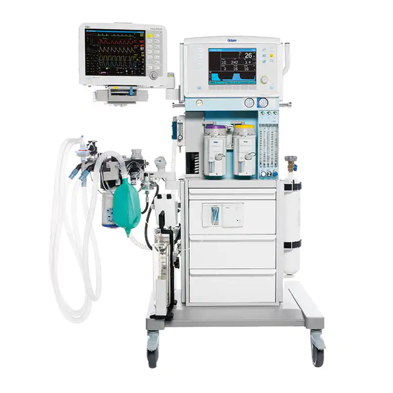
Electromagnetic compatibility complies with IEC 60 601-1-2 6.13 Dimensions and Weight Dimensions (W x H x D) 960 mm x 1280 mm x 620 mm (with 1 absorber) Weight 82 kg (without gas cylinders) Page 26 5330.200 Fabius 06/98 General... - Page 30 S-ORC ventilator anesthetic vaporizer "Vapor 19.n" max. 134 C trolley Fig. 2: Fabius equipped with a circle absorption system "Circle System 9 Fabius" Page 28 5330.200 Fabius 02/99 Function Description...
- Page 31 Fabius provides connections for the following medical gas cylinders: − O cylinder − N O cylinder Fabius can be retrofitted with the following assemblies/functions: − drawer assembly − rechargeable batteries for uninterruptible power supply (UPS) − additional gas (AIR) − cylinder set mount Page 29 5330.200 Fabius...
-
Page 32: Fabius Function Diagrams
PEEP control valve APL valve SPONT/ IPPV electronic PEEP valve piston pump outlet Fig. 3: Function diagram of Fabius with compact breathing system "Cosy" Page 30 5330.200 Fabius 02/99 Function Description... - Page 33 1st absorber PEEP valve flow APL valve electronic SPONT/ PEEP valve IPPV breathing piston pump outlet Fig. 4: Function diagram of Fabius with circle absorption system "Circle System 9 Fabius" Page 31 5330.200 Fabius 02/99 Function Description...
-
Page 34: Optional Uninterruptible Power Supply (Ups)
Connection is made on the rear panel of the control box. control box 5 V regulator ventilator monitor uninteruptible power supply (UPS) Fig. 5: Block diagram of Fabius’ voltage supply Page 32 5330.200 Fabius 02/99 Function Description... - Page 35 GBF5330200T01.fm 19.01.00 For internal use only. Copyright reserved. fresh gas flowmeter block whistle gas box flowmeters injector O 2 flush reservoir suction ejector anesthetic vaporizer filter pressure regulator filter pressure regulator S-ORC pressure N 2 O gauges filter N 2 O non-return valves filter...
- Page 36 GBF5330200T01.fm 19.01.00 For internal use only. Copyright reserved. fresh gas flowmeter block whistle gas box injector O 2 flush reservoir suction ejector 3 bar anesthetic vaporizer filter 1.5 bar 2 bar filter pressure regulators S-ORC pressure N 2 O gauges N 2 O non-return valves...
-
Page 37: Function Description Of The Gas Box
N 2 O gauges filter N 2 O non-return valves Fig. 8: Function diagram of the gas box (3-gas version), part 1 Page 35 5330.200 Fabius 02/99 Function Description... - Page 38 This avoids an increase in the anesthetic gas concentration. fresh-gas ejector fresh gas O 2 flush anesthetic vaporizer Fig. 9: Function diagram of the gas box (3-gas version), part 2 Page 36 5330.200 Fabius 02/99 Function Description...
-
Page 39: S-Orc (Sensitive Oxygen Ratio Controller)
(O 2 ) from the gas box (AIR) safety valve (<1 bar) S-ORC from the gas box (N 2 O) Fig. 10: S-ORC function diagram, part 1 Page 37 5330.200 Fabius 02/99 Function Description... - Page 40 9 L/min. N 2 O flowmeters restrictors control diaphragms N 2 O check valve operating-point adjusting screw N 2 O flow control valves Fig. 11: S-ORC function diagram, part 2 Page 38 5330.200 Fabius 02/99 Function Description...
-
Page 41: Compact Breathing System "Cosy" / Circle Absorption System "Circle System 9 Fabius
Compact Breathing System "Cosy" / Circle Absorption System "Circle System 9 Fabius" Fabius is either equipped with a compact breathing system "Cosy" or with a circle absorption system "Circle System 9 Fabius". They have the same function. Compact Breathing System "Cosy"... - Page 42 Flow sensor (APL valve) Fresh-gas port Fresh-gas decoupling valve Ventilator port Breathing bag mount Anesthetic gas scavenging port Inspiratory port Absorber Inspiratory valve Pressure sensor connector Breathing bag terminal Sample-gas return line port (optional) Page 40 5330.200 Fabius 02/99 Function Description...
- Page 43 APL valve 9 limits the ventilation pressure. Any excess amount of the gas mixture flows through the APL valve 9 and the non-return valve 10 to the anesthetic gas scavenging system. fresh gas Fig. 13: Manual ventilation (inspiration) Page 41 5330.200 Fabius 02/99 Function Description...
- Page 44 4, the flow sensor 5, the PEEP control valve 6, the expiratory valve 7, and through the absorber 8 into the breathing bag 2. At the same time, new fresh gas flows into the breathing bag 2. fresh gas Fig. 14: Manual ventilation (expiration) Page 42 5330.200 Fabius 02/99 Function Description...
- Page 45 The gas mixture flows through the fresh-gas decoupling valve 3, the inspiratory valve 4, the sensor 5, the inspiratory hose 6, and through the Y-piece into the lung 7. The pressure sensor 8 measures the airway pressure. fresh gas SPONT/ IPPV Fig. 15: Spontaneous breathing (inspiration) Page 43 5330.200 Fabius 02/99 Function Description...
- Page 46 Fig. 16: Spontaneous breathing (expiration) The CO is scrubbed from the expiratory gas by the soda lime contained in the absorber 8. The fresh gas replaces the anesthetic and oxygen taken up by the patient. Page 44 5330.200 Fabius 02/99 Function Description...
- Page 47 The safety valve of the patient system makes sure that no pressures greater than 80 hPa (mbar) build up in the system. The pressure limit (Pmax) can be adjusted on the control box. Page 45 5330.200 Fabius 02/99 Function Description...
- Page 48 Any excess fresh gas flows through the open APL valve 9, and through the non-return valve 10 into the anesthetic gas scavenging system. fresh gas SPONT/ IPPV Fig. 17: Intermittent positive pressure ventilation (inspiration) Page 46 5330.200 Fabius 02/99 Function Description...
- Page 49 Any excess fresh-gas flows through the APL valve 9, and through the non-return valve 10 into the anesthetic gas scavenging system. fresh gas SPONT/ IPPV Fig. 18: Intermittent positive pressure ventilation (expiration) Page 47 5330.200 Fabius 02/99 Function Description...
- Page 50 Spent soda lime changes its color. The soda lime must be replaced when two thirds of the soda lime in a canister are discolored. Page 48 5330.200 Fabius 02/99 Function Description...
- Page 51 Circle Absorption System "Circle System 9 Fabius" The circle absorption system "Circle System 9 Fabius" allows three modes of patient ventilation: manual ventilation, spontaneous breathing, intermittent positive pressure ventilation (IPPV). The APL valve (adjustable pressure limiting valve) has a selector which can be used to toggle between "MAN"...
- Page 52 Fig. 19: Circle absorption system "Circle System 9 Fabius" Inspiratory valve Non-return valve Pressure-measuring port (Paw) APL valve Fresh-gas decoupling valve MAN/SPONT-IPPV selector Fresh-gas port Flow sensor First absorber Expiratory valve Second absorber (optional) PEEP valve Clamping screw Ventilator port...
- Page 53 APL valve 8. The expiratory valve 9 remains closed. Any excess amount of the gas mixture flows through the APL valve 8, and the non-return valve 10 into the anesthetic gas scavenging system 11. Fig. 20: Manual ventilation (inspiration) Page 51 5330.200 Fabius 02/99 Function Description...
- Page 54 3 and the flow sensor 4 into the breathing bag 2. At the same time, fresh gas from the fresh-gas port 5 flows through the absorber(s) into the breathing bag 2. Fig. 21: Manual ventilation (expiration) Page 52 5330.200 Fabius 02/99 Function Description...
- Page 55 Fig. 22: Spontaneous Breathing (inspiration phase) The CO is scrubbed from the expiratory gas by the soda lime contained in the absorber(s) 3. The fresh gas replaces the anesthetic and the oxygen taken up by the patient. Page 53 5330.200 Fabius 02/99 Function Description...
- Page 56 8 into the breathing bag 6. When the breathing bag 6 is full, any excess gas mixture flows through the non-return valve 9 into the anesthetic gas scavenging system 10. Fig. 23: Spontaneous breathing (expiration) Page 54 5330.200 Fabius 02/99 Function Description...
- Page 57 If the APL valve selector is not set to the "IPPV/SPONT" position, the pressure in the breathing system will increase. The safety valve of the patient system limits the pressure to 80 hPa (mbar). The desired pressure limit (Pmax) can be adjusted on the control box. Page 55 5330.200 Fabius 02/99 Function Description...
- Page 58 Fig. 24: Intermittent positive pressure ventilation (inspiration) If the inspiratory pressure exceeds the set pressure limit (Pmax), the PEEP valve opens. Any excess gas flows through the PEEP valve, and the flow sensor into the circle absorption system. Page 56 5330.200 Fabius 02/99 Function Description...
- Page 59 PEEP valve. The diaphragm plate of the PEEP valve pushes the mica disc of the expiratory valve which closes the crater. If the pressure of the expiratory gas exceeds the set PEEP value, the expiratory valve 2 opens. Page 57 5330.200 Fabius 02/99 Function Description...
- Page 60 Spent soda lime changes its color. The soda lime must be replaced when two thirds of the soda lime in a canister are discolored. Page 58 5330.200 Fabius 02/99 Function Description...
-
Page 61: Ventilation Unit
Ventilator The ventilator is mounted into the swivel-out compartment of Fabius. The cover of the ventilator has a connection for the respiratory hose of the circle absorption system or compact breathing system, respectively. The ventilator is powered electrically. Its control system and keypad are located in/on the control box. - Page 62 The rolling seal is attached to the piston. The bag-type rolling seal encloses the inspiratory volume. patient system cylinder bag-type rolling seal rolling seal piston recirculating ball screw motor incremental encoder Fig. 26: Sectional view of the ventilator Page 60 5330.200 Fabius 02/99 Function Description...
-
Page 63: Pneumatics
The pneumatics comprises the following subassemblies: − electronic PEEP valve − Pneumatic Control PCB − piston pump − pressure sensor electronic Pneumatic PEEP valve Control PCB piston pump pressure sensor Fig. 27: Top view of the pneumatics Page 61 5330.200 Fabius 02/99 Function Description... - Page 64 PEEP valve. The combination of filter and reservoir V2 dampen the noise. pneumatics electronic PEEP valve reservoir V1 piston ventilator pump to the PEEP valve/ expiratory valve –200 hPa (mbar) filter reservoir V2 Fig. 28: Function diagram of the pneumatic control of the ventilator Page 62 5330.200 Fabius 02/99 Function Description...
-
Page 65: Function Description Of The Electronic Peep Valve
During inspiration, the electronic PEEP valve generates a control pressure which corresponds to the set pressure limit (Pmax). electronic PEEP valve flow from piston pump to the PEEP control valve to atmosphere coil diaphragm Fig. 29: Function diagram of the electronic PEEP valve Page 63 5330.200 Fabius 02/99 Function Description... -
Page 66: Patient System
Patient System The patient system provides the connection between Fabius and the patient. auxiliary-air valve patient connection safety valve patient system Fig. 30: Top view of the patient system Page 64 5330.200 Fabius 02/99 Function Description... -
Page 67: Safety Valve Of The Patient System
This safety valve is permanently set to a working pressure of 60 hPa (mbar) to 80 hPa (mbar). screw spring valve disc washer Fig. 31: Sectional view of the safety valve Page 65 5330.200 Fabius 02/99 Function Description... -
Page 68: Auxiliary Air Valve Of The Patient System
Auxiliary Air Valve of the Patient System The auxiliary air valve allows the patient to spontaneously breathe ambient air should the medical gas supply and/or Fabius fail. The opening pressure of the auxiliary air valve is 0 to –5 hPa (mbar). - Page 69 GBF5330200T01.fm 19.01.00 For internal use only. Copyright reserved. Buzzer Control PCB Power PCB Power Supply PCB 2-min Flow channel Flow sensor silence Peripherals P(t) channel Transformer 110VAC/ channel 220VAC sensor EPROM EPROM Microcontroller EEPROM Microcontroller Voltage supply Relay ±12V External battery Voltage Quadrature transformer...
-
Page 70: Control Pcb
Power Supply PCB Mains filter Mains transformer Front panel (front frame and membrane keypad) Control knob Power PCB Graphics display and backlighting lamp Control PCB Rechargeable battery Differential pressure sensor (flow) Airway pressure sensor (Paw) Page 68 5330.200 Fabius 02/99 Function Description... - Page 71 Fig. 35: Rear View of the Control Box Mains supply receptacle with mains fuses ON/OFF switch Equipotential bonding pin Flow sensor port sensor port Pressure sensor port (Paw) Motor connector Pneumatics connector Power cord clamp Page 69 5330.200 Fabius 02/99 Function Description...
- Page 72 The power supply unit consists of the Power Supply PCB, the mains supply receptacle, the ON/OFF switch, the fuses, the mains filter, and the mains transformer. The power supply unit powers Fabius with the following voltages: − +24 VDC − +5 VDC 10.1.1...
- Page 73 4 AT switch 2.5 A 2 step-down controller bridge-connected rectifier 3.15 A 40 VAC mains transformer mains filter mains connection 2 x1 AT Fig. 36: Block diagram of the control box power supply unit Page 71 5330.200 Fabius 02/99 Function Description...
- Page 74 − buzzer and buzzer control − contrast control − membrane keypad scanning − control knob scanning − motor current monitoring − membrane pressure − charging voltage monitoring − display control − ±12 V generation Page 72 5330.200 Fabius 02/99 Function Description...
- Page 75 GBF5330200T01.fm 19.01.00 For internal use only. Copyright reserved. Flow CONTRAST EEPROM Differential 512kx8 Voltage pressure sensor PSEN GNDA transformer sensor EPROM (±12 V) V– 32kx8 512kx8 (optional) VCONTRAST (approx. –7 V) Address 12MHz Data Latch Data Data PUMP ON (on/off) U BATT (charging voltage) PEEP ON BATT_NETZ...
- Page 76 IC 7665 generates a RESET signal. This RESET signal resets the microcontroller. The IC makes sure that the microcontroller only initializes when the operating voltage has reached an adequate level. Page 74 5330.200 Fabius 02/99 Function Description...
- Page 77 In the event of a power failure, the 9 V rechargeable battery supplies the operating voltage for the buzzer. The 24 V operating voltage supplies a charging circuit which charges the rechargeable battery during normal operation. Page 75 5330.200 Fabius 02/99 Function Description...
- Page 78 − voltage transformer for the backlighting lamp − PEEP valve control − light barrier evaluation of the motor (limit switch) − system temperature monitoring and fan control − quadrature encoder − safety relay Page 76 5330.200 Fabius 02/99 Function Description...
- Page 79 GBF5330200T01.fm 19.01.00 For internal use only. Copyright reserved. To drive and pneumatic unit Safety relay GNDD Motor FET power transistors Quadrature current encoder PUMP PEEP Level Level Level Level transf. transf. transf. transf. MOTI (analog) PUMP_ON (on/off) TEMP PEEP_AN (PWM 10 kHZ, 0...100%) GNDD P MEMBRAN (analog) NOT_AUS (on/off)
- Page 80 The power field-effect transistor BUZ20 and the operational amplifier LM324 control the PEEP valve. 10.5.8 Light Barrier Evaluation of the Motor The IC 74HC14 evaluates the final position and the movement of the motor (END-SCH, PHASE0, and PHASE1). Page 78 5330.200 Fabius 02/99 Function Description...
- Page 81 NOT_AUS (emergency off) signal. As a result, the motor, the electronic PEEP valve, the piston pump, and the fan can no longer be activated. 10.5.12 Fan Control If the system temperature inside the control box increases (to approx. 60 °C), the microcontroller activates the fan. Page 79 5330.200 Fabius 02/99 Function Description...
-
Page 82: Graphics Display
RESET inverter LCD controller x driver x driver x driver LC display y driver (240 x 64 pixels) + 5 V backlighting lamp 300 VAC Fig. 39: Block diagram of the graphics display Page 80 5330.200 Fabius 02/99 Function Description... -
Page 83: Front Panel
Man/Spont key. 10.7.3 IPPV Key Fabius can be set to intermittent positive pressure ventilation by pressing the IPPV key. 10.7.4 Pmax Key The inspiratory pressure limit can be set in a range of 10 hPa (mbar) to 70 hPa (mbar) by pressing the Pmax key. -
Page 84: Interface
After pressing the standby key, the control box switches over to standby mode. 10.7.13 Menu Key After pressing the menu key, it is possible to configure Fabius. 10.7.14 Screen Page Key After pressing the screen page key, it possible to select different screen pages. -
Page 85: Fio2 Measurement
Due to the two gold cathodes used in the O sensor cell, two different measuring voltages are generated. These measuring voltages are compared with each other. If the O sensor fails, the control box will indicate an error on the graphics display. Page 83 5330.200 Fabius 02/99 Function Description... -
Page 86: Flow Measurement
1 ∆ P results from the differential pressure (back-pressure from measuring lines 1 and 2) measuring line 2 Fig. 41: Flow measurement principle Page 84 5330.200 Fabius 02/99 Function Description... -
Page 87: Anesthetic Vaporizer "Vapor 19.N
Anesthetic Vaporizer "Vapor 19.n" Refer to separate technical documentation of the anesthetic vaporizer "Vapor 19.n". Page 85 5330.200 Fabius 02/99 Function Description... -
Page 88: Test List
Fabius 02.99 Serial no.: ————————— Installation site: ————————— Fabius S-ORC max. 134¡C This test list does not replace the inspections and servicing to be carried out by Dräger Medical AG & Co. KGaA Page 86 5330.200 Fabius 02.99 Test list... - Page 89 10 to 120 L/min Test pressure reducer Hoses, various T-piece Test thorax This test list does not replace the inspections and servicing to be carried out by Dräger Medical AG & Co. KGaA Page 87 5330.200 Fabius 02.99 Test list...
-
Page 90: General Condition
• Check the general condition of the “Ventilator”. Either the “Cosy” compact breathing system or the “Circle system 9/Fabius” circle absorption system may be fitted on the Fabius. Select the appropriate test for your component. This test list does not replace the inspections and servicing to be carried out by Dräger Medical AG & Co. KGaA Page 88 5330.200 Fabius... - Page 91 − Patient airway pressure measuring tube − Y-piece − Mask − Absorber 1.3.2 “Circle system 9/Fabius” circle absorption system • Check the general condition of the existing accessories: − Circle system carrier − Inspiratory valve − Expiratory valve − PEEP valve −...
-
Page 92: Flowmeter Block
• Check the general condition of the drawers. CS connecting tubes/connectors • Check the general condition of the central supply system connecting tubes and the compressed gas connectors of the Fabius. 1.10 Compressed gas cylinders and pressure gauges • Check the general condition of the compressed gas cylinders and the associated pressure gauges. -
Page 93: Tests To Vde 0751, Part
≤ value of the unit by max. 50%, but are 750 µA. This test list does not replace the inspections and servicing to be carried out by Dräger Medical AG & Co. KGaA Page 91 5330.200 Fabius 02.99 Test list... -
Page 94: Test Fabius Functions
• Connect the Fabius to the anaesthetic gas scavenging system. • Plug the mains plug of the Fabius into the mains socket. • Switch on the Fabius. • Check that all LEDs on the control box light up briefly, that the audible alarm sounds and that the Fabius runs through its self-test and then switches to STANDBY mode. -
Page 95: Test Gas Type (Compressed Gas Cylinders)
-Flush key of the Fabius pressed down until you can hear that no more gas is flowing. The compressed gas remaining in the Fabius escapes. The Fabius is depres- surised. • Check that the pressure gauges indicate 0 bar after approx. 2 seconds. -
Page 96: Testing Gas Type (Central Supply System)
-Flush key on the Fabius pressed down until you can hear that no more gas is flowing. • Check that the remaining compressed gas in the Fabius escapes. The Fabius is depressurised. • Close all flow control valves of the flowmeter block. -
Page 97: Test O2 Shortage Warning
(central supply system/com- pressed gas cylinder) to the Fabius. Test O shortage warning time • Leave the Fabius connected to the O compressed gas supply for 15 seconds. (Note: Vessel filling time of the volume). • Disconnect the O compressed gas supply from the Fabius. -
Page 98: Test O2 Flush
Test O flush • Unscrew the fresh gas hose from the fresh gas outlet of the Fabius. • Connect the fresh gas outlet to a flowmeter (measuring range up to 120 L/min). • Hold the O -Flush key pressed down. -
Page 99: Test S-Orc
• Check that the N O flowmeter is indicating a N O flow between 6.0 L/min and 10.0 L/min. • Refit the “Vapor” anaesthetic vaporizer on the Fabius. • Close the O flow control valve. • Close the N O flow control valve. -
Page 100: Check For Leaks
• Hold the O -Flush key of the Fabius pressed down until you can hear that no more gas is flowing. • Check that the remaining compressed gas in the Fabius escapes. The Fabius is depressurised. • Close all flow control valves. - Page 101 • Open the N O compressed gas cylinder valve. • Switch on the Fabius by the power switch. • On the control box press the “MAN/SPONT” key. • Detach the manual breathing bag from its connection port.
- Page 102 • Open the N O compressed gas cylinder valve. • Switch on the Fabius by the power switch. • On the control box press the “MAN/SPONT” key. • Detach the manual breathing bag from its connection port.
-
Page 103: Test Low Pressure
• Check that the float of the O flowmeter is indicating a flow of < 0.1 L/min. • Refit the “Vapor” anaesthetic vaporizer on the Fabius. • Close the O flow control valve. - Page 104 < 0.1 L/min. • Close the O flow control valve. This test list does not replace the inspections and servicing to be carried out by Dräger Medical AG & Co. KGaA Page 102 5330.200 Fabius 02.99 Test list...
-
Page 105: Test Ventilator
3.12 Test ventilator • Plug the mains plug of the Fabius into the mains socket. • Switch on the Fabius by the power switch. 3.12.1 Test machine breathing • Connect a test thorax or a breathing bag. • Set AIR to approx. 3 L/min. - Page 106 Fabius and its components/accessories according to approved hospital procedures before servicing or shipping for repair. Risk of electric shock! Unplug the power cord before opening Fabius, the ventilator, or the control box for servicing. Risk of malfunction! Spare items from another manufacturer can affect the device’s function.
-
Page 107: Maintenance Intervals
Maintenance Intervals Observe the following maintenance intervals: Regular Safety Checks Item Procedure/Intervals Circle absorption system Check at regular intervals. "Circle System 9/Fabius" Anesthetic vaporizer "Vapor 19.n" Check at regular intervals. Sensors (O sensor, flow sensor) Check at regular intervals. Fabius Check at regular intervals. -
Page 108: Maintenance At 6-Month Intervals
Maintenance at 6-Month Intervals Item Procedure/Intervals Circle absorption system To be maintained by trained service personnel at "Circle System 9/Fabius" six-month intervals. Anesthetic vaporizer "Vapor 19.n" To be maintained by trained service personnel at six-month intervals. Sensors (O sensor, flow sensor) To be maintained by trained service personnel at six-month intervals. -
Page 109: Maintenance At 3-Year Intervals
Risk of injury! Any battery may rupture or explode if put in a fire or otherwise exposed to excessive heat. Do not expose batteries to excessive heat. Dispose of batteries according to local waste disposal regulations. Page 107 5330.200 Fabius 06/98 Replacing Non-Repairable Items... -
Page 110: Maintenance At 6-Year Intervals
Procedure/Intervals Pressure regulators To be submitted to a general overhaul by trained service personnel at 6-year intervals. 2.6.1 Disposing of Pressure Regulators Dispose of pressure regulators according to local waste disposal regulations. Page 108 5330.200 Fabius 06/98 Replacing Non-Repairable Items... -
Page 111: Sensor
Removing/Replacing the O Sensor • Switch off Fabius using the ON/OFF switch (on the rear panel of the control box). • Unplug the O sensor connector from the O sensor input port 1 on the control box. - Page 112 • Unscrew the O sensor assembly 1 from the inspiratory valve. inspiratory valve Fig. 2: Circle Absorption System "Circle System 9/Fabius" (removing the O sensor assembly) • Unscrew the O sensor cap from the O sensor housing. O 2 sensor cap...
-
Page 113: Disposing Of Spent O
• Plug the O sensor connector into the O sensor input port on the control box. • Switch on Fabius using the ON/OFF switch. • Calibrate the O sensor in the STANDBY mode. Disposing of Spent O Sensors Risk of injury! O sensors contain harmful chemicals. -
Page 114: Flow Sensor
Replace the flow sensor with a new one when calibration is no longer possible. Removing/Replacing the Flow Sensor • Switch off Fabius using the ON/OFF switch (on the rear panel of the control box). ON/OFF switch 1 AT 1 AT... -
Page 115: Disposing Of The Spent Flow Sensors
• To secure the flow sensor in place, turn the union nut clockwise (downward) as far as it will go. Flow sensor Fig. 6: Circle Absorption System "Circle System 9/Fabius" (installing the flow sensor) • Connect the flow measuring hoses to the flow sensor. • Switch on Fabius using the ON/OFF switch. -
Page 116: Rechargeable Battery In The Control Box
Use a static-dissipative mat and a wrist strap when handling electrostatic sensitive devices. • Switch off Fabius using the ON/OFF switch (on the rear panel of the control box). • Disconnect the power plug of Fabius from the mains socket-outlet. - Page 117 Fig. 7: Front View of the Control Box (removing the top cover) • Cut off the cable tie 3 which holds the battery in place. Fig. 8: Top View of the Control Box (top cover removed), Removing the Cable Tie Page 115 5330.200 Fabius 06/98 Replacing Non-Repairable Items...
-
Page 118: Disposing Of The Rechargeable Battery In The Control Box
• Mount the top cover onto the control box. • Connect the power plug of Fabius to the mains socket-outlet. • Switch on Fabius and allow the new rechargeable battery to recharge for at least one hour. Disposing of the Rechargeable Battery in the Control Box Dispose of spent rechargeable batteries according to local waste disposal regulations. -
Page 119: Rechargeable Batteries Of The Uninterruptible Power Supply (Ups)
Risk of injury! Any battery may rupture or explode if put in a fire or otherwise exposed to excessive heat. Do not expose batteries to excessive heat. Page 117 5330.200 Fabius 06/98 Replacing Non-Repairable Items... -
Page 120: Removing/Replacing The Rechargeable Batteries Of The Ups
Use a static-dissipative mat and a wrist strap when handling electrostatic sensitive devices. • Switch off Fabius by using the ON/OFF switch (on the rear panel of the control box). • Disconnect the power plug of Fabius from the mains socket-outlet. -
Page 121: Disposing Of Rechargeable Batteries Of The Ups
• Replace the rechargeable batteries with new ones. • Tie the connecting cables of the rechargeable batteries together using a new cable tie. • Install the new rechargeable batteries into Fabius (connect the grounding cable to the nut 2, see Figure above). -
Page 122: Pressure Regulators
6-year intervals. Removing/Replacing the Pressure Regulators • Switch off Fabius using the ON/OFF switch (on the rear panel of the control box). • Disconnect the power plug from the mains socket-outlet. • Disconnect the gas connectors from the terminal units/gas cylinders. - Page 123 AIR pressure regulator pressure regulator O pressure regulator (optional) Fig. 13: Side View of the Plug-In Unit (location of the hoses) Page 121 5330.200 Fabius 06/98 Replacing Non-Repairable Items...
- Page 124 Dispose of the pressure regulators according to local waste disposal regulations. • Secure the new pressure regulator using the lock nut. pressure regulator lock nut Fig. 14: Pressure Regulator (disconnecting the hoses) Page 122 5330.200 Fabius 06/98 Replacing Non-Repairable Items...
- Page 125 O pressure regulator. • Using a test pressure regulator, deliver a flow of 3 L/min to the N O input port of Fabius. • Using the adjusting ring 1, set the N O pressure regulator to 2.0 bar ±0.2 bar (the pressure regulator can be opened by turning the adjusting ring clockwise).
-
Page 126: Disposing Of Pressure Regulators
• Remove the T-piece and the separate pressure gauge. • Check that the hose system is free of leaks (for example with a leak detector spray). • Reassemble Fabius using the reverse method of that used for disassembly. Disposing of Pressure Regulators Dispose of the pressure regulators according to local waste disposal regulations. - Page 127 GBK5330200D01.fm 19.01.00 For internal use only. Copyright reserved. M31602 450 lg O 2 pressure 840274 M30937 regulator 400 lg M31991 100 lg N 2 O pressure M30946 regulator M31602 input port 160 lg (cylinder supply) M28817 M31602 M31602 M30937 85 lg M31602 M31602 M31602...
-
Page 128: Fault − Cause − Remedy
IPPV mode. BATTERY LOW The battery voltage of the Recharge the batteries of the UPS uninterruptible power supply by running Fabius from the mains (UPS) is too low. power supply for four hours. BATTERY POWERED Fabius is not connected to... - Page 129 The flow sensor has been Calibrate the flow sensor. replaced but not calibrated. The flow sensor hose is Replace the flow sensor hose and faulty. calibrate the flow sensor. − − Page 127 5330.200 Fabius 06/98 Fault Cause Remedy...
- Page 130 Fault Cause Remedy MEMORY ERROR Internal data loss. Switch Fabius off and on. Inform DrägerService, if necessary. MV HIGH The upper alarm limit for the Calibrate the flow sensor (see minute volume has been Instructions for Use). exceeded. The flow sensor has not Calibrate the flow sensor.
- Page 131 VENTILATOR INOP Internal machine fault. Switch Fabius off and on. IPPV mode is not Inform DrägerService. operational. VOL ALARM OFF The lower alarm limit for MV Set the appropriate lower alarm limit is off in the IPPV mode.
-
Page 132: Changes
This service manual reflects the state of technology which applied in June 1998. Type of Change Date Spare Parts list new 11.98 Function Description with „Cosy“ new 02.99 Spare Parts list „Cosy“ new 03.99 Test list new 11.99 Page 130 5330.200 Fabius 06/99 Changes... -
Page 133: Appendix
Peak Pressure PEEP Positive End-Expiratory Pressure Pmax Maximum Pressure (Limit) Pmean Mean Pressure S-ORC Sensitive Oxygen Ratio Controller Inspiratory to Expiratory Time Ratio Inspiratory Pause Time to Inspiratory Time Ratio Expired Ventilation Tidal Volume Page 131 5330.200 Fabius 06/98 Appendix... -
Page 134: Spare Parts List
Spare Parts List Fabius Compact breathing system Cosy Page 132 5330.200 Fabius 06/98 Appendix... - Page 135 Dräger DrägerService Medizintechnik DrägerService Medical Division Ausgabe/Edition Ersatzartikelliste 5330.200 24.10.01 Spare parts list FABIUS Seite/Page 1 von 59 FABIUS Druckdatum: 26.10.2001 Änderungen vorbehalten Printed Subject to change without notice...
- Page 136 Seite/Page 2 von 59 FABIUS Diese Ersatzartikelliste gilt für Sachnummer: This spare parts list is valid for part no.: Sach-Nr. Benennung Part No. Description FABIUS CE 2GAS 2601000 FABIUS CE 2-GASES 2603000 FABIUS CE-3-GAS FABIUS CE-3-GASES 2603500 FABIUS-CE-3GAS-US-STANDARD FABIUS CE-3GAS US-STANDARD Druckdatum: 26.10.2001...
- Page 137 Seite/Page 3 von 59 FABIUS Inhaltsverzeichnis der Bilder Summary of pictures Bild Bezeichnung Sach-Nr. E-Liste Picture Description Part No . Spare parts list FABIUS CE 3-GAS 2603000 FABIUS CE 3-GASES FAHRGESTELL 2603200 TROLLEY FAHRGESTELL 2603200 TROLLEY GASBOX 2603010 GASBOX GASBOX...
- Page 138 Dräger DrägerService Medizintechnik DrägerService Medical Division Ausgabe/Edition Ersatzartikelliste 5330.200 24.10.01 Spare parts list FABIUS Seite/Page 4 von 59 FABIUS Bild Bezeichnung Sach-Nr. E-Liste Picture Description Part No . Spare parts list FLOWMETER (2-GAS) 2600332 FLOWMETER (2-GASES) FLOWMETER (2-GAS) 2600332 FLOWMETER (2-GASES)
- Page 139 Dräger DrägerService Medizintechnik DrägerService Medical Division Ausgabe/Edition Ersatzartikelliste 5330.200 24.10.01 Spare parts list FABIUS Seite/Page 5 von 59 FABIUS FABIUS CE 3-GAS Bild/Picture 1 FABIUS CE 3-GASES Datei/File: 5330200.001 Druckdatum: 26.10.2001 Änderungen vorbehalten Printed Subject to change without notice...
- Page 140 FABIUS CE-3-GAS 2603000 FABIUS CE-3-GASES FABIUS-CE-3GAS-US-STANDARD 2603500 Pos. Nr. 1, 2a, 3-19, 20a, 21a, 22-24 FABIUS CE-3GAS US-STANDARD item no. 1, 2a, 3-19, 20a, 21a, 22-24 FABIUS CE 2GAS 2601000 Pos. Nr. 1, 2b, 3-19, 20b, 21b, 22-24 FABIUS CE 2-GASES item no.
- Page 141 Dräger DrägerService Medizintechnik DrägerService Medical Division Ausgabe/Edition Ersatzartikelliste 5330.200 24.10.01 Spare parts list FABIUS Seite/Page 7 von 59 FABIUS Position Benennung Sach-Nr. Bestell-Nr. Packung Item No. Description Part No. Order-Code Quantity WASSERFALLE 8404985 ohne Abbildung WATER SEPARATOR without illustration EINFUELLTRICHTER...
- Page 142 Dräger DrägerService Medizintechnik DrägerService Medical Division Ausgabe/Edition Ersatzartikelliste 5330.200 24.10.01 Spare parts list FABIUS Seite/Page 8 von 59 FABIUS Position Benennung Sach-Nr. Bestell-Nr. Packung Item No. Description Part No. Order-Code Quantity FRISCHGASSCHLAUCH ISO 2600170 COMMON GAS HOSE ISO FRISCHGASSCHLAUCH 0,7M...
- Page 143 Dräger DrägerService Medizintechnik DrägerService Medical Division Ausgabe/Edition Ersatzartikelliste 5330.200 24.10.01 Spare parts list FABIUS Seite/Page 9 von 59 FABIUS FAHRGESTELL Bild/Picture 2 TROLLEY Datei/File: 5330200.002 Druckdatum: 26.10.2001 Änderungen vorbehalten Printed Subject to change without notice...
- Page 144 Dräger DrägerService Medizintechnik DrägerService Medical Division Ausgabe/Edition Ersatzartikelliste 5330.200 24.10.01 Spare parts list FABIUS Seite/Page 10 von 59 FABIUS FAHRGESTELL Bild/Picture 3 TROLLEY Datei/File: 5330200.003 Druckdatum: 26.10.2001 Änderungen vorbehalten Printed Subject to change without notice...
- Page 145 Dräger DrägerService Medizintechnik DrägerService Medical Division Ausgabe/Edition Ersatzartikelliste 5330.200 24.10.01 Spare parts list FABIUS Seite/Page 11 von 59 FABIUS Position Benennung Sach-Nr. Bestell-Nr. Packung Item No. Description Part No. Order-Code Quantity 1-24 FAHRGESTELL,KOMPL. 2603200 TROLLEY-CE PROFIL M29336 PROFILE KNEBELSCHRAUBE 2600230...
- Page 146 Dräger DrägerService Medizintechnik DrägerService Medical Division Ausgabe/Edition Ersatzartikelliste 5330.200 24.10.01 Spare parts list FABIUS Seite/Page 12 von 59 FABIUS Position Benennung Sach-Nr. Bestell-Nr. Packung Item No. Description Part No. Order-Code Quantity WINKEL 2600252 SQUARE BAR TELESKOPSCHIENE 2M18364 TELESCOPE RAIL DISTANZSTUECK...
- Page 147 Dräger DrägerService Medizintechnik DrägerService Medical Division Ausgabe/Edition Ersatzartikelliste 5330.200 24.10.01 Spare parts list FABIUS Seite/Page 13 von 59 FABIUS GASBOX Bild/Picture 4 GASBOX Datei/File: 5330200.004 Druckdatum: 26.10.2001 Änderungen vorbehalten Printed Subject to change without notice...
- Page 148 Dräger DrägerService Medizintechnik DrägerService Medical Division Ausgabe/Edition Ersatzartikelliste 5330.200 24.10.01 Spare parts list FABIUS Seite/Page 14 von 59 FABIUS GASBOX Bild/Picture 5 GASBOX Datei/File: 5330200.005 Druckdatum: 26.10.2001 Änderungen vorbehalten Printed Subject to change without notice...
- Page 149 Dräger DrägerService Medizintechnik DrägerService Medical Division Ausgabe/Edition Ersatzartikelliste 5330.200 24.10.01 Spare parts list FABIUS Seite/Page 15 von 59 FABIUS Position Benennung Sach-Nr. Bestell-Nr. Packung Item No. Description Part No. Order-Code Quantity 1-14 GASBOX 3-GAS (S-ORC) 2603010 3-GAS S-ORC 1-14 GASBOX 3-GAS US...
- Page 150 Dräger DrägerService Medizintechnik DrägerService Medical Division Ausgabe/Edition Ersatzartikelliste 5330.200 24.10.01 Spare parts list FABIUS Seite/Page 16 von 59 FABIUS FLOWMETER (3-GAS) Bild/Picture 6 FLOWMETER (3-GASES) Datei/File: 5330200.006 Druckdatum: 26.10.2001 Änderungen vorbehalten Printed Subject to change without notice...
- Page 151 Dräger DrägerService Medizintechnik DrägerService Medical Division Ausgabe/Edition Ersatzartikelliste 5330.200 24.10.01 Spare parts list FABIUS Seite/Page 17 von 59 FABIUS FLOWMETER (3-GAS) Bild/Picture 7 FLOWMETER (3-GASES) Datei/File: 5330200.007 Druckdatum: 26.10.2001 Änderungen vorbehalten Printed Subject to change without notice...
- Page 152 Dräger DrägerService Medizintechnik DrägerService Medical Division Ausgabe/Edition Ersatzartikelliste 5330.200 24.10.01 Spare parts list FABIUS Seite/Page 18 von 59 FABIUS Position Benennung Sach-Nr. Bestell-Nr. Packung Item No. Description Part No. Order-Code Quantity 1-22 FLOWMETER 3GAS EURO-O2,N2O,AIR 2603012 FLOWMETER 3GAS EURO-O2,N2O,AIR KAPPE,WEISS...
- Page 153 Dräger DrägerService Medizintechnik DrägerService Medical Division Ausgabe/Edition Ersatzartikelliste 5330.200 24.10.01 Spare parts list FABIUS Seite/Page 19 von 59 FABIUS Position Benennung Sach-Nr. Bestell-Nr. Packung Item No. Description Part No. Order-Code Quantity DRUCKRING 4 MM,WEISS M31602 THRUST COLLAR 4, WHITE MANOMETER...
- Page 154 Dräger DrägerService Medizintechnik DrägerService Medical Division Ausgabe/Edition Ersatzartikelliste 5330.200 24.10.01 Spare parts list FABIUS Seite/Page 20 von 59 FABIUS ZWEIGASEINGANG Bild/Picture 8 TWO GAS INLET FIXING Datei/File: 5330200.008 Druckdatum: 26.10.2001 Änderungen vorbehalten Printed Subject to change without notice...
- Page 155 Dräger DrägerService Medizintechnik DrägerService Medical Division Ausgabe/Edition Ersatzartikelliste 5330.200 24.10.01 Spare parts list FABIUS Seite/Page 21 von 59 FABIUS Position Benennung Sach-Nr. Bestell-Nr. Packung Item No. Description Part No. Order-Code Quantity 1-20 3 GASE 5 EINGAENGE 2603015 3 GAS INLET 5 CONNECTORS...
- Page 156 Dräger DrägerService Medizintechnik DrägerService Medical Division Ausgabe/Edition Ersatzartikelliste 5330.200 24.10.01 Spare parts list FABIUS Seite/Page 22 von 59 FABIUS Position Benennung Sach-Nr. Bestell-Nr. Packung Item No. Description Part No. Order-Code Quantity GEHAEUSE AIR M31993 HOUSING AIR KUPPLUNG F,O2 M26235 COUPLING O2...
- Page 157 Dräger DrägerService Medizintechnik DrägerService Medical Division Ausgabe/Edition Ersatzartikelliste 5330.200 24.10.01 Spare parts list FABIUS Seite/Page 23 von 59 FABIUS KREISSYSTEMTRÄGER 9 Bild/Picture 9 CIRCUIT SYSTEM SUPPORT 9 Datei/File: 5330200.009 Druckdatum: 26.10.2001 Änderungen vorbehalten Printed Subject to change without notice...
- Page 158 CIRCUIT SYSTEM SUPPORT 9 RUECKSCHLAGVENTIL M32579 NONRETURN VALVE HAKENRING M17786 HOOK SPRING RING VERSCHLUSZSCHRAUBE 2600101 SCREW PLUG O-RING R26807 O-RING SEAL APL-VENTIL (FABIUS) 2600112 APL-VALVE (FABIUS) KRATERSCHRAUBE M17774 CRATER SCREW UEBERWURFMUTTER 2600107 UNION NUT DICHTRING M09257 PACKING RING GEHAEUSE M32576...
- Page 159 Dräger DrägerService Medizintechnik DrägerService Medical Division Ausgabe/Edition Ersatzartikelliste 5330.200 24.10.01 Spare parts list FABIUS Seite/Page 25 von 59 FABIUS INSPIRATIONSVENTIL Bild/Picture 10 INSPIRATORY VALVE Datei/File: 5330200.010 Druckdatum: 26.10.2001 Änderungen vorbehalten Printed Subject to change without notice...
- Page 160 Dräger DrägerService Medizintechnik DrägerService Medical Division Ausgabe/Edition Ersatzartikelliste 5330.200 24.10.01 Spare parts list FABIUS Seite/Page 26 von 59 FABIUS Position Benennung Sach-Nr. Bestell-Nr. Packung Item No. Description Part No. Order-Code Quantity 1-10 INSPIRATIONSVENTIL 2600120 INSPIRATORY VALVE 1-10 INSPIRATIONSVENTIL M32008 INSPIRATION VALVE...
- Page 161 Dräger DrägerService Medizintechnik DrägerService Medical Division Ausgabe/Edition Ersatzartikelliste 5330.200 24.10.01 Spare parts list FABIUS Seite/Page 27 von 59 FABIUS EXSPIRATIONSVENTIL Bild/Picture 11 EXPIRATORY VALVE Datei/File: 5330200.011 Druckdatum: 26.10.2001 Änderungen vorbehalten Printed Subject to change without notice...
- Page 162 Dräger DrägerService Medizintechnik DrägerService Medical Division Ausgabe/Edition Ersatzartikelliste 5330.200 24.10.01 Spare parts list FABIUS Seite/Page 28 von 59 FABIUS Position Benennung Sach-Nr. Bestell-Nr. Packung Item No. Description Part No. Order-Code Quantity 1-13 EXSPIRATIONSVENTIL ML 2600140 EXPIRATION VALVE ANSCHLUSZSTUECK 2600144 UPPER NUT...
- Page 163 Dräger DrägerService Medizintechnik DrägerService Medical Division Ausgabe/Edition Ersatzartikelliste 5330.200 24.10.01 Spare parts list FABIUS Seite/Page 29 von 59 FABIUS ABSORBER Bild/Picture 12 ABSORBER Datei/File: 5330200.012 Druckdatum: 26.10.2001 Änderungen vorbehalten Printed Subject to change without notice...
- Page 164 Dräger DrägerService Medizintechnik DrägerService Medical Division Ausgabe/Edition Ersatzartikelliste 5330.200 24.10.01 Spare parts list FABIUS Seite/Page 30 von 59 FABIUS Position Benennung Sach-Nr. Bestell-Nr. Packung Item No. Description Part No. Order-Code Quantity 1-10 ABSORBER M32009 ABSORBER 1-10 ABSORBER 2600180 ABSORBER SATZ VERSCHLUSSKAPPE...
- Page 165 Dräger DrägerService Medizintechnik DrägerService Medical Division Ausgabe/Edition Ersatzartikelliste 5330.200 24.10.01 Spare parts list FABIUS Seite/Page 31 von 59 FABIUS ZWISCHENSTÜCK ML Bild/Picture 13 INTERMEDIATE PIECE-ML Datei/File: 5330200.013 Druckdatum: 26.10.2001 Änderungen vorbehalten Printed Subject to change without notice...
- Page 166 Dräger DrägerService Medizintechnik DrägerService Medical Division Ausgabe/Edition Ersatzartikelliste 5330.200 24.10.01 Spare parts list FABIUS Seite/Page 32 von 59 FABIUS Position Benennung Sach-Nr. Bestell-Nr. Packung Item No. Description Part No. Order-Code Quantity ZWISCHENSTUECK ML 2600160 ADAPTER ML DICHTRING M32014 PACKING RING...
- Page 167 Dräger DrägerService Medizintechnik DrägerService Medical Division Ausgabe/Edition Ersatzartikelliste 5330.200 24.10.01 Spare parts list FABIUS Seite/Page 33 von 59 FABIUS KONTROLLBOX FÜR FABIUS Bild/Picture 14 CONTROL BOX FABIUS Datei/File: 5330200.014 Druckdatum: 26.10.2001 Änderungen vorbehalten Printed Subject to change without notice...
- Page 168 8201971 PCB POWER SUPPLY RAT-BEST.LP POWER SUPP(8201971 8201973 REP.EXCH.PCB POW.SUPPL(8201971 KABELBINDER 8712007 CABLE CLIP (2,4X92) RUESTSATZ SOFTWARE 02.00 FABIU 2600402 MOD.KIT SOFTWARE 02.00 FABIUS BEST.LP LEISTUNG 8201951 PCB POWER RAT-BEST.LP LEISTUNG (FABIUS) 8201953 REP.EXCH.PCB POWER (8201951 DISPLAY,KOMPL. 2600374 DISPLAY,CPL. BEST.LP STEUERUNG...
- Page 169 Bestell-Nr. Packung Item No. Description Part No. Order-Code Quantity DRUCKSENSOR +-4MBAR 1843060 PRESSURE SENSOR +-4MBAR BEST. LP CONTROL. BOX FABIUS 4116021 (OHNE ABBILDUNG) PCB ASM CONTROL. BOX FABIUS (WITHOUT ILLUSTRATION) Druckdatum: 26.10.2001 Änderungen vorbehalten Printed Subject to change without notice...
- Page 170 Dräger DrägerService Medizintechnik DrägerService Medical Division Ausgabe/Edition Ersatzartikelliste 5330.200 24.10.01 Spare parts list FABIUS Seite/Page 36 von 59 FABIUS VENTILATOR FÜR FABIUS Bild/Picture 15 VENTILATOR FABIUS Datei/File: 5330200.015 Druckdatum: 26.10.2001 Änderungen vorbehalten Printed Subject to change without notice...
- Page 171 Dräger DrägerService Medizintechnik DrägerService Medical Division Ausgabe/Edition Ersatzartikelliste 5330.200 24.10.01 Spare parts list FABIUS Seite/Page 37 von 59 FABIUS VENTILATOR FÜR FABIUS Bild/Picture 16 VENTILATOR FABIUS Datei/File: 5330200.016 Druckdatum: 26.10.2001 Änderungen vorbehalten Printed Subject to change without notice...
- Page 172 ADDITIONAL AIR VALVE ANTRIEBSZENTRUM 2600700 DRIVE ASSEMBLY O-RING G60337 TOROIDAL SEALING RING MEMBRAN, KOLBEN 2600651 DIAPHRAGM, PISTON MOTOR/ BALL SCREW ASM - FABIUS 4116391 MOTOR/ BALL SCREW ASM - FABIUS SENKSCHRAUBE DIN 965-M4X8 1339958 SCREW DIN 965-M4X8 ROLLMEMBRAN,DECKEL 2600650 DIAPHRAGM,CUP PATIENTENTEIL...
- Page 173 Dräger DrägerService Medizintechnik DrägerService Medical Division Ausgabe/Edition Ersatzartikelliste 5330.200 24.10.01 Spare parts list FABIUS Seite/Page 39 von 59 FABIUS Position Benennung Sach-Nr. Bestell-Nr. Packung Item No. Description Part No. Order-Code Quantity (WITHOUT ILLUSTRATION) SICHERUNGSEINS.DIN41662 T3,15A 1815148 (OHNE ABBILDUNG) FUSE LINK DIN 41662 T3,15A...
- Page 174 Dräger DrägerService Medizintechnik DrägerService Medical Division Ausgabe/Edition Ersatzartikelliste 5330.200 24.10.01 Spare parts list FABIUS Seite/Page 40 von 59 FABIUS PNEUMATISCHE STEUERUNG Bild/Picture 17 PNEUMATIC CONTROL Datei/File: 5330200.017 Druckdatum: 26.10.2001 Änderungen vorbehalten Printed Subject to change without notice...
- Page 175 Dräger DrägerService Medizintechnik DrägerService Medical Division Ausgabe/Edition Ersatzartikelliste 5330.200 24.10.01 Spare parts list FABIUS Seite/Page 41 von 59 FABIUS Position Benennung Sach-Nr. Bestell-Nr. Packung Item No. Description Part No. Order-Code Quantity 1-12 PNEUMATISCHE STEUERUNG 2600550 PNEUMATIC CONTROL BAKTERIENFILTER 8402868 BACTERIA FILTER PEEP-VENTIL, KOMPL.
- Page 176 Dräger DrägerService Medizintechnik DrägerService Medical Division Ausgabe/Edition Ersatzartikelliste 5330.200 24.10.01 Spare parts list FABIUS Seite/Page 42 von 59 FABIUS FLOWMETER (3-GAS, US-STANDARD) Bild/Picture 18 FLOWMETER (3-GAS, US-STANDARD) Datei/File: 5330200.018 Druckdatum: 26.10.2001 Änderungen vorbehalten Printed Subject to change without notice...
- Page 177 Dräger DrägerService Medizintechnik DrägerService Medical Division Ausgabe/Edition Ersatzartikelliste 5330.200 24.10.01 Spare parts list FABIUS Seite/Page 43 von 59 FABIUS FLOWMETER (3-GAS, US-STANDARD) Bild/Picture 19 FLOWMETER (3-GAS, US-STANDARD) Datei/File: 5330200.019 Druckdatum: 26.10.2001 Änderungen vorbehalten Printed Subject to change without notice...
- Page 178 Dräger DrägerService Medizintechnik DrägerService Medical Division Ausgabe/Edition Ersatzartikelliste 5330.200 24.10.01 Spare parts list FABIUS Seite/Page 44 von 59 FABIUS Position Benennung Sach-Nr. Bestell-Nr. Packung Item No. Description Part No. Order-Code Quantity 1-31 FLOWMETER 3 GAS US-O2,N2O,AIR 2603504 FLOWMETER 3 GAS US-O2,N2O,AIR...
- Page 179 Dräger DrägerService Medizintechnik DrägerService Medical Division Ausgabe/Edition Ersatzartikelliste 5330.200 24.10.01 Spare parts list FABIUS Seite/Page 45 von 59 FABIUS Position Benennung Sach-Nr. Bestell-Nr. Packung Item No. Description Part No. Order-Code Quantity DRUCKRING 4 MM,WEISS M31602 THRUST COLLAR 4, WHITE MANOMETER...
- Page 180 Dräger DrägerService Medizintechnik DrägerService Medical Division Ausgabe/Edition Ersatzartikelliste 5330.200 24.10.01 Spare parts list FABIUS Seite/Page 46 von 59 FABIUS FLOWMETER (2-GAS) Bild/Picture 20 FLOWMETER (2-GASES) Datei/File: 5330200.020 Druckdatum: 26.10.2001 Änderungen vorbehalten Printed Subject to change without notice...
- Page 181 Dräger DrägerService Medizintechnik DrägerService Medical Division Ausgabe/Edition Ersatzartikelliste 5330.200 24.10.01 Spare parts list FABIUS Seite/Page 47 von 59 FABIUS FLOWMETER (2-GAS) Bild/Picture 21 FLOWMETER (2-GASES) Datei/File: 5330200.021 Druckdatum: 26.10.2001 Änderungen vorbehalten Printed Subject to change without notice...
- Page 182 Dräger DrägerService Medizintechnik DrägerService Medical Division Ausgabe/Edition Ersatzartikelliste 5330.200 24.10.01 Spare parts list FABIUS Seite/Page 48 von 59 FABIUS Position Benennung Sach-Nr. Bestell-Nr. Packung Item No. Description Part No. Order-Code Quantity 1-28 FLOWMETER 2 GAS EURO-O2,N2O 2600332 FLOWMETER 2 GAS EURO-O2,N2O...
- Page 183 Dräger DrägerService Medizintechnik DrägerService Medical Division Ausgabe/Edition Ersatzartikelliste 5330.200 24.10.01 Spare parts list FABIUS Seite/Page 49 von 59 FABIUS Position Benennung Sach-Nr. Bestell-Nr. Packung Item No. Description Part No. Order-Code Quantity DRUCKRING 4 MM,WEISS M31602 THRUST COLLAR 4, WHITE MANOMETER...
- Page 184 Dräger DrägerService Medizintechnik DrägerService Medical Division Ausgabe/Edition Ersatzartikelliste 5330.200 24.10.01 Spare parts list FABIUS Seite/Page 50 von 59 FABIUS FLASCHEN RUESTSATZ 4XPIN INDEX Bild/Picture 22 CYLINDER REPLACEM.4XPIN INDEX Datei/File: 5330200.022 Druckdatum: 26.10.2001 Änderungen vorbehalten Printed Subject to change without notice...
- Page 185 Dräger DrägerService Medizintechnik DrägerService Medical Division Ausgabe/Edition Ersatzartikelliste 5330.200 24.10.01 Spare parts list FABIUS Seite/Page 51 von 59 FABIUS FLASCHEN RUESTSATZ 4XPIN INDEX Bild/Picture 23 CYLINDER REPLACEM.4XPIN INDEX Datei/File: 5330200.023 Druckdatum: 26.10.2001 Änderungen vorbehalten Printed Subject to change without notice...
- Page 186 Dräger DrägerService Medizintechnik DrägerService Medical Division Ausgabe/Edition Ersatzartikelliste 5330.200 24.10.01 Spare parts list FABIUS Seite/Page 52 von 59 FABIUS Position Benennung Sach-Nr. Bestell-Nr. Packung Item No. Description Part No. Order-Code Quantity 1-30 FLASCHENRUESTSATZ PIN INDEX 2600420 CYLINDER REPLACEM.4XPIN INDEX BLECH VOLLST.
- Page 187 Dräger DrägerService Medizintechnik DrägerService Medical Division Ausgabe/Edition Ersatzartikelliste 5330.200 24.10.01 Spare parts list FABIUS Seite/Page 53 von 59 FABIUS Position Benennung Sach-Nr. Bestell-Nr. Packung Item No. Description Part No. Order-Code Quantity MANOMETER F. O2 M29398 PRESSURE GAUGE FOR O2 SICHTSCHEIBE...
- Page 188 Dräger DrägerService Medizintechnik DrägerService Medical Division Ausgabe/Edition Ersatzartikelliste 5330.200 24.10.01 Spare parts list FABIUS Seite/Page 54 von 59 FABIUS SCHLAUCH FLASCHENVERSORGUNG N2O Bild/Picture 24 HOSE CYLINDER SUPPLY N2O Datei/File: 5330200.024 Druckdatum: 26.10.2001 Änderungen vorbehalten Printed Subject to change without notice...
- Page 189 Dräger DrägerService Medizintechnik DrägerService Medical Division Ausgabe/Edition Ersatzartikelliste 5330.200 24.10.01 Spare parts list FABIUS Seite/Page 55 von 59 FABIUS Position Benennung Sach-Nr. Bestell-Nr. Packung Item No. Description Part No. Order-Code Quantity SCHLAUCH FLASCHENVERSORGUNGN2O 2600421 HOSE CYLINDER SUPPLY N2O TUELLE 2600423...
- Page 190 Dräger DrägerService Medizintechnik DrägerService Medical Division Ausgabe/Edition Ersatzartikelliste 5330.200 24.10.01 Spare parts list FABIUS Seite/Page 56 von 59 FABIUS SCHLAUCH FLASCHENVERSORGUNG O2 Bild/Picture 25 HOSE CYLINDER SUPPLY O2 Datei/File: 5330200.025 Druckdatum: 26.10.2001 Änderungen vorbehalten Printed Subject to change without notice...
- Page 191 Dräger DrägerService Medizintechnik DrägerService Medical Division Ausgabe/Edition Ersatzartikelliste 5330.200 24.10.01 Spare parts list FABIUS Seite/Page 57 von 59 FABIUS Position Benennung Sach-Nr. Bestell-Nr. Packung Item No. Description Part No. Order-Code Quantity SCHLAUCH FLASCHENVERSORGUNG O2 2600422 HOSE CYLINDER SUPPLY O2 TUELLE...
- Page 192 Dräger DrägerService Medizintechnik DrägerService Medical Division Ausgabe/Edition Ersatzartikelliste 5330.200 24.10.01 Spare parts list FABIUS Seite/Page 58 von 59 FABIUS FLASCHENSPANNBÜGEL O2 Bild/Picture 26 CYLINDER CLAMP O2 Datei/File: 5330200.026 Druckdatum: 26.10.2001 Änderungen vorbehalten Printed Subject to change without notice...
- Page 193 Dräger DrägerService Medizintechnik DrägerService Medical Division Ausgabe/Edition Ersatzartikelliste 5330.200 24.10.01 Spare parts list FABIUS Seite/Page 59 von 59 FABIUS Position Benennung Sach-Nr. Bestell-Nr. Packung Item No. Description Part No. Order-Code Quantity 1-13 FLASCHENSPANNBUEGEL O2 M28987 CYLINDER CLAMP O2 1-13 FLASCHENSPANNBUEGEL N2O...
- Page 194 Dräger DrägerService Medizintechnik DrägerService Medical Division Ausgabe/Edition Ersatzartikelliste 5330.300 22.03.02 Spare parts list KOMPAKTATEMSYSTEM COSY Seite/Page 1 von 11 COMPACT BREATHING SYSTEM COSY Druckdatum: 22.03.2002 Änderungen vorbehalten Printed Subject to change without notice...
- Page 195 Dräger DrägerService Medizintechnik DrägerService Medical Division Ausgabe/Edition Ersatzartikelliste 5330.300 22.03.02 Spare parts list KOMPAKTATEMSYSTEM COSY Seite/Page 2 von 11 COMPACT BREATHING SYSTEM COSY Diese Ersatzartikelliste gilt für Sachnummer: This spare parts list is valid for part no.: Sach-Nr. Benennung Part No. Description KOMPAKTATEMSYSTEM COSY 2600460...
- Page 196 Dräger DrägerService Medizintechnik DrägerService Medical Division Ausgabe/Edition Ersatzartikelliste 5330.300 22.03.02 Spare parts list KOMPAKTATEMSYSTEM COSY Seite/Page 3 von 11 COMPACT BREATHING SYSTEM COSY Inhaltsverzeichnis der Bilder Summary of pictures Bild Bezeichnung Sach-Nr. E-Liste Picture Description Part No . Spare parts list COMPAKTATEMSYSTEM COSY 2600460 COMPACT BREATHING SYSTEM COSY...
- Page 197 Dräger DrägerService Medizintechnik DrägerService Medical Division Ausgabe/Edition Ersatzartikelliste 5330.300 22.03.02 Spare parts list KOMPAKTATEMSYSTEM COSY Seite/Page 4 von 11 COMPACT BREATHING SYSTEM COSY COMPAKTATEMSYSTEM COSY Bild/Picture 1 COMPACT BREATHING SYSTEM COSY Datei/File: 5330300.001 Druckdatum: 22.03.2002 Änderungen vorbehalten Printed Subject to change without notice...
- Page 198 Dräger DrägerService Medizintechnik DrägerService Medical Division Ausgabe/Edition Ersatzartikelliste 5330.300 22.03.02 Spare parts list KOMPAKTATEMSYSTEM COSY Seite/Page 5 von 11 COMPACT BREATHING SYSTEM COSY Position Benennung Sach-Nr. Bestell-Nr. Packung Item No. Description Part No. Order-Code Quantity 1-39 KOMPAKTATEMSYSTEM COSY 2600460 COSY WITH ACCESSORIES 1-35 ATEMSYSTEM,VOLLST.
- Page 199 Dräger DrägerService Medizintechnik DrägerService Medical Division Ausgabe/Edition Ersatzartikelliste 5330.300 22.03.02 Spare parts list KOMPAKTATEMSYSTEM COSY Seite/Page 6 von 11 COMPACT BREATHING SYSTEM COSY Position Benennung Sach-Nr. Bestell-Nr. Packung Item No. Description Part No. Order-Code Quantity VERSCHLUSSCHRAUBE (M22X1) 2600461 SCREW PLUG RUECKSCHLAGVENTIL M32543 NONRETURN VALVE...
- Page 200 Dräger DrägerService Medizintechnik DrägerService Medical Division Ausgabe/Edition Ersatzartikelliste 5330.300 22.03.02 Spare parts list KOMPAKTATEMSYSTEM COSY Seite/Page 7 von 11 COMPACT BREATHING SYSTEM COSY Position Benennung Sach-Nr. Bestell-Nr. Packung Item No. Description Part No. Order-Code Quantity ATEMBEUTEL 2,3L ISO 2165708 ohne Abbildung BREATHING BAG 2,3L without illustration VERSCHLUSSCHRAUBE...
- Page 201 Dräger DrägerService Medizintechnik DrägerService Medical Division Ausgabe/Edition Ersatzartikelliste 5330.300 22.03.02 Spare parts list KOMPAKTATEMSYSTEM COSY Seite/Page 8 von 11 COMPACT BREATHING SYSTEM COSY ABSORBERDECKEL,VOLLST. Bild/Picture 2 ABSORBER TOP,CPL. Datei/File: 5330300.002 Druckdatum: 22.03.2002 Änderungen vorbehalten Printed Subject to change without notice...
- Page 202 Dräger DrägerService Medizintechnik DrägerService Medical Division Ausgabe/Edition Ersatzartikelliste 5330.300 22.03.02 Spare parts list KOMPAKTATEMSYSTEM COSY Seite/Page 9 von 11 COMPACT BREATHING SYSTEM COSY Position Benennung Sach-Nr. Bestell-Nr. Packung Item No. Description Part No. Order-Code Quantity ABSORBERDECKEL,VOLLST. AF00495 ABSORBER TOP,CPL. ABSORBERDECKEL M33013 ABSORBER TOP LIPPENDICHTUNG...
- Page 203 Dräger DrägerService Medizintechnik DrägerService Medical Division Ausgabe/Edition Ersatzartikelliste 5330.300 22.03.02 Spare parts list KOMPAKTATEMSYSTEM COSY Seite/Page 10 von 11 COMPACT BREATHING SYSTEM COSY ABSORBER Bild/Picture 3 ABSORBER CICERO Datei/File: 5330300.003 Druckdatum: 22.03.2002 Änderungen vorbehalten Printed Subject to change without notice...
- Page 204 Dräger DrägerService Medizintechnik DrägerService Medical Division Ausgabe/Edition Ersatzartikelliste 5330.300 22.03.02 Spare parts list KOMPAKTATEMSYSTEM COSY Seite/Page 11 von 11 COMPACT BREATHING SYSTEM COSY Position Benennung Sach-Nr. Bestell-Nr. Packung Item No. Description Part No. Order-Code Quantity ABSORBER M29320 ABSORBER CICERO ABSORBEREINSATZ M29999 ABSORBER INSERT ABSORBERTOPF...
- Page 205 Dräger Medical AG & Co. KGaA Moislinger Allee 53 – 55 D-23542 Lübeck Federal Republic of Germany (++49)451/ 882 - 3127 (++49)451/ 882 - 2160 5330.200 e 3rd Edition November 1999 Subject to modification Will not be replaced in the event of modifications.
Need help?
Do you have a question about the Fabius and is the answer not in the manual?
Questions and answers