Table of Contents
Advertisement
Quick Links
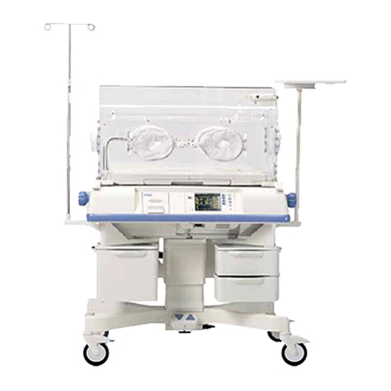
Isolette® Infant Incubator
(Models C2000 and C2000e)
WARNING:
For a full understanding of the performance
characteristics of this equipment, the user
should carefully read this manual before
operating.
Emergency Care · OR/Anesthesia · Critical Care · Perinatal Care · Home Care
Operating Instructions
Because you care
Advertisement
Table of Contents

Related Manuals for Dräger Medical Isolette C2000


Summary of Contents for Dräger Medical Isolette C2000
- Page 1 Isolette® Infant Incubator (Models C2000 and C2000e) WARNING: Operating Instructions For a full understanding of the performance characteristics of this equipment, the user should carefully read this manual before operating. Because you care Emergency Care · OR/Anesthesia · Critical Care · Perinatal Care · Home Care...
-
Page 3: Table Of Contents
Table of Contents Section 1: Definitions Intended Use and Disclaimer Definitions ..............1-1 Symbol Definitions . - Page 4 Section 3: Precautions and Safety Tips Precautions ..............3-1 Electrical Precautions .
- Page 5 Section 5: Instructions for Use Controls, Indicators and Connectors ..........5-1 Incubator .
- Page 6 Alarms ............... 5-13 System Alarms .
- Page 7 Oxygen Sensor Calibration to 100% Oxygen ........5-34 Patient Transport .
- Page 8 Notes:...
-
Page 9: Section 1: Definitions Intended Use And Disclaimer
Section 1 Definitions, Intended Use, and Disclaimer Definitions This manual contains different typefaces and icons designed to improve readability and increase understanding of its content. Note the following examples: • Standard text—used for regular information. • Boldface text—emphasizes a word or phrase. •... - Page 10 • The symbol below indicates “Attention: Consult accompanying documents:” Attention: Consult Accompanying Documents • The symbol below indicates a “Type BF applied part:” Type BF Applied Part – The instrument provides a specified degree of protection against electric shock, particularly the leakage current and reliability of the protective ground connection with a BF-type applied part.
- Page 11 • The symbol below indicates “Consult Accompanying Document on the Battery Weight:” Battery Weight • The symbol below indicates “Consult Accompanying Document on Battery Pack Orientation:” Battery Pack Orientation • The symbol below indicates “Power Failure:” Power Failure • The symbol below indicates “Lock casters when parked on an incline:” Lock Casters •...
- Page 12 • The symbol below indicates “Consult accompanying documents on latch lock/unlock and rail loading:” Latch Lock/Unlock and Rail Loading • The symbol below indicates “Electromagnetic interference:” Electromagnetic Interference Interference can occur in the vicinity of the equipment marked with the Electromagnetic Interference symbol.
-
Page 13: Technical Definitions
Technical Definitions • Incubator temperature—Air temperature at a point 4" (10 cm) above and centered over the mattress surface. • Control temperature—The temperature controller set point selected by the user. • Average incubator temperature—The average of the maximum and minimum incubator temperatures achieved during temperature equilibrium. -
Page 14: Intended Use
Intended Use This manual provides an overall functional description and the instructions for use of the Isolette® Infant Incubator, Models C2000 and C2000e. The Isolette® Infant Incubator, Models C2000 and C2000e should be used only by appropriately trained personnel and under the direction of qualified medical personnel. 1 - 6... -
Page 15: Disclaimer
Disclaimer Dräger Medical cannot be responsible for the performance of the incubator if the user does not operate the unit in accordance with the instructions, fails to follow the maintenance recommendations, or makes any repairs with unauthorized components. Only qualified service personnel should calibrate and repair it. - Page 16 Notes: 1 - 8...
-
Page 17: Section 2: Introduction, Features, And Specifications
Section 2 Introduction, Features, and Specifications Introduction The Introduction subsection provides a system overview and functional description of the Isolette® Infant Incubator, Models C2000 and C2000e. System Overview The Isolette® Infant Incubator, Models C2000 and C2000e is a modular controller-based incubator, which enables simultaneous control of temperature, oxygen and humidity parameters affecting the infant. -
Page 18: Weighing System (Accessory)
Weighing System (Accessory) NOTE: The description in this section does not apply to the EU (Type NAWI) weighing system. Refer to the Isolette® Infant Incubator, Type - NAWI, Weighing System Quick Reference Guide. When installed, the weighing system is located in a platform under the mattress. The scale contains two load beams, which perform the actual weighing function. -
Page 19: Functional Description
Functional Description The temperature, humidity, and oxygen concentration is controlled by the forced air circulation system. A controlled amount of room air, approximately 7 lpm, is drawn through the air intake filter by the motor-driven impeller located in the shell. The impeller internally recirculates air at a much greater flow than that of the fresh gas inflow. -
Page 20: Skin Mode
Skin Mode In the Skin mode, the Up and Down Arrow keys on the controller front panel are used to select the infant temperature from 34.0°C (93.2°F) to 37.0°C (98.6°F). In Temperature Override mode, the temperature can be selected from 37.0°C (98.6°F) to 38.0°C (100.4°F). A temperature sensing probe is attached directly to the skin of the infant. -
Page 21: Features
Features The Features subsection provides a list of the standard and optional features and available accessories for the Isolette® Infant Incubator, Models C2000 and C2000e. Standard Features Standard features include: • Oval access doors with a quiet latch • Trendelenberg mattress tilt mechanism (0° to 12°) •... -
Page 22: Specifications
Specifications The Specifications subsection provides specifications for the standard and optional features and available accessories of the Isolette® Infant Incubator, Models C2000 and C2000e. It also includes regulation, standards and code information for the system. Standard Features Feature Dimension Physical C2000 Depth 67.31 cm (26.5) -
Page 23: Options And Accessories
Feature Dimension Noise level within the hood environment < 47 dBa with 37 dBa or less ambient Air velocity over the mattress < 4"/second (10 cm/second); average of five points at 4" (10 cm) above the mattress Storage temperature -25°C (-13°F) to 60°C (140°F) Storage humidity range 0% to 99% relative humidity non-condensing Carbon Dioxide (CO2) Level... -
Page 24: Humidity System
Feature Dimension Output circuit breaker rating 10 A for 120 V; 5 A for 230 V Input frequency 50/60 Hz (auto sensed by the microprocessor) 45-65 Hz (inverter phase-lock frequency range) Battery type gel cell Operational UPS charge time Full capacity after 8 hours UPS operating time With batteries fully charged, the power available from battery backup is sufficient to maintain a... -
Page 25: Weighing System
Weighing System NOTE: The procedures described in this section do not apply to the EU (Type NAWI) weighing system. Refer to the Isolette® Infant Incubator, Type -NAWI, Weighing System Quick Reference Guide. Feature Dimension Weighing System Weight display range 0 kg (0 lb) to 7 kg (15 lb) Weight display resolution 1.0 g or 0.04 oz Weight display accuracy... - Page 26 Non-Rail Accessory Weight Limitations Feature Dimension Monitor shelf assembly, 11 kg (25 lb) high, C2000e Monitor shelf assembly, 11 kg (25 lb) low, C2000e I.V. pole assembly, 5 kg (11 lb) C2000e Tray assembly, large 17.6 kg (40 lb) Swivel drawer assembly, Tray - 0.91 kg (2 lb) large Drawer - 4.5 kg (10 lb)
-
Page 27: Regulations, Standards, And Codes
Regulations, Standards, and Codes The Isolette® Infant Incubator, Models C2000 and C2000e complies with the following safety standards and performance standards: • EN 60601-1—1990, Medical Electrical Equipment, Part 1: General Requirements for Safety, including Amendments 1, 2, 12 and 13 •... - Page 28 Guidance and Manufacturer’s Declaration—Immunity The C2000 is intended for use in the electromagnetic environment specified below. The customer or user of the C2000 should ensure that the unit is used in such an environment. IEC 60601 Test Electromagnetic Environment— Immunity Test Compliance Level Level Guidance...
- Page 29 Guidance and Manufacturer’s Declaration— Immunity The C2000 is intended for use in the electromagnetic environment specified below. The customer or user of the C2000 should ensure that the unit is used in such an environment. Immunity IEC 60601 Compliance Electromagnetic Environment—Guidance Test Test Level Level...
-
Page 30: Device Classification
Device Classification The Isolette® Infant Incubator, Models C2000 and C2000e meets the requirements for the following classifications: • Class I • Type BF • IPX0—Ordinary equipment • Not AP • Continuous operation 2 - 14... -
Page 31: Section 3: Precautions And Safety Tips
Section 3 Precautions and Safety Tips Precautions This section contains a list of electrical, explosion, EMC, Oxygen and Humidity precautions. Electrical Precautions WARNING: The total electrical current leakage of all items powered through the incubator, including devices on the outlet strip, must be less than 300 µA for 120V AC/100V AC systems and less than 500 µA for 230V AC systems. -
Page 32: Explosion Precautions
SHOCK HAZARD: Batteries can present a risk of electric shock. The following precautions should be taken when working on batteries: remove watches, rings or other metal objects; use tools with insulated handles. SHOCK HAZARD: Some chemical cleaning agents may be conductive and leave a residue that may permit a build-up of conductive dust or dirt. -
Page 33: Emc Precautions
EMC Precautions WARNING: Use of accessories other than those listed and approved for use in this product as original or replacement items may result in increased emissions or decreased immunity. WARNING: The equipment shall not be used adjacent to other devices unless verification of normal operation in the configuration in which it is to be used can be achieved. -
Page 34: Oxygen Precautions
Oxygen Precautions WARNING: Improper use of supplemental oxygen may be associated with serious side effects including blindness, brain damage, and death. The risks vary with each infant. The qualified attending physician should prescribe the method, the concentration, and the duration of oxygen administration. - Page 35 WARNING: Disconnect the incubator from the hospital oxygen source when oxygen is not in use. Failure to do so could result in personal injury or equipment damage. WARNING: A dirty air intake microfilter could affect performance or cause carbon dioxide (CO ) build-up.
-
Page 36: Humidity Precautions
Humidity Precautions WARNING: Higher incubator relative humidity at any given temperature decreases an infant’s evaporative heat loss, and may cause an increase in the infant temperature. Routinely monitor the infant’s rectal and/or axillary temperature according to the attending physician’s orders or Nursery Standing Orders. -
Page 37: Safety Tips
Safety Tips WARNING: Federal law restricts this device to sale by or on the order of a physician. Otherwise, personal injury or equipment damage could occur. [CFR Requirement] WARNING: Thoroughly read and understand the manual prior to use of the incubator. Failure to do so could result in personal injury or equipment damage. - Page 38 WARNING: If airflow passages are not kept clear of obstructions, such as blankets and stuffed animals, during clinical usage, patient safety and incubator performance may be compromised. WARNING: When the access panels are open, a curtain of warm air flows along the length of the mattress toward the top of the access panel openings.
- Page 39 WARNING: Attach the incubator to the stand or the vertical height adjustable stand using the bolts provided. Failure to do so could result in the incubator separating from the stand if sufficiently tilted, particularly with the hood open. Personal injury or equipment damage could occur. WARNING: Never place objects taller than the top of the wheel casters beneath the incubator stand.
- Page 40 WARNING: Accessories such as trays, baskets and shelves should never be overloaded and are not intended to hold an infant. [IHA014] WARNING: Inspect the battery module for possible leakage during service intervals and prior to removal and handling. The battery module is heavy and therefore requires sufficient strength and the proper lift method in order to avoid injury upon removal or installation.
- Page 41 WARNING: Incubator stability can be reduced by both the number of accessories attached, the height and loading of accessories, as well as their position on the rail. It is therefore recommended that rail accessories be kept to a minimum, be adjusted to their lowest usable height and with respect to the end rail, mounted as close to the center of the incubator, as possible.
- Page 42 WARNING: This product has been validated with the accessories and options listed in this manual and found to comply with all relevant safety and performance requirements applicable to the device. It is therefore the responsibility of that person or organization who makes an unauthorized modification, or incorporates an unapproved attachment to the device, to ensure that the system still complies with those requirements.
-
Page 43: Section 4: Installation And Operational Checkout
Section 4 Installation and Operational Checkout Installation Refer to the Isolette® Infant Incubator, Models C2000 and C2000e Service Manual for additional installation, assembly and disassembly procedures. 1. Open the shipping cartons and remove all packing material. 2. Unpackage the hood/shell assembly and stand assembly (see “Unpackaging” on page 4-2). NOTE: If the packaging and/or unit is damaged, contact a local service representative. -
Page 44: Unpackaging
Unpackaging NOTE: When removing the equipment from the cartons, take care not to scratch or otherwise damage unprotected surfaces. C2000 Stand Assembly Carefully lift the stand assembly and remove if from the packaging. C2000e Stand Assembly 1. Prior to removing the stand assembly from the packing box, remove the two 1/2 -13 mounting screws and washers securing one leg of the stand assembly... -
Page 45: Rail Assembly And Accessories Installation
Rail Assembly and Accessories Installation Perform the operation checkout procedure, prior to using the rail system (see “Rail System Operational Checkout” on page 4-19). Rail Assembly To install the rail assembly: 1. Mount a long rail on the tube-type rail supports, engaging the long groove of the long rail on the 2 flanges of the tube-type rail support. - Page 46 7. Align the 3 screw holes on each of the corner brackets with the 3 screw holes on the front and rear long rails. 8. Secure the corner brackets, of the short rail assembly, to the long rails using 6 screws (10-32 x 7/16") and internal tooth washers.
-
Page 47: Rail Accessories
Rail Accessories To install rail accessories refer to the Isolette® Infant Incubator Retrofit and Upgrade Installation Instructions. NOTE: The monitor shelf and I.V. pole can be mounted only on the side rails. The monitor shelf can only be secured on the locating holes towards the rear of the unit, on the side rails. WARNING: Incubator stability can be reduced by both the number of accessories attached, the height and loading of accessories, as well as their position on the rail. -
Page 48: Hood, Shell, And Stand Assembly
WARNING: Failure to adhere to the weight and placement requirements for rail accessories on the rail system can result in personal injury or equipment damage. WARNING: This product has been validated with the accessories and options listed in this manual and found to comply with all relevant safety and performance requirements applicable to the device. -
Page 49: Mattress Restraint Strap Installation
To assembly the hood/shell and stand assemblies: 1. Mount the hood/shell assembly on the stand with the provided screws. 2. Plug the stand power cord into the incubator power cord receptacle. 3. Remove the wing nut, next to the power cord connector, on the stand. 4. -
Page 50: Ups System Installation
9. If necessary, adjust the width of the restraining strap so that it extends the across the mattress. 10. If the incubator is not equipped with a rear (optional) access panel, only perform steps 11 through 13; however, if the incubator is equipped with a rear (optional) access panel, perform steps 13 through 16. 11. -
Page 51: Weighing System (Scale Assembly)
Weighing System (Scale Assembly) (PN 83 600 50) NOTE: The procedures in this section do not apply to the EU (Type NAWI) weighing system. Refer to the Isolette® Infant Incubator, Type -NAWI, Weighing System Quick Reference Guide. To install the weighing system: 1. -
Page 52: Humidity System
Humidity System 83 613 70, 80, 81, 90) 83 615 70, 80, 81 NOTE: The humidity system is normally factory installed. To install the humidity system in the field, refer to the accompanying installation instructions. To install the humidity reservoir: 1. -
Page 53: Oxygen Calibration Fixture
Oxygen Calibration Fixture (PN 83 620 55, 83 620 71) To install the 100% oxygen calibration fixture: 1. Withdraw the sensor module from the hood. 2. Pull out on the clip located on the left side of the module, and remove the module from the hood. 3. -
Page 54: Operational Checkout
Operational Checkout Perform the operational checkout procedure before the incubator is first placed into service and after any disassembly for cleaning or maintenance. NOTE: For units equipped with the rail system and accessories, remove any accessories that interfere with the checkout procedure, and replace when completed. - Page 55 5. Check the Skin mode of operation. a. Insert a skin probe into the skin probe 1 connector of the sensor module. b. Place the skin probe 10 cm (4") above the center mattress. c. Set the skin set temperature to 35°C (95°F). d.
-
Page 56: Hood/Shell Operational Checkout
9. Check the Connect Skin 1 Probe alarm. a. While operating in the Air mode, disconnect the skin probe 1, and then select the Skin mode. b. Verify that the Connect Skin 1 Probe alarm sounds. Hood/Shell Operational Checkout To check the hood/shell operation: 1. - Page 57 3. Rotate the outer ring of the iris entry ports. The iris opens and closes as rotation is continued through 360°. 4. Check the access door latches and gaskets. a. Press the door release of each access door and verify that the access door swings open. b.
- Page 58 a. Rotate the pawl latches, and open the front access panel. b. Pivot the front access panel to the full open position (hanging straight down). c. Slide out the mattress tray to the fully extended position. d. Carefully lean on the mattress tray to ensure it is properly supported and provides a firm infant platform.
-
Page 59: Vha Stand Operational Checkout
10. Check the x-ray tray: a. Rotate the pawl latches, and open the front access panel. b. Pivot the front access panel to the full open position (hanging straight down). c. Slide out the x-ray tray. d. Check the tray for any defects. e. -
Page 60: Ups System Operational Checkout
Perform this operational checkout procedure along with the operational checkout procedure for the controller before placing the incubator into service, and after any disassembly or maintenance. To check the VHA stand: 1. Make sure the system is fully powered (see “System Start-Up and Shut- Down”... -
Page 61: Test Battery Back-Up Function
Test Battery Back-up Function 9. Unplug the AC power cord, at the electronics module, from the AC power source. 10. Verify the battery back-up audio beeps twice every 8 seconds. 11. Verify the AC LED turns off. 12. Quickly press the On/Off/Test switch (<1 second) to silence the audio. 13. -
Page 62: Humidity System Operational Checkout
Humidity System Operational Checkout PTIONAL EATURE To install the humidity reservoir: 1. Make sure the reservoir is full. 2. Place the probe of a calibrated hygrometer inside the hood at the center of the mattress. 3. Pre-warm the incubator to 35.0°C (95.0°F). 4. -
Page 63: Section 5: Instructions For Use
Section 5 Instructions for Use Controls, Indicators and Connectors The Controls, Indicators and Controls subsection lists and describes the controls, indicators and connectors on the system. Incubator Below are the incubator controls, indicators and connectors: Incubator Controls Power switch: The Main Power (On/Off) switch is used to provide power for the main incubator functions. -
Page 64: Softkeys
Parameter Selection keys: The Parameter Selection keys enable the user to select parameter and menu options at the various displays. Softkeys Air softkey: The Air softkey selects the Air mode, at Display 1. Skin softkey: The Skin softkey selects the Skin mode, at Display 1. Humidity softkey: The Humidity softkey selects the Humidity display, at Display 1. -
Page 65: Incubator Indicators
Display softkey: The Display softkey is available at the Trend display. When pressed, it selects one of following trends to display in the Trend/Alarm window: Air, Skin 1, Skin 2, Oxygen%, Humidity%, Heater Power% or Weight Gain. Store softkey: The Store softkey is available at the Weight display. When pressed, it stores the infant weight for trending in the Trend/Alarm window. -
Page 66: Incubator Connectors
Incubator Connectors Controller Interface Connector The controller interface connector provides communication between the controller and sensor module. Serial Port WARNING: Devices connecting to the serial port must be compliant with EN 60601-1-2, the EMC requirement for Medical Devices. Failure to do so could result in personal injury or equipment damage. -
Page 67: Sensor Module
Sensor Module Below are the sensor module controls, indicators and connectors: Sensor Module Controls There are no controls on the sensor module. Sensor Module Indicators The sensor module has one alarm indicator. Sensor Module Connectors The following connectors are found on the sensor module: •... -
Page 68: Foot Pedal Controls
Main Circuit Breaker Locations Incubator Model Stand Configurations Main Circuit Breaker Locations Models C2000 and C2000e Fixed Height stands without UPS sys- On the stand column below the AC receptacles tems (convenience outlet strip) Model C2000e only Fixed height stands with UPS systems On the UPS electronic control module Model C2000e only Variable height adjustable (VHA) At the rear, below the stand column... -
Page 69: Ups Electronic Module
UPS Electronic Module The UPS electronic module is mounted in the pedestal cover of units equipped with UPS systems. UPS Electronic Module Controls The exposed panel of the UPS electronic module contains the following controls: • Resettable circuit breaker • Inverter On/Off/Test switch (located on the UPS electronic module display panel) UPS Electronic Module Indicators The front panel of the UPS electronic module contains the... -
Page 70: Ups Electronic Module Connectors
Uninterruptible Power Supply (UPS) Indicator Status Mode System Condition Fault Bypass Inv. AC LED Beep Bypass Normal Line — — Line Normal Line — — — Line or Overload — — On (Line) Continuous Backup Backup Normal Battery — — —... -
Page 71: Displays
Displays The controller displays supports the following windows: Temperature, Trend/Alarm window, Humidity window and Oxygen window. If the oxygen, humidity and scale options/accessories are installed, the associated data are displayed when the control is enabled. The UPS electronic module is also equipped with a front display panel (see “UPS Electronic Module” on page 5-7.) Temperature Window The Temperature window also displays the... -
Page 72: System Displays
System Displays The controller has two system displays, Display 1 and Display 2, from which the following displays can be accessed: • Temperature • Trend • Weight • Oxygen • Humidity Temperature Displays Access to the temperature displays is made available at Display 1. The temperature displays enable the user to: •... -
Page 73: Oxygen Display
Oxygen Display Access to the oxygen display is made available at Display 1. The Oxygen display enables the user to: • Activate the oxygen system • Select the oxygen control set point • Calibrate the oxygen sensor Humidity Display Access to the humidity display is made available at Display 1. The humidity display enables the user to: •... -
Page 74: Factory Default Settings
Factory Default Settings For non-UPS systems, in the event of a power failure lasting 10 min or less, the set points and operating mode are retained. For UPS systems, in the event of a power failure, the incubator operating time is determined by the amount of battery charge remaining when the event occurs. -
Page 75: Alarms
Alarms An alarm is signaled whenever a condition, which could be potentially hazardous, is detected. System Alarms System alarm conditions are always signaled with a visual and audible indication and an appropriate message in the Trend/Alarm window. In the event that two or more system alarms occur simultaneously, or one after the other, the messages that describe the alarms are presented in sequence. - Page 76 Alarm Procedural Alarm Message Description Silence Silence Controller Failure 9 This alarm occurs when a failure is detected with real time clock. Controller Failure 10 This alarm occurs when a failure is detected with the watchdog timer test. Controller Failure 11 This alarm occurs when a failure is detected with the relay test.
- Page 77 Alarm Procedural Alarm Message Description Silence Silence Sensor Module Failure 3 N/A This alarm occurs when the controller detects a sensor module fan is not rotating. Sensor Module Failure 4 N/A This alarm occurs when the controller detects a sensor module analog-to-digital failure. Sensor Module Failure 5 N/A This alarm occurs when the controller detects an oxygen multiplexer calibration failure.
- Page 78 Alarm Procedural Alarm Message Description Silence Silence Low Skin Temperature This alarm occurs when the indicated displayed temperature differs from the set temperature by <1.0°C or 0.5°C (user selectable). Air Probe Failed This alarm occurs when one of the three ther- mistors in the sensor module differ from the other two by 0.8°C or all three thermistors have a measurement error exceeding acceptable lim-...
-
Page 79: Ups Alarms
Alarm Procedural Alarm Message Description Silence Silence Oxygen Solenoid Fail This alarm occurs when the oxygen solenoid voltage is not within limits. Slide In Sensor This alarm occurs after calibration is completed but the sensor module was not returned to the hood position. - Page 80 Alarm Messages Description Check Skin1 Probe This message is displayed in the Air mode if the Skin1 probe is electri- cally open or shorted; or if in the air mode the two Skin1 probe ther- mistors deviate by more than 0.8 °C; or if in either Air or Skin mode, the Skin1 probe is <...
-
Page 81: Infant Placement
Infant Placement To place an infant in the incubator, perform the following: WARNING: Prior to placing the infant in the incubator, pre-warm the incubator to the temperature prescribed by the attending physician, or according to nursing protocol. 1. Pre-warm the incubator. 2. -
Page 82: Operating Instructions
Operating Instructions The Operating Instructions subsection describes the procedures required to operate the incubator, stand, options and accessories. System Start-Up and Shut-Down Below are the initial start-up procedures for UPS and non-UPS systems: System Start-up Initial Start-up for systems without UPS To power up the system: 1. -
Page 83: Recovery From Power Failure (Non-Ups Systems)
NOTE: If the unit fails the self-test, the alarm sounds, and one or more of the following messages appears in the Trend/Alarm window, refer the unit to service: Controller Failure 1 through 13, or Check Settings. 6. Select the desired system options, parameters and operating modes at the incubator controller (see “System Configuration”... -
Page 84: System Configuration
System Configuration The System Configuration menu enables the user to access the system-configurable parameters. Refer to the table below: System Configuration Menu Up/Down Arrow Key Display Selection Key Selections Default Setting Selections Humidity option Yes/No Oxygen option Yes/No Oxygen calibration level 100%/21% Skin temperature alarm limit 1.0°C/.05°C... -
Page 85: Variable Height Adjustment
8. Select the required setting(s) using the Up Arrow and Down Arrow keys. 9. Press the Alarm Silence/Reset key, to exit the Set Configuration menu. Variable Height Adjustment WARNING: When raising or lowering the incubator, the operator should ensure that both equipment and appendages are clear of the unit’s travel path. -
Page 86: Skin Mode
2. Set the air temperature to the prescribed setting. a. Press the Up Arrow key to raise the set temperature from 20°C (68°F) to 37.0°C (98.6°F) in 0.1° increments. In Temperature Override mode, press the Up Arrow key to raise the set temperature from 37.0°C (98.6°F) to 39.0°C (102.2°F). -
Page 87: Skin Probe Attachment
4. To confirm the Skin Set Temperature setting and return to Display 1, press the Home softkey. NOTE: Once stabilized, the incubator temperature stays within 0.5°C of the set temperature. 5. To lock the keypad, press the Keylock key. Skin Probe Attachment NOTE: The sensor module is equipped to accept two skin probes. -
Page 88: Data Trends
NOTE: When a second skin probe is connected to the sensor module while operating in Skin mode, an alarm sounds, and the Remove Skin 2 Probe alarm is activated. Data Trends To select a trend display for viewing, perform the following steps: 1. -
Page 89: Scale Measurements
Scale Measurements NOTE: The procedures described in this section do not apply to the EU (Type NAWI) weighing system. Refer to the Isolette® Infant Incubator, Type -NAWI, Weighing System Quick Reference Guide. Methods and Techniques to Obtain Accurate Infant Weight are described below: •... -
Page 90: Re-Weigh
9. To return to Display 2, press the Home key. Re-weigh 1. To re-weigh the infant without removing or adding anything to the mattress, press the Weight softkey on Display 2. 2. If any objects are added or removed from the mattress, or a power failure occurs, refer to “Initial Weigh”... -
Page 91: Oxygen Control Set Point
Oxygen Control Set Point To set the oxygen control set point in accordance with the attending physician recommendations: 1. Activate the Oxygen mode (see “Oxygen Control” on page 5-28). 2. Adjust the oxygen set point: a. Press the Up Arrow key to raise the set point from 21% to 65%. b. -
Page 92: Humidity Control Set Point
Humidity Control Set Point 1. Activate the humidity system (see “Humidity Mode” on page 5-29). NOTE: If no keys are pressed within 15 s of selecting the Humidity display, the display automatically reverts to Display 1. 2. Adjust the humidity set point. a. -
Page 93: X-Ray Tray Usage
X-Ray Tray Usage WARNING: For infant safety, do not leave the infant unattended when the access panel is open. Personal injury could occur. To use the x-ray tray, perform the following steps: 1. For units equipped with the rail system, remove any accessories that may interfere with front access panel movement. -
Page 94: Calibration
Oxygen Concentration Guide Oxygen Supply Approximate Oxygen% 3 lpm 30% - 45% 6 lpm 46% - 60% 9 lpm 50% - 70% 12 lpm 55% - 75% 15 lpm 60% - 80% Calibration Scale Calibration NOTE: The procedures described in this section do not apply to the EU (Type NAWI) weighing system. Refer to the Isolette®... -
Page 95: Oxygen Sensor Calibration
Oxygen Sensor Calibration NOTE: Only single point calibration is required. NOTE: If the message Cal Required is displayed, calibrate the oxygen control system. At a minimum, daily calibrations are recommended. NOTE: If the sensor module cable is disconnected from the shell connector during operation, the message Cal Required is displayed to indicate that the oxygen control system must be calibrated. -
Page 96: Oxygen Sensor Calibration To 100% Oxygen
Oxygen Sensor Calibration to 100% Oxygen 1. To perform the 100% oxygen calibration procedure, install the 100% oxygen calibration fixture on the hood (see “Oxygen Calibration Fixture” on page 4-11). 2. Verify the oxygen calibration level setting (21% or 100%) at the System Configuration Menu (see “System Configuration”... -
Page 97: Patient Transport
Patient Transport With batteries fully charged, the power available from battery backup is sufficient to maintain an Isolette® Infant Incubator, Model C2000e in operation for 30 min in a 20°C ambient at a set point of 39°C in the Air mode, without oxygen or humidity control, or additional loads drawn from the accessory outlets. - Page 98 WARNING: Prior to transport, always ensure the mattress is level, i.e., not in the Trendelenburg or Reverse Trendelenburg position. 6. Ensure the mattress is in the flat position. 7. Secure the infant using the restraining straps with the slotted mattress tray. NOTE: The straps should be placed over the infant and the ends firmly pressed together.
- Page 99 WARNING: Do not plug the AC input supply power cord of the uninterruptible power supply (UPS) system into any of the output receptacles on the incubator stand. This is a safety hazard and may cause irreparable damage to the UPS system. 12.
- Page 100 Notes: 5 - 38...
-
Page 101: Section 6: Cleaning, Maintenance, And Replacement Parts
Section 6 Cleaning, Maintenance, and Replacement Parts Cleaning WARNING: Follow the product manufacturer’s cleaning instructions. Failure to do so could result in personal injury or equipment damage. WARNING: When performing cleaning and maintenance procedures, confirm that the oxygen supply is turned off and that the equipment is disconnected from the oxygen supply. -
Page 102: Steam Cleaning
Steam Cleaning Do not use any steam cleaning device on the unit. Excessive moisture can cause damage. Stain Cleaning To remove difficult spots or stains, Dräger Medical recommends the use of standard household cleansers and a soft bristle brush. To loosen heavy, dried-on soil, saturation of the spot could be required. Disinfecting •... -
Page 103: Mattress Tray, X-Ray Tray, Main Deck, Scale (Optional)
Mattress Tray, X-Ray Tray, Main Deck, Scale (optional) 2. Disconnect the cables from the sensor module. 3. Slowly raise the hood. 4. Remove the mattress. 5. If the incubator is equipped with a weighing scale, perform steps 6 through 8; otherwise continue at step 8. -
Page 104: Air Intake Microfilter
20. Pull the access door gaskets from each side of the hood to remove them. 21. Pull the tubing access grommets from each side of the hood. 22. Remove the disposable iris entry port sleeves from the retainer rings. 23. Wipe the retainer rings clean. 24. -
Page 105: Sensor Module, Hood, And Inner Walls
Sensor Module, Hood, and Inner Walls CAUTION: Alcohol can cause crazing (small stress cracks) of the clear acrylic. Do not use alcohol for cleaning. Equipment damage could occur. CAUTION: Do not expose the clear acyrlic to direct radiation from germicidal lamps. Ultraviolet radiation from these sources can cause cracking and/or crazing of the acrylic surface. -
Page 106: Air Intake Microfilter
Do not immerse the heater assembly in liquid. NOTE: The evaporator raises the temperature of the water to the boiling point. Any waterborne bacteria are killed, thus preventing transfer into the patient compartment. Therefore, there is no need to remove the metering valve and the evaporator assembly for cleaning or sterilization. -
Page 107: Uninterruptible Power Supply (Ups) Air Filter
Uninterruptible Power Supply (UPS) Air Filter NOTE: The filter can be inspected and cleaned during operation. However it is recommended that this procedure be performed without a patient in the system. 1. Grasp the handle and firmly pull the filter cartridge until it is removed from the UPS electronic module. - Page 108 b. Fold back, and slip the larger elastic band over the outer ring of the port housing. c. Rotate the outer ring to close. If properly installed, the sleeve opens again when rotation is reversed. 10. Install the tubing access grommets into the front and rear edges of each side of the hood.
-
Page 109: Maintenance
Maintenance WARNING: Only facility-authorized personnel should perform preventive maintenance or troubleshooting on the Isolette® Infant Incubator, Models C2000 and C2000e. Preventive maintenance performed by unauthorized personnel could result in personal injury or equipment damage. Facility-authorized personnel should routinely inspect the patient compartments for signs of breakage and replace assemblies before placing the incubator into service. -
Page 110: Ups Electronics Module Maintenance
UPS Electronics Module Maintenance The module houses a dust filter cartridge that can be easily cleaned. The filter should be inspected during each operational checkout and cleaned as required. In addition, every three months or as appropriate the filter and electronics module air inlet holes should be cleaned (see “Uninterruptible Power Supply (UPS) Air Filter”... -
Page 111: Replacement Parts
Replacement Parts This section provides a listing of replacement parts, accessories, and single-use items. Parts not listed here should be replaced by qualified service personnel only. NOTE: Refer to the Isolette® Infant Incubator Upgrade and Retrofit Kit Installation Instructions to upgrade C2000 and C2000e incubators. - Page 112 Part Number Description Oxygen 83 620 23 Oxygen assembly, National Institute of Standards and Technology (NIST) fitting 83 620 30 Cell, oxygen 83 620 50 Oxygen assembly, green diameter index safety system (DISS) 83 620 51 Oxygen assembly, green (hose) 83 620 52 Oxygen assembly, white (hose) 83 620 53...
- Page 113 Part Number Description 85 441 52 Drawer housing assembly, shallow, short (Model C2000e only) 85 441 53 Drawer housing assembly, shallow, long (Model C2000e only) 85 441 56 Swivel drawer assembly, large, C2000e (Model C2000e only) 85 441 60 Drawer housing assembly, deep, short (Model C2000e only) 85 441 61 Drawer housing assembly, deep, long...
- Page 114 NOTES: 6 - 14...
-
Page 115: Section 7: Troubleshooting
Section 7 Troubleshooting General WARNING: Only facility-authorized personnel should perform preventive maintenance or troubleshooting on the Isolette® Infant Incubator, Models C2000 and C2000e. Preventive maintenance performed by unauthorized personnel could result in personal injury or equipment damage. If the fault cannot be located, refer the unit to qualified service personnel. Symptom, Cause, and Remedy For troubleshooting of the incubator, refer to the table below: Troubleshooting... - Page 116 Symptom Possible Cause Remedy An iris entry port sleeve is open or Check the installation of the iris improperly installed. entry port. A tubing access port is not Check the installation of the properly installed. tubing access port. The air intake microfilter cover is Check and secure the air intake not properly secured.
- Page 117 Symptom Possible Cause Remedy A sensor module alarm is acti- A sensor module malfunction If the alarm persists, turn the incu- vated. occurred. bator off and remove it from ser- vice The Sensor Out of Position alarm The sensor module is not in the Verify proper positioning of the is activated.
- Page 118 Symptom Possible Cause Remedy The Cal Fail message is dis- The servo-controlled oxygen sys- Repeat the calibration procedure. played. tem failed to calibrate. If the calibration procedure fails the second time, refer the unit to qualified service personnel. The Not Installed message is dis- The servo-controlled oxygen Install the oxygen and/or humidity played.
- Page 120 Manufactured by: EC Representative: Draeger Medical Infant Care, Inc. Dräger Medical AG & Co. KGaA 330 Jacksonville Road Germany Hatboro, PA 19040 USA Moislinger Allee 53 - 55 USA and Canada: (800) 437-2437 D-23542 Lübeck http://www.draegermedical.com Tel: 01 (451) 882 - 0 Fax: 01 (451) 882-2080 http://www.draeger.com Part number Revisions...
Need help?
Do you have a question about the Isolette C2000 and is the answer not in the manual?
Questions and answers