Dräger Medical Fabius GS Technical & Service Manual
Inhalation anesthesia machine
Hide thumbs
Also See for Fabius GS:
- Assembly and installation manual (8 pages) ,
- Technical & service manual (366 pages) ,
- Technical & service manual (350 pages)

Related Manuals for Dräger Medical Fabius GS


Summary of Contents for Dräger Medical Fabius GS
- Page 1 Technical Service Manual Fabius GS Inhalation Anesthesia Machine Revision 3.0 5330.500 9036095 Because you care Emergency Care • Perioperative Care • Critical Care • Perinatal Care • Home Care...
-
Page 3: Table Of Contents
Contents General Notes Symbols and Definitions ......................4 Function Description General Information about the Fabius GS Function diagram of Fabius GS Battery backup Fabius GS piping diagram Function description of gas box SORC (Sensitive Oxygen Ratio Controller) Cosy 2 breathing system Ventilation mode ........................ - Page 4 Contents Electrical block diagram Function description: Control PCB Control panel assembly FiO2 Measurement Respiratory Flow Measurement Gas flow rate measurement Anesthetic vaporizer(s) Leak test 17.1 System leak test ........................49 17.2 Patient leak test ........................49 Annex Parts catalog Technical Information...
- Page 5 General...
-
Page 7: General
Fabius GS General Notes This Technical Documentation conforms to the IEC 60601-1 standard. Read each step in every procedure thoroughly before beginning any test. Always use the proper tools and specified test equipment. If you deviate from the instructions and/or recommendations in this Technical Documentation, the equipment may operate improperly or unsafely, or the equipment could be damaged. -
Page 8: Symbols And Definitions
General Fabius GS Symbols and Definitions This symbol indicates a warning. This symbol indicates tips and useful information. This symbol is used to alert against unsafe practices when handling electrostatic sensitive devices (ESD). Definitions according to German standard DIN 31051:... -
Page 9: Function Description
Function Description... -
Page 11: General Information About The Fabius Gs
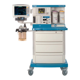
Breathing system – Pneumatic assembly – Ventilator – Vaporizers – Trolley Monitoring, electrical connections and gas connections as shown in Figure Figure Figure 3, and Figure Figure 1 Front view of Fabius GS anesthesia system, for legend see Table 5330.500... - Page 12 Function description Fabius GS Table 1 Legend to Figure 1 Name Trolley O2 flush Cosy 2 breathing system Ventilator Oxygen flowmeter (auxiliary) Display Control panel Vaporizers Cylinder Pressure Gauges Pipeline Pressure Gauges Flow Control Valves Total fresh gas flowmeter 5330.500...
- Page 13 Fabius GS Function description Figure 2 Rear view showing interface panel and power entry, for legend Table 2 Table 2 Legend to Figure 2 Name Serial communication ports (only one is shown) Tube connection for PEEP valve Tube connection for APL bypass valve...
- Page 14 Function description Fabius GS Name ON/OFF switch Battery fuse Figure 3 Rear view showing gas pipeline and PIN index cylinder connec- tions, for legend see Table 3 Table 3 Legend to Figure 3 Name Pipeline tube connections N2O or AIR PIN index cylinder connections...
- Page 15 Fabius GS Function description Figure 4 Rear view showing gas pipeline and cylinder connections (units without PIN index cylinder connections), for legend see Table 4 Table 4 Legend to Figure 4 Name Pipeline tube connections N2O cylinder connection O2 cylinder connection...
-
Page 16: Function Diagram Of Fabius Gs
Function description Fabius GS Function diagram of Fabius GS Figure 5 Function diagram of Fabius GS - Cosy 2 breathing system 5330.500... - Page 17 Fabius GS Function description Figure 6 Function diagram of Fabius GS - Cosy 2.5 (2.6) breathing system 5330.500...
-
Page 18: Battery Backup
Fabius GS Battery backup Fabius GS backup power is provided by two series-connected 12 V recharge- able batteries. These batteries remain on charge as long as the machine is plugged into an active AC outlet. Should power supply fail while the machine is in operation, the batteries will allow the machine to continue operating for a minimum of 45 minutes, provided that the batteries are fully charged. -
Page 19: Function Description Of Gas Box
Fabius GS Function description Function descrip- The supply gases flow through the filters and non-return valves in the gas tion of gas box inlet assembly. Pipeline supply pressures are indicated on pipeline pressure gauges located on the flowmeter assembly. Cylinder pressure gauges are located on the trolley assembly. -
Page 20: Sorc (Sensitive Oxygen Ratio Controller)
Function description Fabius GS Figure 10 Gas box function diagram, part 2 SORC (Sensitive The SORC is a control element that functions like an N2O shut-off device and Oxygen Ratio Con- ensures a vital O2 concentration in the fresh gas. In the event of an O2 short-... - Page 21 Fabius GS Function description Figure 11 SORC function diagram, part 1 The O2 and N2O flows are adjusted with the flow control valves. Restrictors located at the outlets of the SORC generate back-pressures. These back-pressures exert a force on the control diaphragms of the SORC.
-
Page 22: Cosy 2 Breathing System
Function description Fabius GS Table 5 Legend to Figure 12 Name Control diaphragms Restrictors N2O non-return valve Operating-point adjusting screw Flow control valves Cosy 2 breathing The Cosy 2 breathing system allows three modes of patient ventilation: system – Manual ventilation and spontaneous breathing –... - Page 23 Fabius GS Function description Figure 13 Cosy 2 breathing system, for legend see Table 6 Table 6 Legend to Figure 13 Name Expiratory connection Flow sensor (Spirolog) (not shown) PEEP/Pmax valve MAN/SPONT APL valve APL Bypass valve Fresh-gas decoupling valve...
- Page 24 Function description Fabius GS Name Pressure sensor connection Breathing bag terminal and standby holder for Y-piece Breathing bag hook Inspiratory connection Inspiratory valve and O2 sensor connection Anesthesia monitor return line (only for systems outside the USA) Expiratory valve Figure 14 Cosy 2.5 (2.6) breathing system, for legend see...
- Page 25 Fabius GS Function description Name PEEP/Pmax valve Anesthesia monitor return line (only for systems outside the USA) MAN/SPONT APL valve APL Bypass valve Fresh-gas decoupling valve Fresh-gas port Ventilator port Anesthetic gas scavenging port Absorber Pressure sensor connection Breathing bag terminal and standby holder for Y-piece...
-
Page 26: Ventilation Mode
Function description Fabius GS Ventilation mode Figure 15 Functional diagram of the ventilation mode, for legend see Table Table 8 Legend to Figure Figure Figure Figure Figure Figure Figure Figure Figure Figure Fig- Figure Figure 27 Name Breathing bag Fresh gas inlet... -
Page 27: Function Description: Manual Ventilation
Fabius GS Function description Name Flow sensor PEEP/Pmax valve Expiratory valve APL bypass valve APL valve Exhaust valve Absorber Function descrip- tion: Manual ventila- tion Manual ventilation: Gen- During manual ventilation, the APL valve is set to the “MAN” position. The eral safety valve of the ventilator is activated. - Page 28 Function description Fabius GS Figure 16 Manual ventilation (inspiration) - Cosy 2 breathing system; for legend see Table 8 5330.500...
- Page 29 Fabius GS Function description Figure 17 Manual ventilation (inspiration) - Cosy 2.5 (2.6) breathing sys- tem; for legend see Table 8 Manual ventilation: Expira- During expiration, the inspiratory valve remains closed thus preventing the tion – Cosy 2 breathing expiratory gas from flowing back into the inspiratory branch.
- Page 30 Function description Fabius GS Figure 18 Manual ventilation (expiration) - Cosy 2 breathing system; for leg- end see Table 8 Manual ventilation: Expira- During expiration, the inspiratory valve remains closed thus preventing the tion – Cosy 2.5 (2.6) expiratory gas from flowing back into the inspiratory branch.
-
Page 31: Function Description: Spontaneous Breathing
Fabius GS Function description Figure 19 Manual ventilation (expiration) - Cosy 2.5 (2.6) breathing system; for legend see Table 8 Function descrip- tion: Spontaneous breathing Spontaneous breathing: A prerequisite for spontaneous breathing is that the patient is supplied with a General sufficient amount of fresh gas. - Page 32 Function description Fabius GS Figure 20 Spontaneous (inspiration) - Cosy 2 breathing system; for legend Table 8 5330.500...
- Page 33 Fabius GS Function description Figure 21 Spontaneous (inspiration) - Cosy 2.5 (2.6); breathing system; for legend see Table 8 Spontaneous breathing: During expiration, the inspiratory valve remains closed thus preventing the Expiration – Cosy 2 expiratory gas from flowing back into the inspiratory branch.
- Page 34 Function description Fabius GS Figure 22 Spontaneous (expiration) - Cosy 2 breathing system; for legend Table 8 Spontaneous breathing: During expiration, the inspiratory valve remains closed thus preventing the Expiration – Cosy 2.5 (2.6) expiratory gas from flowing back into the inspiratory branch.
-
Page 35: Function Description: Volume/Pressure Control Ventilation Mode
Fabius GS Function description Figure 23 Spontaneous (expiration) - Cosy 2.5 (2.6); breathing system; for legend see Table 8 Function descrip- tion: Volume/pres- sure control ventilation mode Volume control ventilation A prerequisite for volume control ventilation is that the patient is supplied with mode: General a sufficient amount of fresh gas. - Page 36 Function description Fabius GS The position numbers mentioned in this chapter refer to Figure 24 Figure The pressure generated by the piston 4 of the ventilator closes the fresh-gas decoupling valve 3. The gas mixture (expiratory gas and fresh gas 2) flows through the inspiratory valve 5, the O2 sensor 7, the inspiratory hose 8, and the Y-piece 9 into the lung 10.
- Page 37 Fabius GS Function description Figure 25 Volume control ventilation (inspiration) - Cosy 2.5 (2.6); breathing system; for legend see Table 8 Volume/pressure control During expiration, the inspiratory valve remains closed thus preventing ventilation mode: Expira- rebreathing into the inspiratory branch.
- Page 38 Function description Fabius GS Figure 26 Volume control ventilation (expiration) - Cosy 2 breathing sys- tem; for legend see Table 8 5330.500...
-
Page 39: Cosy 2 Absorber
The ventilator is located in a swing-out compartment at the left side of the Fabius GS. The ventilator is connected to the Cosy 2 via a tube. Fresh gas is delivered to the patient by a piston that is driven by a motor and ball-screw arrangement. - Page 40 Function description Fabius GS The ventilator motor is controlled by the Control PCB. A light barrier on the ventilator signals the Control PCB when the piston reaches its lower limit. An incremental encoder on the motor shaft determines the number of revolutions and provides piston travel information to the control PCB.
- Page 41 Fabius GS Function description Figure 28 Ventilator (piston shown in ‘down’ position), for legend see Table Table 10 Legend to Figure 28 Name Cylinder Safety valve Auxiliary air valve Ventilator pressure sensor line Vacuum line to the pneumatic assembly Upper diaphragm...
-
Page 42: Safety Valve
Valve disc Auxiliary air valve The auxiliary air valve allows the patient to spontaneously breathe ambient air should the medical gas supply and/or Fabius GS fail. The opening pres- sure of this valve is listed in the table below. Table 12... -
Page 43: Pneumatics
APL bypass valve control. PEEP/Pmax valve When the Fabius GS is operating in the automatic mode, the pump on the control pneumatic assembly is running, and the electronic PEEP valve is actuated by the Control PCB. -
Page 44: Apl Bypass Valve Control
Fabius GS Figure 31 Pneumatic control system schematic APL bypass valve When the Fabius GS is operating in the automatic mode, the pneumatic control assembly provides a vacuum signal to hold open the APL bypass valve in the breathing system. The V2 reservoir and filter provide noise damping, and the variable restrictor is used to set the vacuum level in the range of –150 to –240... -
Page 45: Electrical Block Diagram
Fabius GS Function description Electrical block dia- gram Figure 32 Electrical block diagram Function descrip- The Control PCB contains the following functions: tion: Control PCB – Motor control and monitoring – Measurement of O2 and flow parameters – Provision of one or two serial interfaces –... -
Page 46: Control Panel Assembly
Function description Fabius GS Figure 33 Controller functional block diagram Control panel The control panel consists of a 320 x 240 pixel graphical display, a table lamp assembly with six LEDs, a membrane keypad, rotary encoder and speaker. Data and power for the display comes from the Control PCB via a 20-conduc- tor ribbon cable. - Page 47 Fabius GS Function description Figure 34 Control panel block diagram Figure 35 Fabius GS control panel (“Standby” screen shown), for legend Table 14 Table 14 Legend to Figure 35 Item Function Selects volume control ventilation mode. Refer to Instructions for Use manual Selects pressure control ventilation mode.
-
Page 48: Fio2 Measurement
Function description Fabius GS Item Function Soft keys: activate the corresponding function that appears on screen above the key For setting alarm limits Refer to Instructions for Use manual Setup key: activates sub-screens for monitoring functions. Refer to Instructions for Use manual Home key: returns display to main screen shown before standby Rotary encoder: moves the cursor on the screen;... -
Page 49: Respiratory Flow Measurement
Fabius GS Function description Table 15 Legend to Figure 36 Name Teflon membrane Gold cathode A Lead anode Temperature compensation resistors Alkaline electrolyte Gold cathode B The O2 to be measured diffuses through the Teflon membrane, undergoes a chemical reaction at the gold cathodes (negative) and produces lead oxide and water at the lead anode (positive). -
Page 50: Gas Flow Rate Measurement
Function description Fabius GS Figure 37 Respiratory flow sensor, for legend see Table 16 Table 16 Legend to Figure 37 Name “A” Platinum wire “A” “B” Platinum wire “B” Gas flow rate mea- The gas flow sensors operate on the principle of specific heat for individual surement gases. -
Page 51: Anesthetic Vaporizer(S)
Fabius GS Function description Table 17 Legend to Figure 38 Name Tube connector Electronic components Electrical connection Gas outlet port (to manifold) Mounting pole Heated chamber Gas inlet assembly Figure 39 Gas flow through sensors, for legend see Table 18... - Page 52 Function description Fabius GS 5330.500...
-
Page 53: Leak Test
Fabius GS Function description Leak test The leak test menu screen instructs the user how to begin the leak test. After preparing the machine, the user initiates the test. If the size of the leak is outside the tolerance range, an appropriate message is displayed to tell the user that the system leak test has failed. - Page 54 Function description Fabius GS The result of the “patient leak test” is displayed after each test. The result of the “system leak test” is displayed only if the value is outside the tolerance range. Otherwise only OK will be displayed.
- Page 55 Annex Parts catalog Technical Information...
- Page 57 Parts catalog Fabius GS Revision: 2005-09-14 09:18:30 5330.500 Because you care Emergency Care - Perioperative Care - Critical Care - Perinatal Care - Home Care...
- Page 59 Suction hoses Parts catalog Item Qty.u Part No. Description Qty. Remark M35015 AGS-SCAVANGER HOSE 0,5M 1.000 M33297 AGS-SCAVANGER HOSE 1,5M 1.000 M33298 AGS-SCAVANGER HOSE 3M 1.000 M33299 AGS-SCAVANGER HOSE 5M 1.000 Items that are shown in the illustration but are not listed below the illustration are not available as spare parts 5330.500 Revision: 2005-09-14 09:18:30...
- Page 60 Plugs Parts catalog Item Qty.u Part No. Description Qty. Remark G60580 AGSS PROBE/STRAIGHT-TYPE1/ EN 1.000 G60495 AGSS ANGLE PROBE / TYPE 1 / EN 1.000 Items that are shown in the illustration but are not listed below the illustration are not available as spare parts 5330.500 Revision: 2005-09-14 09:18:30...
- Page 61 Plugs Parts catalog Item Qty.u Part No. Description Qty. Remark G60440 ANAESTH.WASTE GAS PROBE 45 1.000 Items that are shown in the illustration but are not listed below the illustration are not available as spare parts 5330.500 Revision: 2005-09-14 09:18:30...
- Page 62 ventilator Parts catalog Item Qty.u Part No. Description Qty. Remark 2600650 DIAPHRAGM,CUP 1.000 8604319 patient assembly 1.000 2M08777 O-RING SEAL 1.000 Items that are shown in the illustration but are not listed below the illustration are not available as spare parts 5330.500 Revision: 2005-09-14 09:18:30...
- Page 63 absorber Parts catalog Item Qty.u Part No. Description Qty. Remark M29320 ABSORBER CICERO 1.000 M29999 ABSORBER INSERT 1.000 M29994 ABSORBER POT 1.000 Items that are shown in the illustration but are not listed below the illustration are not available as spare parts 5330.500 Revision: 2005-09-14 09:18:30...
- Page 64 Fabius GS Parts catalog Assembly Description Part No. absorber ABSORBER CICERO M29320 ABSORBER INSERT M29999 ABSORBER POT M29994 AGGS-System AGS CONTAINER M33292 AGS-SYSTEM, BASIC UNIT M33300 FILTER M33294 AIR CONNECTING HOSE 3M (BLACK) M29241 AIR CONNETING HOSE 1,5M(BLACK) M29281 AIR-CONNECTING HOSE 1,5M...
- Page 65 Fabius GS Parts catalog Assembly Description Part No. Central Air distributor AIR-DISTRIBUTOR 1,5M M28963 AIR-DISTRIBUTOR 1,5M (BLACK) M29866 AIR-DISTRIBUTOR 1,5M DIN PROBE M34561 AIR-DISTRIBUTOR 3M M30709 AIR-DISTRIBUTOR 3M (BLACK) M30711 AIR-DISTRIBUTOR 3M DIN-PROBE M34562 AIR-DISTRIBUTOR 5M M30710 AIR-DISTRIBUTOR 5M (BLACK)
- Page 66 Fabius GS Parts catalog Assembly Description Part No. Hose DISS, device NIST ADAPTOR-AIR,DISS-NIST M34877 ADAPTOR-N2O,DISS-NIST M34876 ADAPTOR-O2,DISS-NIST M34875 ADAPTOR-VAC,DISS-NIST M34878 Hose NIST, device DIN ADAPTOR AIR (NIST/DIN) M32495 ADAPTOR AIR/O2 (NIST/DIN) M32497 ADAPTOR N2O (NIST/DIN) M32494 ADAPTOR O2 (NIST/DIN) M32493...
- Page 67 AGS A-Gas Awayline hu/cz 9038239 AGS A-Gas Awayline ru/pl 9038207 AGS A-Gas Awayline sv/no 9038206 AGS A-Gas Awayline zh/jp 9038208 GA Fabius GS 2.n en gb 9037933 GA Fabius GS cs 9037794 GA Fabius GS de 9037780 GA Fabius GS en 9037781...
- Page 68 Fabius GS Parts catalog Assembly Description Part No. Maintanance Parts/Service Sets FILTER M33294 maintenance parts/Service kits CAPSULE FOR O2-DETECTOR (DW) 6850645 HOSE 4X1,5-SI 50 SH A NF 1190520 Hose Asm-PEEP/Pmax-APL Byp LFT 8604875 Hose Asm-PEEP/Pmax-APL Byp RHS 8604874 Set of 5 Spirolog sensors...
- Page 69 Fabius GS Parts catalog Assembly Description Part No. O2-CONNECT.HOSE 1,5M (BLACK) M29273 O2-CONNECT.HOSE 3M (BLACK) M29233 O2-CONNECT.HOSE 5M (BLACK) M29253 O2-CONNECTING HOSE 1,5M M29271 O2-CONNECTING HOSE 5M M29251 O2-CONNECTION HOSE 3M M29231 O2-HOSE NIST 1,5M DIN-PROBE M34401 O2-HOSE NIST 3M DIN PROBE...
- Page 70 Fabius GS Parts catalog Assembly Description Part No. ventilator DIAPHRAGM,CUP 2600650 O-RING SEAL 2M08777 patient assembly 8604319 Without plug, color EN 739 AIR-DISTRIBUTOR 5M,NO PLUG M34564 CS-HOSE N2O,5M,NO PLUG M34417 CS-HOSE AIR 5M, NO PROBE M34418 CS-HOSE AIR-O2,5M,NO PLUG M34420...
- Page 71 Fabius GS / Fabius Tiro should be observed to verify normal use in the configuration in which it will be used. Other equipment which can be used adjacent to or stacked with the Fabius GS / Fabius Tiro are listed in the Instructions for Use manual, in the Accessories List / Family Drawing.
- Page 72 Electromagnetic Emissions Electromagnetic Emissions The Fabius GS / Fabius Tiro is intended for use in the electromagnetic environment specified below. The user should assure that is used in such an environment. Emissions Compliance Electromagnetic environment according to RF emissions (CISPR 11)
- Page 73 Field strengths from fixed, portable or mobile RF transmitters at the location of the Fabius GS / Fabius Tiro should be less than 3 V/m in the frequency range from 150 kHz to 2.5 GHz and less than 1 V/m above 2.5 GHz.
- Page 74 Recommended separation distances Recommended separation distances between portable and mobile RF telecommunication devices and the Fabius GS / Fabius Tiro max. 3 V/m 1 V/m Note distance* distance* EIRP 0.001 0.06 0.17 0.003 0.10 0.30 0.010 0.18 0.55 0.030 0.32 0.95...
- Page 76 Manufacturer: Dräger Medical AG & Co. KG Moislinger Allee 53 – 55 D-23542 Lübeck Germany Phone: (++49) (0) 1805-3723437 Fax: (++49) 451/882 - 3779 Subject to change without notice Will not be replaced in the event of modifications. © Copyright by Dräger Medical AG & Co. KG, Lübeck, Germany. The warranty and liability conditions of the general terms and conditions for business transactions of Dräger Medical AG &...
Need help?
Do you have a question about the Fabius GS and is the answer not in the manual?
Questions and answers