
Related Manuals for Dräger Medical Narkomed GS


Summary of Contents for Dräger Medical Narkomed GS
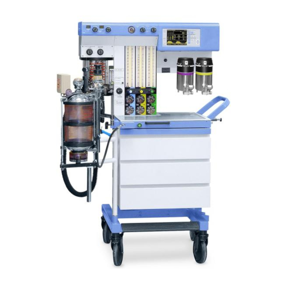
- Page 1 RETURN TO THIS MANUAL'S TABLE OF CONTENTS RETURN TO CD-ROM TABLE OF CONTENTS Setup and Installation Manual Part Number: 4113852-006 Rev: J Date: 25 February 2004 © 2004 Draeger Medical, Inc. Narkomed GS Anesthesia System...
- Page 2 RETURN TO THIS MANUAL'S TABLE OF CONTENTS RETURN TO CD-ROM TABLE OF CONTENTS...
-
Page 3: Table Of Contents
Moving the Narkomed GS ........ - Page 4 Connecting the Narkomed GS to Electrical Power ........
- Page 5 RETURN TO THIS MANUAL'S TABLE OF CONTENTS RETURN TO CD-ROM TABLE OF CONTENTS Introduction Section contents: Introduction ................1-2 Warnings ................1-2 Cautions ................1-2 Notes ................... 1-2 Draeger Medical, Inc. Narkomed GS Setup and Installation Manual...
-
Page 6: Introduction
RETURN TO CD-ROM TABLE OF CONTENTS Introduction Introduction This manual provides instructions for moving, setting up, testing, and maintaining a Narkomed GS anesthesia machine. • Moving the Machine—Section 2 shows how to move the machine safely. • Setup and Installation—The following sections explain how to set up and install the anesthesia machine. -
Page 7: Moving The Narkomed Gs
RETURN TO THIS MANUAL'S TABLE OF CONTENTS RETURN TO CD-ROM TABLE OF CONTENTS Moving the Narkomed GS Section contents: Getting the Machine Ready to Move ........2-2 Moving the Machine ............2-2 Draeger Medical, Inc. Narkomed GS Setup and Installation Manual... - Page 8 2. Using only the handle or push/pull bar shown in the illustration, move the machine. Do not push or pull the anesthesia machine using the absorber system, vaporizers, ventilator bellows, cord wrap, or boom arm. Narkomed GS Setup and Installation Manual Draeger Medical, Inc.
- Page 9 RETURN TO THIS MANUAL'S TABLE OF CONTENTS RETURN TO CD-ROM TABLE OF CONTENTS Moving the Narkomed GS HANDLE PUSH/PULL BAR (OPTIONAL) CASTER LOCKING LEVERS SU87026 Draeger Medical, Inc. Narkomed GS Setup and Installation Manual...
- Page 10 RETURN TO THIS MANUAL'S TABLE OF CONTENTS RETURN TO CD-ROM TABLE OF CONTENTS...
- Page 11 Installing the Patient Line Boom Arm ........ 3-22 Installing the Manual Sphygmomanometer Gauge.... 3-23 Installing the Second Shelf ..........3-25 Installing the Shelf Extender..........3-27 Installing the Outlet Strip ........... 3-29 Draeger Medical, Inc. Narkomed GS Setup and Installation Manual...
-
Page 12: Section 3. Setup And Installation
RETURN TO CD-ROM TABLE OF CONTENTS Setup and Installation Setup Following is a checklist for the initial setup of a Narkomed GS Anesthesia Checklist Machine. This setup must be performed by or under the direct supervision of an authorized representative of DrägerService. Items 1 through 16 are described in this section;... -
Page 13: Installing The Absorber Swivel Arm Stop Pin
Order (Fixed Vapor Left position: Halothane Mount System) Center position: Enflurane Right position: Isoflurane (or desflurane) NOTE: To install a TEC 6 desflurane vaporizer, see Service Procedure SP00091. Draeger Medical, Inc. Narkomed GS Setup and Installation Manual... - Page 14 Order” above), and tighten the screws. WARNING: Use only the screws from the plastic plates. 6. When all vaporizers are installed, test the exclusion system for proper operation. If adjustment is needed, refer to the Narkomed GS Service Manual. Reinstall the back cover. COVER SCREWS...
- Page 15 6. Test the interlock for proper operation. Verify that only one vaporizer at a time can be turned on. Return all vaporizers to their Zero position at completion of the test. Draeger Medical, Inc. Narkomed GS Setup and Installation Manual...
- Page 16 RETURN TO THIS MANUAL'S TABLE OF CONTENTS RETURN TO CD-ROM TABLE OF CONTENTS Setup and Installation LOCKING LEVER VAPORIZER MOUNTING MANIFOLD O-RINGS REMOVABLE VAPORIZER MOUNTING ARRANGEMENT (TOP VIEW) SU00114 SELECTOR LEVER Narkomed GS Setup and Installation Manual Draeger Medical, Inc.
-
Page 17: Filling The Vaporizer
Absorber presumes the use of an appropriate scavenger system. System WARNING:The Narkomed GS's patient breathing system must not be used in conjunction with any additional components that establish a flow direction. WARNING:Hoses and bags attached to the 22 mm hose terminals of the... - Page 18 SET SCREW (P/N HW10002) ABSORBER FRESHGAS LOCKING DEVICE ABSORBER W/15MM FEMALE MOUNTING FITTING STUD FRESHGAS HOSE W/15MM MALE FITTING Y-PIECE BREATHING BAG SWIVEL BAG MOUNT W/22MM BREATHING BAG TERMINAL ABSORBER POLE SU14718B Narkomed GS Setup and Installation Manual Draeger Medical, Inc.
- Page 19 19 mm terminal marked SCAVENGER HOSE on the scavenger. VENTILATOR BELLOWS PRESSURE W/22MM VENTILATOR SENSING PORT HOSE TERMINAL QUICK-CONNECT FITTING SU98101B OXYGEN VALVE SENSOR ULTRASONIC FLOW SENSOR VENTILATOR 22MM BREATHING HOSE 19MM SCAVENGER HOSE ABSORBER POLE TO SCAVENGER Draeger Medical, Inc. Narkomed GS Setup and Installation Manual...
-
Page 20: Installing The Breathing Pressure Pilot Line
REAR PANEL OF VENTILATOR BOX VOLUME OXYGEN BREATHING AUTO/BAG SENSOR SENSOR PRESSURE SELECTOR QUICK-CONNECT FITTINGS SHORT PILOT LINE (P/N 4109368) SU00603A ABSORBER TOP ASSEMBLY 3-10 Narkomed GS Setup and Installation Manual Draeger Medical, Inc. - Page 21 Y-piece. MALE LUER-LOCK FITTING LONG PLASTIC PILOT LINE HOSE CLIPS (P/N 4108528) VOLUME OXYGEN BREATHING AUTO/BAG SENSOR SENSOR PRESSURE SELECTOR QUICK-CONNECT FITTING REAR PANEL OF SU00604A VENTILATOR BOX Draeger Medical, Inc. Narkomed GS Setup and Installation Manual 3-11...
-
Page 22: Installing The Auto-Bag Sensor Cord
REAR PANEL OF VENTILATOR BOX SU00602 VOLUME OXYGEN BREATHING AUTO/BAG SENSOR SENSOR PRESSURE SELECTOR SENSOR CORD CONNECTOR INTERFACE CABLE MANUAL/ AUTOMATIC SELECTOR VALVE MANUAL/ AUTOMATIC SELECTOR SENSOR 3-12 Narkomed GS Setup and Installation Manual Draeger Medical, Inc. -
Page 23: Installing The Oxygen Sensor
3. Remove any protective covering from the sensor housing. 4. Perform an oxygen sensor calibration as described in “Operation - Oxygen Monitoring” in the Narkomed GS Operator's Manual . 5. Insert the sensor assembly into the inspiratory valve dome by pressing it into place. -
Page 24: Installing The Ultrasonic Flow Sensor
3. Connect the sensor plug to the VOLUME SENSOR interface on the rear panel of the ventilator box. ULTRASONIC FLOW SENSOR SENSOR CONNECTOR PLUG HOSE EXPIRATORY HOSE TERMINAL FLOW SENSOR BRACKET EXPIRATORY VALVE ABSORBER SU00009A ASSEMBLY 3-14 Narkomed GS Setup and Installation Manual Draeger Medical, Inc. -
Page 25: Installing The Bain Circuit Adapter
APL VALVE OXYGEN SENSOR 22MM M/15MM F EXPIRATION TERMINAL ABSORBER APL VALVE BAIN CIRCUIT ADAPTER BAIN CIRCUIT BAIN CIRCUIT HOSE BARB FOR FRESH GAS HOSE FRESH GAS BREATHING OUTLET SU14730A Draeger Medical, Inc. Narkomed GS Setup and Installation Manual 3-15... - Page 26 TERMINAL ON CIRCUIT VENTILATOR BELLOWS ASSEMBLY) SET SCREW BAIN CIRCUIT HOSE BARB FOR FRESH GAS HOSE MOUNTING STUD FRESH GAS COMMON OUTLET BREATHING BAG MOUNT FRESH GAS HOSE BREATHING BAG SU14719A 3-16 Narkomed GS Setup and Installation Manual Draeger Medical, Inc.
- Page 27 Bain Circuit Adapter marked EXPIRATION. 7. Connect the fresh gas hose between the fresh gas outlet on the Narkomed GS, and the hose barb fitting on the Bain Circuit (inner tube connection). 8. Set the APL valve fully open, set the PEEP valve (if supplied) at minimum, and set the Man/Auto selector to BAG.
- Page 28 SU20997 OUTLET OXYGEN SENSOR FRESH GAS LOCKING BAR (EXTENDED POSITION) 15MM MALE FITTING ADAPTER OXYGEN SENSOR PORT STEM FRESH GAS HOSE BARBED FITTING FOR NON-REBREATHING OXYGEN GAS CIRCUIT SENSOR PLUG 3-18 Narkomed GS Setup and Installation Manual Draeger Medical, Inc.
-
Page 29: Connecting The Open Reservoir Scavenger System
RETURN TO THIS MANUAL'S TABLE OF CONTENTS RETURN TO CD-ROM TABLE OF CONTENTS Setup and Installation Connecting The Open Reservoir Scavenger is installed on the Narkomed GS before the Open shipping. The scavenger hose connections are described below. Reservoir Scavenger... - Page 30 3. Connect a wall suction hose between the wall suction outlet and the suction terminal (DISS fitting or hose barb with adapter) on the scavenger. Connecting The Scavenger Interface for Passive Systems is installed on the Narkomed GS before shipping. The scavenger hose connections are Scavenger described below. Interface for Passive...
- Page 31 3. Connect another 19 mm scavenger hose between the 19 mm terminal labeled EXHAUST (on the bottom of the scavenger) and the hospital exhaust system grill adapter. Draeger Medical, Inc. Narkomed GS Setup and Installation Manual 3-21...
-
Page 32: Installing The Patient Line Boom Arm
FLAT HEAD SOCKET SCREW (2X) 1/4 - 20 X 3/4 IN. SOCKET HEAD CAP SCREW (2X) SUPPORT PLATE 1/4-20 X 7/8 IN. BUTTON SU87030 HEAD SOCKET SCREW AND LOCK WASHER (4X) 3-22 Narkomed GS Setup and Installation Manual Draeger Medical, Inc. - Page 33 Gauge 2. Screw the manual sphygmomanometer gauge mounting ring tightly (optional) onto the gauge mount, oriented with the gauge facing forward. GAUGE THREADED MOUNT MOUNTING RING MANUAL SPHYGMOMANOMETER GAUGE SU87032 Draeger Medical, Inc. Narkomed GS Setup and Installation Manual 3-23...
- Page 34 4. Connect the cuff extension hose to the BP CUFF fitting on the interface panel. Connect the other end of the cuff extension hose to a blood pressure cuff. Refer to the Narkomed GS Operator's Instruction Manual for selecting the correct size blood pressure cuff.
-
Page 35: Installing The Second Shelf
SHELF ASSEMBLY (4) 1" LG BUTTON HEAD CAP SCREW 3 1/2" 3 1/2" HEIGHT CONFIGURATION (4) 1" LG BUTTON HEAD CAP SCREW 6 1/4" SU87029 6 1/4" HEIGHT CONFIGURATION Draeger Medical, Inc. Narkomed GS Setup and Installation Manual 3-25... - Page 36 (4) FLAT (4) HEX HEAD SCREW WASHER (4) SPLIT LOCK WASHER 14 1/2" (4) ACORN NUT (2) EXTENDER BRACKET (4) 1" LG BUTTON HEAD CAP SCREW 14 1/2" HEIGHT CONFIGURATION SU87028 3-26 Narkomed GS Setup and Installation Manual Draeger Medical, Inc.
-
Page 37: Installing The Shelf Extender
10-32 x f in. socket head cap screws. If the machine is not equipped with a vapor box push/pull bar, install 10-32 x ½ in. button head screws at these four locations. Draeger Medical, Inc. Narkomed GS Setup and Installation Manual 3-27... - Page 38 5/16-24 X 5/8 SS BO (2)SCREW-BUTTON HD SKT 10-32 X 1/2 SS BO SHELF EXTENDER (4)SCREW-CAP SKT HD CLIP BOARD 10-32 X 7/8 SS HOOK PUSH/ PULL CONFIGURATION WITH PUSH/PULL BAR 3-28 Narkomed GS Setup and Installation Manual Draeger Medical, Inc.
-
Page 39: Installing The Outlet Strip
NOT connect the power cord to the convenience receptacles on the anesthesia machine. REAR VIEW OF ANESTHESIA MACHINE MOUNTING CLIP (2X) MOUNTING SCREW (2X) (P/N HW02014) WHEN USING THIS OUTLET STRIP..SU87031 OUTLET STRIP Draeger Medical, Inc. Narkomed GS Setup and Installation Manual 3-29... - Page 40 RETURN TO THIS MANUAL'S TABLE OF CONTENTS RETURN TO CD-ROM TABLE OF CONTENTS...
- Page 41 RETURN TO THIS MANUAL'S TABLE OF CONTENTS RETURN TO CD-ROM TABLE OF CONTENTS Gas Supply Connections Section contents: Gas Supply Connections ............. 4-2 Connecting the Cylinders ............ 4-3 Connecting the Pipelines............. 4-4 Draeger Medical, Inc. Narkomed GS Setup and Installation Manual...
- Page 42 Color codes for the USA, ISO, and Germany are shown in the following table. GAS SYSTEM COLOR CODING MARKING GERMANY Black/White Yellow Yellow Checkered Carbon Dioxide Gray Gray Black Nitrous Oxide Blue Blue Gray Oxygen Green White Blue Narkomed GS Setup and Installation Manual Draeger Medical, Inc.
- Page 43 RETURN TO THIS MANUAL'S TABLE OF CONTENTS RETURN TO CD-ROM TABLE OF CONTENTS Gas Supply Connections Connecting The Narkomed GS is equipped with ANSI standard pin-indexed hanger the Cylinders yokes for E-size gas cylinders. WARNING:Oil and grease may combine explosively with oxygen or nitrous oxide.
- Page 44 For further information regarding safety precautions in the use of medical gases, consult Compressed Gas Association pamphlet P-2 and appropriate sections of National Fire Protection Association Standard 99. Narkomed GS Setup and Installation Manual Draeger Medical, Inc.
- Page 45 2. Connect the other end of each supply hose to the appropriate functioning hospital pipeline outlet. 3. Check the pipeline pressure gauge on the front of the Narkomed GS for sufficient pipeline pressure (50-55 psi). NIST OPTION...
- Page 46 RETURN TO THIS MANUAL'S TABLE OF CONTENTS RETURN TO CD-ROM TABLE OF CONTENTS...
- Page 47 RETURN TO THIS MANUAL'S TABLE OF CONTENTS RETURN TO CD-ROM TABLE OF CONTENTS Power-up and System Configuration Section contents: Connecting the Narkomed GS to Electrical Power ....5-2 Power-Up Diagnostics Test..........5-3 Draeger Medical, Inc. Narkomed GS Setup and Installation Manual...
- Page 48 Connect the Narkomed GS to electrical power as follows: 1. Verify that the Narkomed GS's SYSTEM POWER switch is set to STANDBY. 2. Enable all circuit breakers by placing them in the "set" (pushed in) position.
- Page 49 RETURN TO THIS MANUAL'S TABLE OF CONTENTS RETURN TO CD-ROM TABLE OF CONTENTS Electrical Connections and Power-Up Power-Up 1. Power-Up Diagnostics TestTurn the Narkomed GS's System Power Diagnostics switch to ON. The self-diagnostic screen is displayed. A typical power- Test up diagnostic screen is shown in the illustration.
- Page 50 RETURN TO THIS MANUAL'S TABLE OF CONTENTS RETURN TO CD-ROM TABLE OF CONTENTS...
- Page 51 RETURN TO THIS MANUAL'S TABLE OF CONTENTS RETURN TO CD-ROM TABLE OF CONTENTS Testing and PMC NOTE: The following pages in this section comprise an excerpt from the PMC section of the corresponding service manual. Therefore any revision notices on these pages will reflect the revision level at which they occurred in the service manual, and are not related to the revision level of this setup and installation manual.
- Page 52 RETURN TO THIS MANUAL'S TABLE OF CONTENTS RETURN TO CD-ROM TABLE OF CONTENTS...
- Page 53 RETURN TO CD-ROM TABLE OF CONTENTS NMGS PMC PROCEDURE PMC PROCEDURE, NARKOMED GS The procedures in this section shall be performed in their entirety each time a component is removed, replaced, calibrated, adjusted and during all scheduled Periodic Manufacturer’s Certification (PMC) visits. A PMC Checklist form, P/N S010211 is available from Draeger Medical, Inc.
- Page 54 RETURN TO THIS MANUAL'S TABLE OF CONTENTS RETURN TO CD-ROM TABLE OF CONTENTS NMGS PMC PROCEDURE (continued) Materials Required (continued): -- Fresh Gas Leak Test Adapter (P/N 4115041 or equivalent) -- Volumeter/Fresh Gas Adapter (P/N 4115042) -- Test Terminal 2x (P/N 4104389 or equivalent) -- Breathing System Leak Test Device (P/N S010159 or equivalent) -- PDM/Suction Adapter (P/N 4115038) -- Scavenger Adapter (P/N 4108114)
- Page 55 RETURN TO THIS MANUAL'S TABLE OF CONTENTS RETURN TO CD-ROM TABLE OF CONTENTS PMC PROCEDURE (continued) NMGS 4114807 PRESSURE TEST ASSEMBLY , WITH ADAPTERS 4114830-002 4114830-001 4114830-004 4114830-003 SP15001 4114830-006 4114830-005...
- Page 56 RETURN TO THIS MANUAL'S TABLE OF CONTENTS RETURN TO CD-ROM TABLE OF CONTENTS NMGS PMC PROCEDURE (continued) Liter vol/min S000081 2212300 FLOW METER MINUTE TEST STAND VOLUMETER 4104389 TEST TERMINAL ADAPTER 8401892 SIEMENS TEST LUNG SP15002...
- Page 57 RETURN TO THIS MANUAL'S TABLE OF CONTENTS RETURN TO CD-ROM TABLE OF CONTENTS PMC PROCEDURE (continued) NMGS S010158 FRESH GAS OUTLET VOLUME TEST DEVICE 4115041 FRESH GAS LEAK TEST DEVICE S010159 BREATHING SYSTEM LEAK TEST DEVICE 4115042 VOLUMETER/ FRESH GAS HOSE ADAPTER SP15003...
- Page 58 RETURN TO THIS MANUAL'S TABLE OF CONTENTS RETURN TO CD-ROM TABLE OF CONTENTS NMGS PMC PROCEDURE (continued) 4115038 PDM TO PATIENT SUCTION ADAPTER 4116111-001 4108114 NIBP W/LUER SCAVENGER ADAPTER TEST ADAPTER 4110709 LUER (F) 1/8 MPT ADAPTER FOR TOP PORT ON CAPNOMED FLOW METER 4115043 PDM TO...
- Page 59 Periodic Manufacturer's Certification General Instructions The purpose of this manual is to provide detailed instructions for performing a Periodic Manufacturer’s Certification (PMC) inspection on a Narkomed GS Anesthesia machine. A PMC consists of a complete Periodic Manufacturer’s Service procedure and a certification level inspection based on Draeger Medical, Inc.
- Page 60 RETURN TO THIS MANUAL'S TABLE OF CONTENTS RETURN TO CD-ROM TABLE OF CONTENTS NMGS PMC PROCEDURE (continued) Roman Numerals I and II do not affect the certification level but rather are provided to give further instructions to the end user as follows: I = The system in its present configuration shall only be used with a CO2 monitor incorporating an apnea warning.
- Page 61 Use the PM Certification form for Narkomed 2B/ 2C/ GS Anesthesia Systems (P/N S010211). Completely fill in the header information. All Narkomed GS are equipped with Humphrey valves and do not require lubrication. Indicate so with a (H) next to the “Vent Valve Lube Due” line on the Periodic Manufacturer’s Certification form.
- Page 62 Based on the “EQUIPMENT CONDITION” inspect the machine for any “DMI RECOMMENDATIONS” that would apply. Use the Narkomed GS section of the “RECOMMENDATION GUIDELINES INDEX” (P/N S010250). Note all applicable DMI recommendations on the Executive Summary.
- Page 63 Turn the System Power switch to ON and verify the “ON” LED is lighted? 6.1.2 Verify all LED’s on the keypad and ventilator displays are lit if applicable. 6.1.3 Verify that the following is displayed on the alarm CRT: NARKOMED GS COPYRIGHT 1996, NAD, INC. VERSION X.XX NMGS POD SOFTWARE ID. XXXX FIRMWARE...
- Page 64 RETURN TO THIS MANUAL'S TABLE OF CONTENTS RETURN TO CD-ROM TABLE OF CONTENTS NMGS PMC PROCEDURE (continued) 6.2.1.4 Set the safety analyzer GROUND switch to NORMAL. Set the POLARITY switch to OFF. 6.2.1.5 Plug the machine’s AC power cord into the safety analyzer. 6.2.1.6 Apply the analyzer’s test lead to a cylinder yoke bolt.
- Page 65 RETURN TO THIS MANUAL'S TABLE OF CONTENTS RETURN TO CD-ROM TABLE OF CONTENTS PMC PROCEDURE (continued) NMGS 6.2.4 Convenience Receptacle and Auxiliary Outlet Strip NOTE: This test will check the convenience receptacle and the auxiliary strip outlets for fault conditions such as open ground, reverse polarity, open line and open neutral.
- Page 66 RETURN TO THIS MANUAL'S TABLE OF CONTENTS RETURN TO CD-ROM TABLE OF CONTENTS NMGS PMC PROCEDURE (continued) CALIBRATIONS - One Year Service Interval; Due Date _____ 6.5.1 To bring up the Oxygen Monitor Service Screen, press the Mon Cal key. 6.5.2 Remove the Oxygen sensor from the valve dome adapter, and remove the Oxygen sensor capsule from the Oxygen sensor housing.
- Page 67 RETURN TO THIS MANUAL'S TABLE OF CONTENTS RETURN TO CD-ROM TABLE OF CONTENTS PMC PROCEDURE (continued) NMGS 6.6.8.1 Remove the Ultrasonic Flow Sensor connector hose. 6.6.8.2 Is the connector hose, connector, and O-ring in good condition? ___ (Y) 6.6.8.3 Remove the expiratory valve. 6.6.8.4 Is the washer under the valve in good condition? ___ (Y) 6.6.8.5...
- Page 68 RETURN TO THIS MANUAL'S TABLE OF CONTENTS RETURN TO CD-ROM TABLE OF CONTENTS NMGS PMC PROCEDURE (continued) 6.6.13 Are there two (2) spring clips on the absorber rods? ___ (Y) 6.6.14 Inspect the following: canisters, canister gaskets, dust cup and O-ring, and soda lime.
- Page 69 RETURN TO THIS MANUAL'S TABLE OF CONTENTS RETURN TO CD-ROM TABLE OF CONTENTS PMC PROCEDURE (continued) NMGS 6.8.1.5 Attach a test terminal (P/N 4104389) to the Fresh Gas Leak Test Adapter (P/N 4115041) then attach the test terminal to the bag mount. 6.8.1.6 Apply 50 cm H O test pressure to the absorber system and...
- Page 70 RETURN TO THIS MANUAL'S TABLE OF CONTENTS RETURN TO CD-ROM TABLE OF CONTENTS NMGS PMC PROCEDURE (continued) 6.8.3.2 Disconnect the hose from the expiratory valve or expiratory hose terminal on the ultrasonic flow sensor, if applicable and attach it to the test volumeter adapter. 6.8.3.3 Close the APL valve.
- Page 71 RETURN TO THIS MANUAL'S TABLE OF CONTENTS RETURN TO CD-ROM TABLE OF CONTENTS PMC PROCEDURE (continued) NMGS 6.8.5.9 Remove all test equipment. 6.8.6 PEEP Valve w/Bypass - If applicable 6.8.6.1 Open the APL valve. 6.8.6.2 Interconnect the inspiratory valve and expiratory valve or expiratory port on the ultrasonic flow sensor, if applicable with a 22 mm hose (P/N 9995132).
- Page 72 RETURN TO THIS MANUAL'S TABLE OF CONTENTS RETURN TO CD-ROM TABLE OF CONTENTS NMGS PMC PROCEDURE (continued) 6.8.7.5 Disconnect the pressure pilot line from the Bain Circuit and replace it with a PDM To Monitor Adapter (P/N 4115041). 6.8.7.6 Connect a test gauge to the adapter. 6.8.7.7 Occlude the expiration port on the Bain Circuit.
- Page 73 RETURN TO THIS MANUAL'S TABLE OF CONTENTS RETURN TO CD-ROM TABLE OF CONTENTS PMC PROCEDURE (continued) NMGS 6.9.14 After 1 minute, is the O concentration 97 to 100%? ___ (Y) 6.10 FLOWMETERS CONCENTRATIONS 6.10.1 Oxygen Flowmeter 6.10.1.1 Is it possible to adjust the flow of Oxygen over the full range of the flowmeters? ___ (Y) 6.10.1.2 Set the Oxygen flow to 4 l/min.
- Page 74 RETURN TO THIS MANUAL'S TABLE OF CONTENTS RETURN TO CD-ROM TABLE OF CONTENTS NMGS PMC PROCEDURE (continued) 6.10.6 Air Flowmeter - If applicable 6.10.6.1 If not configured with an Air Cylinder yoke, attach the Air Pipeline hose. 6.10.6.2 Is it possible to adjust the flow of the Air over the full range of the flowmeter? ___ (Y) 6.10.6.3 Set the Air flow to 2 l/min.
- Page 75 RETURN TO THIS MANUAL'S TABLE OF CONTENTS RETURN TO CD-ROM TABLE OF CONTENTS PMC PROCEDURE (continued) NMGS 6.10.10.2 Increase the pressure to 50 cm H 6.10.10.3 After 10 seconds, is the pressure within 40 to 60 cm H ___ (Y) 6.10.10.4 Remove the test gauge and adapter.
- Page 76 RETURN TO THIS MANUAL'S TABLE OF CONTENTS RETURN TO CD-ROM TABLE OF CONTENTS NMGS PMC PROCEDURE (continued) 6.11.2 Air Regulator - If applicable NOTE: Minimum cylinder pressure for Air regulator test is 1000 psi. 6.11.2.1 Configure the test gauge (P/N 4114807) using an Air nut/ stem DISS connector (P/N 4114830-002) on the hose and a DISS body connector (P/N 4114830-001) on the valve body side.
- Page 77 RETURN TO THIS MANUAL'S TABLE OF CONTENTS RETURN TO CD-ROM TABLE OF CONTENTS PMC PROCEDURE (continued) NMGS 6.11.3 Regulator NOTE: Minimum cylinder pressure for O regulator test is 1000 psi. 6.11.3.1 Configure a test gauge (P/N 4114807) using an O nut/stem DISS connector (P/N 4114830-006) on the hose and an O DISS body connector (P/N 4114830-005) on the valve body...
- Page 78 RETURN TO THIS MANUAL'S TABLE OF CONTENTS RETURN TO CD-ROM TABLE OF CONTENTS NMGS PMC PROCEDURE (continued) 6.12.6 Remove the test equipment. 6.13 OXYGEN SUPPLY FAILURE PROTECTION 6.13.1 Connect all pipeline supplies. 6.13.2 Close the Oxygen flow control valve if applicable. 6.13.3 *Is the flow of Oxygen 150 to 200ml/min.? ___ (Y) 6.13.4...
- Page 79 RETURN TO THIS MANUAL'S TABLE OF CONTENTS RETURN TO CD-ROM TABLE OF CONTENTS PMC PROCEDURE (continued) NMGS 6.14.10 Increase the test pressure slowly. Does a VENT PRESS HI activate as a warning alarm within 47 to 53 cm H O? ___ (Y) 6.14.11 Create a sub-atmospheric test pressure slowly.
- Page 80 RETURN TO THIS MANUAL'S TABLE OF CONTENTS RETURN TO CD-ROM TABLE OF CONTENTS NMGS PMC PROCEDURE (continued) 6.15.18 Adjust the Inspiratory Flow until a peak pressure of 80 cm H O is achieved. 6.15.19 If applicable, set the Pressure Limit Control to within the 30 range. Readjust within the band as necessary to achieve proper value.
- Page 81 RETURN TO THIS MANUAL'S TABLE OF CONTENTS RETURN TO CD-ROM TABLE OF CONTENTS PMC PROCEDURE (continued) NMGS 6.16.2 Does the bellows remain fully inflated during the expiratory pause phase? ___ (Y) 6.16.3 Remove the ventilator hose from the VENTILATOR HOSE terminal. 6.16.4 Attach a test terminal to the bellows assembly ventilator hose terminal.
- Page 82 RETURN TO THIS MANUAL'S TABLE OF CONTENTS RETURN TO CD-ROM TABLE OF CONTENTS NMGS PMC PROCEDURE (continued) 6.17.6 Adjust the O flow to 3 l/min. 6.17.7 Is the tidal volume on the test volumeter greater than 250 ml? ___(Y) 6.17.8 Adjust the tidal volume to the 100 ml mark on the pediatric bellows assembly.
- Page 83 RETURN TO THIS MANUAL'S TABLE OF CONTENTS RETURN TO CD-ROM TABLE OF CONTENTS PMC PROCEDURE (continued) NMGS 6.18.9 Adjust the Oxygen flow to 10 l/min. 6.18.10 Is the PEEP displayed on the monitor within 0 to 3 cm H O? ___ (Y) 6.18.11 Close the Oxygen flow control valve.
- Page 84 RETURN TO THIS MANUAL'S TABLE OF CONTENTS RETURN TO CD-ROM TABLE OF CONTENTS NMGS PMC PROCEDURE (continued) Go to step 6.19.2.5. 6.19.1.4 Cleaning procedure for assemblies with many small vent ports. Remove the scavenger mounting screws. Remove the scavenger flow control needle valve assembly.
- Page 85 RETURN TO THIS MANUAL'S TABLE OF CONTENTS RETURN TO CD-ROM TABLE OF CONTENTS PMC PROCEDURE (continued) NMGS 6.19.2.12 What is the pressure on the test gauge? ___ cm H O (0 to -0.5) 6.19.2.13 Remove the test equipment, re-cap the scavenger adapter port or remove the scavenger adapter and reconnect the scavenger hose.
- Page 86 RETURN TO THIS MANUAL'S TABLE OF CONTENTS RETURN TO CD-ROM TABLE OF CONTENTS NMGS PMC PROCEDURE (continued) 6.20.2.7 Connect a test pressure monitor to the hose barb on the adapter using a PDM/Suction Adapter (P/N 4115038). 6.20.2.8 Remove the transfer hose from the bottom of the scavenger and occlude this port.
- Page 87 RETURN TO THIS MANUAL'S TABLE OF CONTENTS RETURN TO CD-ROM TABLE OF CONTENTS PMC PROCEDURE (continued) NMGS 6.21.1.10 Reinstall the valve in the housing, and then reinstall the housing into the scavenger body. NOTE: This valve does not require washers or O-rings. 6.21.1.11 Remove the valve housing on the right side of the scavenger body by turning it counter-clockwise.
- Page 88 RETURN TO THIS MANUAL'S TABLE OF CONTENTS RETURN TO CD-ROM TABLE OF CONTENTS NMGS PMC PROCEDURE (continued) 6.21.2.15 Remove the test equipment and reconnect the scavenger hose. 6.21.2.16 Close the Oxygen flow control valve. 6.22 SUCTION REGULATOR - 6-month Service Interval; Due Date _____, If applicable 6.22.1 Set the vacuum on/off valve to the ON position.
- Page 89 RETURN TO THIS MANUAL'S TABLE OF CONTENTS RETURN TO CD-ROM TABLE OF CONTENTS PMC PROCEDURE (continued) NMGS 6.24.5 Verify the APL valve knob is turned completely counterclockwise (fully open). 6.24.6 Place the AUTO/BAG selector in the BAG position. 6.24.7 Verify the ventilator hose is connected between the Auto/Man valve and Ventilator hose terminal.
- Page 90 RETURN TO THIS MANUAL'S TABLE OF CONTENTS RETURN TO CD-ROM TABLE OF CONTENTS...
- Page 91 RETURN TO THIS MANUAL'S TABLE OF CONTENTS RETURN TO CD-ROM TABLE OF CONTENTS...
- Page 92 RETURN TO THIS MANUAL'S TABLE OF CONTENTS RETURN TO CD-ROM TABLE OF CONTENTS Draeger Medical, Inc. 3135 Quarry Road Telford, PA 18969 Tel: (215) 721-5404 (800) 462-7566 Fax: (215) 721-9561 Web: www.draegermedical.com Printed in the U.S.A.
Need help?
Do you have a question about the Narkomed GS and is the answer not in the manual?
Questions and answers