Table of Contents
Advertisement
Quick Links
RTC 5
click
1. Introduction
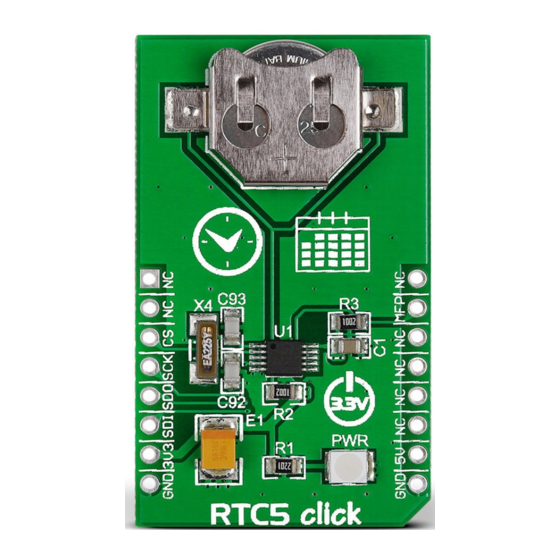
RTC5 click carries MCP79510, a real-
time clock/calendar with an SPI interface
(mikroBUS
MISO, MOSI, SCK and CS pins)
™
and a programmable interrupt for system
output. The clock frequency is derived
from an onboard 32.768KHz oscillator.
For backup power, RTC5 click has a coin-
cell Lithium polymer battery connector.
The board is designed to use a 3.3V power
supply only.
2. Soldering the headers
Before using your click board
™
, make sure
to solder 1x8 male headers to both left and
right side of the board. Two 1x8 male headers
are included with the board in the package.
2
Turn the board upside down so that
the bottom side is facing you upwards.
Place shorter pins of the header into the
appropriate soldering pads.
1
3
Turn the board upward again. Make sure
to align the headers so that they are
perpendicular to the board, then solder the
pins carefully.
3. Plugging the board in
Once you have soldered the headers your
board is ready to be placed into the desired
mikroBUS
socket. Make sure to align the cut
™
in the lower-right part of the board with the
markings on the silkscreen at the mikroBUS
socket. If all the pins are aligned
correctly, push the board all the
way into the socket.
4. Essential features
For storing data, the chip onboard RTC5 click
has 64-bytes of battery-backed SRAM and
1 kbit of EEPROM, along with 128 bits of
protected space for storing a unique ID. The
SPI interface has clock speeds of up to 5 MHz
which is enough for a millisecond alarm. The
clock/calendar automatically compensates
for leap years and months shorter than 31
days. The interrupt pin can be used to set up
alarms or events.
click
BOARD
™
www.mikroe.com
™
RTC 5 click Manual v100
0 1 0 0 0 0 0 0 8 5 7 6 9
Advertisement
Table of Contents

Related Manuals for mikroElektronika click BOARD RTC 5


Summary of Contents for mikroElektronika click BOARD RTC 5
- Page 1 2. Soldering the headers Before using your click board ™ , make sure to solder 1x8 male headers to both left and right side of the board. Two 1x8 male headers are included with the board in the package. RTC 5 click 4.
- Page 2 MISO +3.3V MOSI 9. Support BAT1 10uF 100nF MikroElektronika offers free tech support (www.mikroe.com/support) until the end of the product’s lifetime, so if something goes wrong, we’re ready and willing to help! 6. Dimensions 7. RTC5 click alternatives 10. Disclaimer ™...
Need help?
Do you have a question about the click BOARD RTC 5 and is the answer not in the manual?
Questions and answers