Advertisement
Quick Links
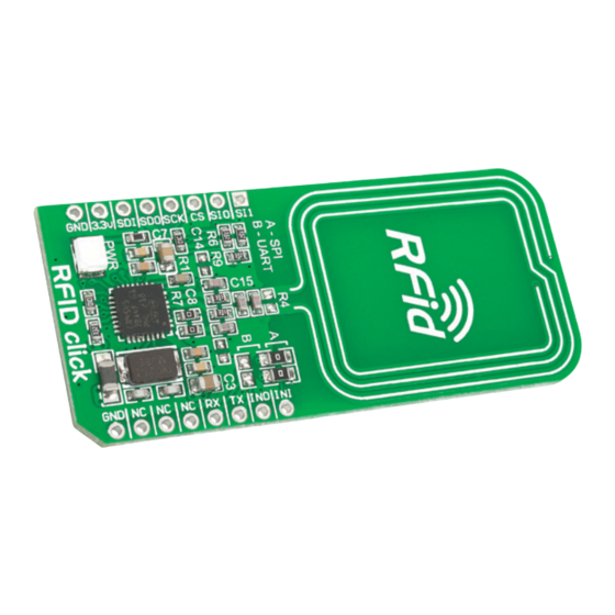
RFid
click
1. Introduction
RFid click
™
is an accessory board in
mikroBUS
form factor. It's a compact and
™
easy solution for adding RFid to your design.
CR95HF
It features
13.56 MHz contactless
transceiver as well as trace antenna. RFid
click
communicates with the target board
™
mikroBUS
microcontroller via
UART (TX,
™
RX), SPI (MISO, MOSI, SCK, CS) INT, RST,
PWM and AN lines. The board is designed
to use 3.3V power supply only. LED diode
(GREEN) indicates the presence of power
supply.
Downloaded from
DatasheetLib.com
Before using your click
™
to solder 1x8 male headers to both left
and right side of the board. Two 1x8 male
headers are included with the board in
the package.
2
Turn the board upside down so that
bottom side is facing you upwards.
Place shorter pins of the header into the
appropriate soldering pads.
- datasheet search engine
2. Soldering the headers
board, make sure
3
Turn the board upward again. Make sure
to align the headers so that they are
perpendicular to the board, then solder the
pins carefully.
3. Plugging the board in
Once you have soldered the headers your
board is ready to be placed into desired
mikroBUS
socket. Make sure to align the
™
cut in the lower-right part of the board
with the markings on the silkscreen at
the mikroBUS
aligned correctly, push the board all
1
4. Essential features
RFid click
module with integrated transceiver for
contactless applications. The board contains
dedicated internal frame controller and analog
front end (AFE) for RF communications. It
supports ISO/IEC 14443 type A and B, ISO/IEC
15693 and ISO/IEC 18092 protocols (tags) as
well as the detection, reading and writing of
NFC forum type 1, 2, 3 and 4 tags.
socket. If all of the pins are
™
the way into the socket.
CR95HF
with its
IC is a RFid
™
click
BOARD
www.mikroe.com
RFid click Manual
ver. 1.00
0 100000 024140
Advertisement

Subscribe to Our Youtube Channel
Related Manuals for mikroElektronika RFid click MIKROE-1434


Summary of Contents for mikroElektronika RFid click MIKROE-1434
- Page 1 2. Soldering the headers Before using your click board, make sure ™ to solder 1x8 male headers to both left and right side of the board. Two 1x8 male headers are included with the board in the package. RFid click 4.
- Page 2 MikroElektronika assumes no responsibility or liability for any errors or inaccuracies that may appear in the present document. Specification and information contained in the present schematic are subject to change at any time without notice. Copyright © 2013 MikroElektronika. All rights reserved.
Need help?
Do you have a question about the RFid click MIKROE-1434 and is the answer not in the manual?
Questions and answers