Table of Contents

Related Manuals for mikroElektronika mikroProg


Summary of Contents for mikroElektronika mikroProg
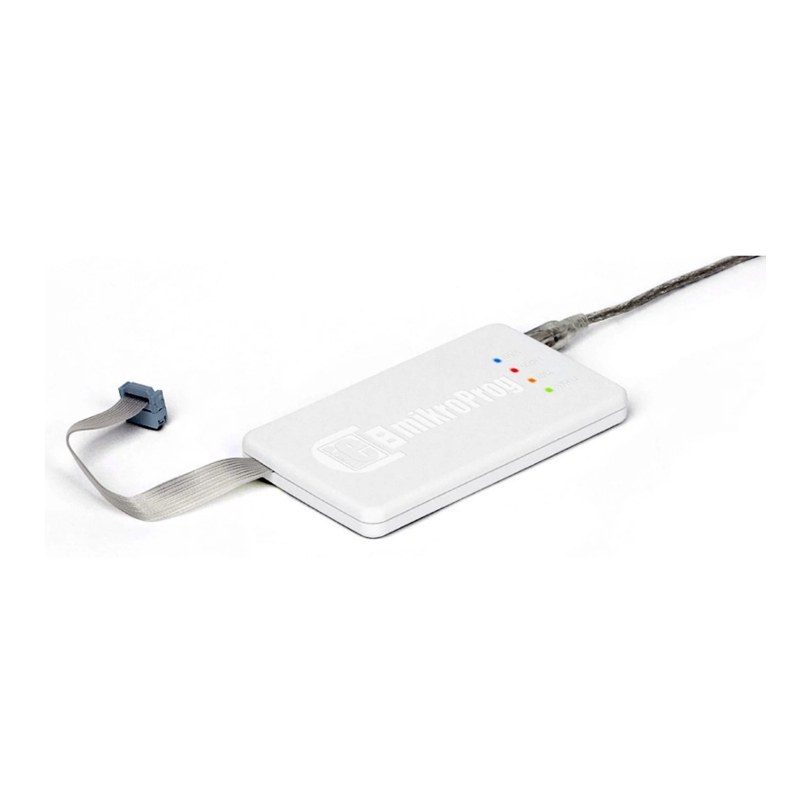
- Page 1 STM32 ® ™ mikroProg is a fast USB programmer with hardware debugger ™ support. Smart engineering allows mikroProg to support all ™ STM32® ARM® Cortex -M3 and Cortex -M4 microcontrollers ™ ™ in a single programmer.
- Page 2 TO OUR VALUED CUSTOMERS I want to express my thanks to you for being interested in our products and for having confidence in MikroElektronika. The primary aim of our company is to design and produce high quality electronic products and to constantly improve the performance thereof in order to better suit your needs.
-
Page 3: Table Of Contents
Introduction to mikroProg™ 4. Connecting with a target device Key features 5. Connector Pinout 1. Driver installation 6. mikroProg™ to 20-pin JTAG connector step 1 – Start installation 7. Connection schematics examples step 2 – Accept EULA 64-pin STM32® schematic step 3 –... -
Page 4: Introduction To Mikroprog
ARM® Cortex -M3 and Cortex -M4 devices in a single programmer! Outstanding performance, easy operation, elegant design and low ™ ™ price are it’s top features. It is supported in mikroElektronika, as well as in other ARM® compilers. Page 4... -
Page 5: Key Features
Key features Hardware Debugging - No need for firmware update - New microcontrollers supported via mikroProg Suite latest version of ™ for ARM® software What you see Flat cable USB MINIB connector DATA transfer indication LED ACTIVE indication LED LINK indication LED... -
Page 6: Driver Installation
20122011 www.mikroe.com DVD://download/eng/software/development-tools/arm/stm32/mikroprog/st_link_v2_usb_driver.zip Copyright ©2011 Mikroelektronika. All rights reserved. Mikroelektronika, Mikroelektronika logo and other Mikroelektronika trademarks are the property of Mikroelektronika. All other tradmarks are the property of their respective owners. Unauthorised copying, hiring, renting, public performance and broadcasting of this DVD prohibited. -
Page 7: Step 1 - Start Installation
step 1 – Start installation step 2 – Accept EULA In welcome screen click the Next> button Click Change button to select new destination folder or use the suggested installation path Click the Next> button Page 7... -
Page 8: Step 3 - Installing The Drivers
step 3 – Installing the drivers step 4 – Finish installation Finish Drivers are installed automatically Click the button to end installation process Page 8... -
Page 9: Connecting To A Pc
POWER LED should turn ON, indicating the presence of power supply. Amber-colored LINK LED will turn ON when link between mikroProg for STM32® ™ and PC is established. Link can be established only when correct drivers are installed on your PC. -
Page 10: Mikroprog Suite™ For Arm® Software
3. mikroProg Suite for ARM® software ™ mikroProg for STM32® programmer requires special programming software called mikroProg Suite ™ ™ for ARM®. This software is used for programming ALL of STM32® ARM® Cortex -M3 and Cortex ™ ™ microcontroller families. It features intuitive interface and SingleClick programming ™... - Page 11 Software installation wizard Start Installation Accept EULA and continue Install for All users or Current user Choose destination folder Installation in progress Finish installation Page 11...
-
Page 12: Connecting With A Target Device
IDC10 JTAG connector, as shown on Figure 4-1. In order to make For connection with a target device mikroProg ™ proper connection with the target board it is necessary to pay attention to IDC10 connector pinout. Every pin has a different purpose and for easy orientation IDC10 connector is marked with a little knob and incision between pins number 9 and 7, Figure 5-1. -
Page 13: Connector Pinout
5. Connector Pinout VCC-3.3V - Power supply - Ground - Ground TRST - JTAG reset - Ground TMS/SWDIO - JTAG Mode Select/SWD data I/O TCK/SWCLK - JTAG Clock/SWD clock - JTAG Data output - JTAG Data input #RESET - System Reset Figure 5-1: Female connector pinout Page 13... -
Page 14: Mikroprog™ To 20-Pin Jtag Connector
6. mikroProg to 20-pin JTAG connector ™ In order to connect mikroProg to 20-pin male JTAG connector it is necessary to use appropriate adapter, such as the mikroProg to ST-LINK V2 adaper, ™ Figure 6-1: Figure 6-1. This adapter should be first placed on 2x10 male connector. - Page 15 VCC-3.3V VCC-3.3V TRST VCC-3.3V RESET# TRST VCC-3.3V RESET# ST- Link V2 mikroProg ™ Figure 6-3: mikroProg™ to ST-Link V2 adapter connection schematics Page 15...
-
Page 16: Connection Schematics Examples
7. Connection schematics examples Following examples demonstrate connections with some of the most popular supported microcontrollers. Each one is carefully selected as a representative of the entire family. All MCUs use TMS, TCK, TDO, TDI, TRST, #RESET lines for JTAG programming or SWDIO, SWCLK for SWD (Serial Wire Debug) programming. These lines are located on same microcontroller pins within a family. -
Page 17: 64-Pin Stm32® Schematic
100K VCC- 3.3 PB12 PB13 PB14 PB15 VDDA GNDA 64pin TQFP 22pF 22pF STM32F10x STM32L15x NRST PA10 OSC_OUT VCC- 3.3 25MHz PA11 OSC_IN PA12 PC15/OSC32_OUT TMS/SWDIO PA13 PC14/OSC32_IN TCK/ SWCLK PC13 VBAT 32.768KHz TRST RESET# 22pF 22pF 100K Figure 7-1: Connection schematics for 64-pin STM32F10x/STM32L15x MCU via 2x5 male header Page 17... -
Page 18: 100-Pin Stm32® Schematic
100K VCC- 3.3 PB12 PB13 PB14 PA0-WKUP PB15 VDDA VREF+ VREF- PD10 GNDA PD11 PD12 22pF 22pF PD13 100pin TQFP PD14 PD15 NRST STM32F10x OSC_OUT 25MHz OSC_IN STM32L15x PC15/OSC32_OUT PC14/OSC32_IN PA10 PC13/TAMPER_RTC VCC- 3.3 PA11 VBAT 32.768KHz PA12 TMS/SWDIO PA13 TCK/ SWCLK 22pF... - Page 19 2.2uF VCC- 3.3 100K PB12 PB13 PB14 PA0-WKUP PB15 VDDA VREF+ GNDA PD10 PD11 PD12 22pF 22pF PD13 100pin TQFP PD14 PD15 NRST STM32F20x OSC_OUT 25MHz OSC_IN STM32F40x PC15/OSC32_OUT PC14/OSC32_IN PA10 PC13/TAMPER_RTC VCC- 3.3 2.2uF PA11 VBAT 32.768KHz PA12 TMS/SWDIO PA13 TCK/SWCLK 22pF...
-
Page 20: 144-Pin Stm32® Schematic
2.2uF VCC- 3.3 100K PB12 PB13 PB14 PB15 VDDA VREF+ GNDA PD10 PD11 PD12 22pF 22pF PD13 NRST PD14 OSC_OUT 25MHz PD15 OSC_IN PF10 144pin TQFP STM32F20x STM32F40x PC15/OSC32_OUT PC14/OSC32_IN PA10 PC13 VCC- 3.3 2.2uF PA11 VBAT 32.768KHz PA12 TMS/SWDIO PA13 TCK/ SWCLK... -
Page 21: 176-Pin Stm32® Schematic
2.2uF VCC- 3.3 100K PH12 PB12 PB13 PB14 VDDA PB15 VREF+ GNDA PD10 PD11 22pF 22pF PD12 PD13 NRST OSC_OUT 25MHz PD14 OSC_IN PD15 PF10 176pin TQFP STM32F20x STM32F40x PI11 PA10 PI10 VCC- 3.3 PA11 2.2uF PA12 PC15/OSC32_OUT TMS/SWDIO PA13 PC14/OSC32_IN TCK/SWCLK VCAP... - Page 22 Notes: Page 22...
- Page 23 No part of this manual, including product and software described herein, may be reproduced, stored in a retrieval system, translated or transmitted in any form or by any means, without the prior written permission of MikroElektronika. The manual PDF edition can be printed for private or local use, but not for distribution.
- Page 24 If you are experiencing some problems with any of our products or just need additional information, please place your ticket at www.mikroe.com/esupport If you have any questions, comments or business proposals, mikroProg for STM32 Manual ® ver. 1.00 do not hesitate to contact us at office@mikroe.com...
Need help?
Do you have a question about the mikroProg and is the answer not in the manual?
Questions and answers