Table of Contents

Related Manuals for mikroElektronika mikromedia 7


Summary of Contents for mikroElektronika mikromedia 7
- Page 1 7 for STM32F4 Amazingly compact, all-on-single-pcb development board carring 7” TFT Touch Screen and lots of multimedia peripherals, all driven by powerful STM32F407ZG microcontroller from Cortex -M4 family ® ™...
- Page 2 To our valued customers I want to express my thanks to you for being interested in our products and for having confidence in MikroElektronika. The primary aim of our company is to design and produce high quality electronic products and to constantly improve the performance thereof in order to better suit your needs.
-
Page 3: Table Of Contents
Table of Contents Introduction to mikromedia 7 for STM32F4 8. Audio Module System Specification 9. USB DEVICE connection Package Contains 10. USB HOST connection 1. Power supply 11. Accelerometer 2. STM32F407ZG microcontroller 12. Flash Memory Key microcontroller features 13. RF transceiver 3. -
Page 4: Introduction To Mikromedia 7 For Stm32F4
Introduction to mikromedia 7 for STM32F4 System Specification The mikromedia 7 for STM32F4 is a compact development power supply system with lots of on-board peripherals which allow Via USB cable (5V DC) or via connector development of devices with multimedia contents. The central... -
Page 5: Package Contains
Package Contains Damage resistant protective box Development board Roll USB and ethernet cables and headers User’s guide Schematic Distancers, plastic pen and microSD card Page 5... -
Page 6: Power Supply
The mikromedia 7 for STM32F4 board can be powered in four different ways: via two USB connectors using MINI-B USB cable provided with the board (CN4 or CN11), via battery connector using Li-Polymer battery (CN5) or via adapter connector using adapter power supply (CN3). - Page 7 VCC-3.3V VCC-5V VCC-3.3V VCC-3.3V USB-VBUS_ER VBUS_ER USB-PSW USB-CONN USB-VBUS VBUS USB-ID USB-VBUS_ER DC-VBUS# DC-VBUS# PDTC114EU 1.5uH Vusb_OUT TPS2041B C138 100nF VOUT VCC-5V 10uF PWR-EN PGND 100K PJ-002AH-SMT VAUX TPS63060 C139 C140 C141 VCC-PROG USB-PSW 22uF 10pF 22uF 22uF 22uF 100nF 10nF 100pF PMEG3010ER...
-
Page 8: Stm32F407Zg Microcontroller
2. STM32F407ZG microcontroller The mikromedia 7 for STM32F4 development board comes with 144-pin ARM® Cortex™-M4 STM32F407ZG microcontroller. This high-performance 32-bit microcontroller with its integrated modules and in combination with other onboard modules is ideal for multimedia applications. Key microcontroller features - Up to 210 DMIPS Operation (168MHz);... -
Page 9: Programming The Microcontroller
3. Programming the microcontroller Figure 3-1: STM32F407ZG Cortex ® ™ Microcontroller The microcontroller can be programmed in two ways: Using onboard mikroProg for STM32 programmer ™ Using external programmers for STM32 (like ST-LINK) Page 9... -
Page 10: Using Mikroprog™ Programmer
Using mikroProg™ programmer Figure 3-9: Figure 3-10: On-board mikroProg programmer mikroProg JTAG connector ™ ™ The microcontroller can be programmed with onboard to Figure 3-9. Signalization LED (LINK) is also provided on the mikroProg for STM programmer and mikroProg Suite opposite side of the PROG USB connector. - Page 11 VCC -3.3V Vbat_m cu VCC -3.3V R86 100K TMS-SWDI O BAT 1 TCK-SWCLK 3000T R C107 2.2uF RESET # JTAG VD D VCAP2 TMS-SWDI O PA13 OSC32_I N PA12 O SC32_OU T VBAT PA11 PC13 PA10 OSC32_I N PC14 32.768KHz O SC32_OU T VCC -3.3V VCC -3.3V...
-
Page 12: Mikroprog Suite™ For Arm® Software
mikroProg Suite™ for ARM® software mikroProg for STM32 programmer requires special programming software called ™ mikroProg Suite for ARM®. This software is used for programming ALL of STM32 ARM® ™ Cortex-M3 and Cortex-M4 microcontroller families. It features intuitive interface and ™... -
Page 13: Software Installation Wizard
Software installation wizard 1. Start Installation 2. Accept EULA and continue 3. Install for all users 4. Choose destination folder 5. Installation in progress 6. Finish installation Page 13... -
Page 14: Rtc Battery And Reset Button
4. RTC Battery and Reset Button RTC Battery mikromedia 7 for STM32F4 features an RTC battery holder for microcontroller RTC module. Battery is used as alternate source of power, so the RTC module can continue to keep time while the primacy source of power is off or currently unavailable. - Page 15 VCC -3.3V VCC -3.3V Vbat_m cu R86 100K BAT 1 3000T R C107 2.2uF VCC -3.3V VD D VCC -3.3V VCAP2 RESET # PA13 PA12 VBAT PA11 PC13 PA10 RESET PC14 100nF PC15 VCC -3.3V VCC -3.3V VD D STM32F407ZG VD D HDR 2 RESET #...
-
Page 16: Crystal Oscillators And 2.048V Reference
5. Crystal oscillators and 2.048V reference The board is equipped with 25MHz crystal oscillator (X5) circuit that provides external clock waveform to the microcontroller OSCO and OSCI pins. This base frequency is suitable for further clock multipliers and ideal for generation of necessary USB clock, which ensures proper operation of bootloader and your custom Figure 5-1:... - Page 17 VCC -3.3V VCC -3.3V Vbat_m cu R86 100K BAT 1 3000T R C107 2.2uF VD D VCC -3.3V VCAP2 PA13 PA12 VBAT PA11 PC13 PA10 OSC32_I N PC14 O SC32_OU T PC15 32.768KHz C108 C109 10pF 10pF VD D VCC -3.3V STM32F407ZG VD D PF10...
-
Page 18: Microsd Card Slot
6. microSD Card Slot Board contains microSD card slot for using microSD cards in your projects. It enables you to store large amounts of data externally, thus saving microcontroller memory. microSD cards use Serial Peripheral Interface (SPI) for communication with the microcontroller. - Page 19 VCC-MMC SD-DAT 2 DAT 2 SD-DAT 3 VCC -3.3V DAT 3 SD-CMD Vbat_m cu +3.3 V SD-CLK R86 100K GN D BAT 1 SD-DAT 0 DAT 0 3000T R SD-DAT 1 DAT 1 C107 SD-CD# 2.2uF VD D VCAP2 PA13 PA12 VCC -3.3V VBAT...
-
Page 20: Touch Screen
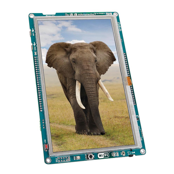
7. Touch Screen The development system features a 7‘‘ TFT 800x480 display covered with a resistive touch panel. Together they form a functional unit called a touch screen, (Figure 7-1). It enables data to be entered and displayed at the same time. The TFT display is capable of showing graphics in 262K diffe rent colors. - Page 21 TFT 1 FRD070IF40-A-T VCC -3.3V VCC -1.2V VCC -3.3V Vbat_m cu R86 100K BAT 1 3000T R C107 2.2uF VD D OSC32_I N O SC32_OU T VDD D VCAP2 VDDI O PA13 32.768KHz PA12 VDDI O VDD D VBAT PA11 C108 C109 PC13...
-
Page 22: Audio Module
8. Audio Module Figure 8-1: On-board VS1053 MP3 codec mikromedia 7 for STM32F4 features stereo audio codec VS1053. This module enables audio reproduction and sound recording by using stereo headphones with microphone connected to the system via a 3.5mm by the microcontroller over Serial Peripheral Interface (SPI). - Page 23 LINE- OU T_ L 10uF 3.3nF 100K VCC -3.3V VCC -1.8V VCC -3.3V Vbat_m cu LINE- O UT_ R C132 R86 100K 10uF 10uF 100nF 100nF 100nF 100nF 100nF 100nF 100nF 100nF 100nF 100nF BAT 1 3.3nF 100K 3000T R C107 2.2uF R17 1K...
-
Page 24: Usb Device Connection
9. USB DEVICE connection Cortex STM32F407ZG ® ™ microcontroller has integrated USB module, which enables you to implement USB communication functionality to your mikromedia board. Connection with target Figure 9-1: USB host is establish over MINI-B USB Connecting USB cable to connector. - Page 25 Vusb_IN VBUS R145 I/O1 I/O1 USB-D_N VCC -3.3V VBUS USB-D_P VCC -3.3V Vbat_m cu I/O2 I/O2 USB-ID R146 USBLC6-2SC6 R86 100K BAT 1 USB MINIB 3000T R USB-VBUS C107 2.2uF R132 C167 3.3nF ESDA5V3L VD D USB-GND VCC -3.3V VCAP2 PA13 USB-D_ P PA12...
-
Page 26: Usb Host Connection
10. USB HOST connection mikromedia 7 for STM32F4 can also Figure 10-1: be used as USB HOST which enables Connecting USB microcontroller to establish a connection cable to MINI-B USB with the target device (eg. USB keyboard, connector via USB USB mouse, etc). - Page 27 VCC -3.3V VCC -3.3V VCC-5V VCC -3.3V VCC -3.3V USB-VBUS_E R Vbat_m cu GN D R86 100K OU T Vusb_OU T BAT 1 VCC -3.3V 3000T R TPS2041B C107 C138 2.2uF 10uF 100nF PMEG3010ER VD D VCAP2 PA13 USB-PSW USB-D_ P PA12 USB-D_ N Vusb_IN...
-
Page 28: Accelerometer
11. Accelerometer Onboard ADXL345 accelerometer is used Figure 11-1: to measure acceleration in three axis: x, Accelerometer y and z. The accelerometer function is module defined by the user in the program loaded into the microcontroller. Communication between the accelerometer and the microcontroller is performed via the I interface. - Page 29 VCC -3.3V VCC -3.3V I 2C1_SCL VCC -3.3V I 2C1_SDA VCC -3.3V ACCEL-ADR GN D AD D Vbat_m cu VCC -3.3V GN D R86 100K GN D INT 2 ACCEL -I NT BAT 1 INT 1 3000T R I 2C1_SCL ADXL34 5 I 2C1_SDA C107...
-
Page 30: Flash Memory
12. Flash Memory Since multimedia applications are getting increasingly demanding, it is Figure 12-1: necessary to provide additional memory Flash memory space to be used for storing more data. module The flash memory module enables the microcontroller to use additional 8Mbit flash memory. - Page 31 VCC -3.3V Vbat_m cu VCC -3.3V VCC -3.3V R86 100K BAT 1 C128 3000T R 100nF C107 2.2uF SF_CS SPI2_MISO HOLD SPI2_SCK VD D R100 27 SPI2_MOSI GN D VCAP2 EN25F80 PA13 PA12 VBAT PA11 PC13 PA10 OSC32_I N PC14 O SC32_OU T PC15 VCC -3.3V...
-
Page 32: Rf Transceiver
13. RF Transceiver mikromedia 7 for STM32F4 board features RF transceiver chip with via the Serial Peripheral Interface (SPI). This RF transceiver module 2.4GHz chip antenna. It is suitable for wireless operation in the world is widely used for wireless PC peripherals, remote controllers, wide ISM frequency band at 2.400 - 2.4835 GHz with air data rate up... - Page 33 VCC -3.3V OSC32_I N O SC32_OU T VCC -3.3V Vbat_m cu 32.768KHz C109 C108 R86 100K 10pF 10pF BAT 1 3000T R C107 O SC_ I N VCC -3.3V 2.2uF OSC_OU T VD D 25MHz VCAP2 C111 C110 PA13 22pF 22pF PA12 VBAT...
-
Page 34: Wi-Fi
14. Wi-Fi mikromedia 7 for STM32F4 is equipped with SPWF01SA, a WiFi the main microcontroller on the mikromedia. Full featured TCP/ module with an integrated antenna from STMicroelectronics. The IP protocol stacks are also integrated. A BOOT jumper (zero ohm module packs a 2.4 GHz IEEE 802.11 b/g/n transceiver and its... - Page 35 VCC-3.3V VCC-3.3V VCC-3.3V VCC-3.3V PADS SPWF01SA R141 HDR-GPIO1 C158 HDR-GPIO1 HDR-GPIO2 HDR-GPIO2 100nF BOOT 10uF VCC -3.3V Vbat_m cu GPIO7 GPIO12 GPIO14 GPIO11 R86 100K WiFi-RTS GPIO13 RTS1_DP BAT 1 WiFi-CTS GPIO0 CTS1_DN 3000T R WiFi-RX GPIO1 RXD1 C107 GPIO4 GPIO9 R144 2.2uF...
-
Page 36: Ethernet Transceiver
15. Ethernet transceiver Figure 15-1: Ethernet Figure 15-2: transceiver module Ethernet RJ-45 (LAN8720A) connector The development board features an Ethernet transceiver module LAN8720A. It is ideal for local area networking (LAN). If you want to frames. Each frame contains source and destination addresses establish connection with a computer, router or other devices, the and error-checking data so that damaged data can be detected development board also contains a standard RJ-45 connector. - Page 37 VCC -3.3V C135 12K1 VCC -3.3V 100nF VCC -3.3V Vbat_m cu R86 100K LINK LAN-TX D1 BAT 1 TX D1 VDD 2A LAN-LED 2 LAN-TX D0 3000T R LED 2 TX D0 LAN-LED 1 LAN-T XEN C107 LED 1 TXE N LAN8720A LAN-RST # 2.2uF...
-
Page 38: Can Communication
Figure 16-2: and medical equipment. mikromedia 7 for STM32F4 is CAN transceiver with Node equipped with SN65HVD230 – a 3.3V CAN transceiver and TERMINATION jumper... - Page 39 VCC-3.3V PADS CN14 HDR-GPIO3 HDR-GPIO3 3.3V HDR-GPIO4 HDR-GPIO4 VCC -3.3V Vbat_m cu VCC-3.3V R86 100K BAT 1 CAN_TX 3000T R CANH C107 CANH CANL 2.2uF CANL CAN_RX Vref SN65HVD230 VD D 100nF VCAP2 PA13 PA12 VBAT PA11 PC13 PA10 TERMINATION R106 OSC32_I N CANL...
-
Page 40: Buzzer
17. Buzzer The board is also equipped with a piezo buzzer. It is an electric by generating a PWM signal. Frequency of the signal determines component which can be used to create sound waves when the pitch of the sound and duty cycle of the signal can be used to provided with electrical signal. - Page 41 VCC-5V VCC -3.3V Vbat_m cu BUZZE R R86 100K BAT 1 3000T R C107 PDT C114EU 2.2uF BUZZE R VD D VCAP2 PA13 PA12 VBAT PA11 PC13 PA10 OSC32_I N OSC32_I N PC14 O SC32_OU T O SC32_OU T PC15 32.768KHz C108 C109...
-
Page 42: Other Modules
IR receiver is used for infrared remote microcontroller analog pin. Temperature measurement range of control systems. The demodulated output signal obtained from IR mikromedia 7 for STM32F4 board is from -20°C to 70°C. Page 42... - Page 43 27K4 100K VCC-5V VCC -3.3V U17A LM358 AN-PD 150K VCC -3.3V PDT C114EU Vbat_m cu U17B LM358 C149 LED_R PD15 R86 100K 100nF BAT 1 3000T R C107 2.2uF VCC -3.3V VCC -3.3V C103 VD D 100nF VCC-5V VCAP2 PA13 PA12 VBAT PA11...
-
Page 44: Pads
5V pwr. Interrupt UART Analog lines Many microcontroller pins are available for further connectivity via two 1x26 rows of connection pads on both sides of the board. They are designed to match with mikromedia 7 SHIELD for STM32F4. Page 44... - Page 45 VCC -3.3V VCC -3.3V VCC -3.3V Vbat_m cu R86 100K VCC-3.3V BAT 1 3000T R VCC-3.3V C107 VCC-5V 2.2uF HDR2 HDR1 HDR-RST# HD R-INT 2 VD D HD R-INT 3 HDR-AN0 HDR-LN_OUT_L HDR-GPIO 1 VCAP2 HDR-LN_OUT_R HD R-PWM4 HDR-AN1 PA13 HDR-LN_IN_L HD R-PWM5 HDR-AN2...
-
Page 46: What's Next
® through each and every feature of suits you best on our website: to start writing your first projects. Visual mikromedia 7 for STM32F4 board. TFT software enables you to quickly create www.mikroe.com/arm/compilers You got to know its modules and your GUI. - Page 47 (including damages for loss of business profits and business information, business interruption or any other pecuniary loss) arising out of the use of this manual or product, even if MikroElektronika has been advised of the possibility of such damages.
- Page 48 ∫ If you have any questions, comments or business proposals, do not hesitate to contact us at office@mikroe.com mikromedia 7 for STM32F4 manual ver 1.02a Designed by MikroElektronika Ltd.
- Page 49 Mouser Electronics Authorized Distributor Click to View Pricing, Inventory, Delivery & Lifecycle Information: MikroElektronika MIKROE-1841...
Need help?
Do you have a question about the mikromedia 7 and is the answer not in the manual?
Questions and answers