
Related Manuals for mikroElektronika RS485


Summary of Contents for mikroElektronika RS485
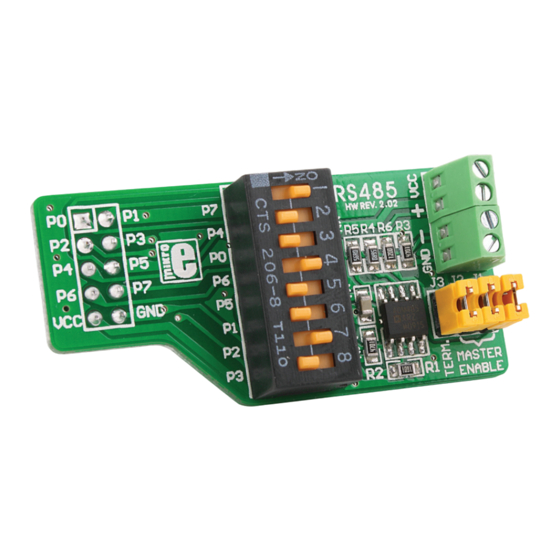
- Page 1 RS485 Expand development system capabilities by adding RS485 communication accessory board...
-
Page 2: To Our Valued Customers
TO OUR VALUED CUSTOMERS I want to express my thanks to you for being interested in our products and for having confidence in Mikroelektronika. The primary aim of our company is to design and produce high quality electronic products and to constantly improve the performance thereof in order to better suit your needs. - Page 3 Table of Contents Introduction to RS485 Key features System Specification 1. Connecting with development system 2. DIP switch settings 3. Connecting RS485 with other RS485 devices 4. Jumper settings 5. Schematic 6. Dimensions Page 3...
-
Page 4: Key Features
Accessory board is designed for usage with various development systems and other MCU device with 2x5 header. RS485 additional board is designed for RS485 communication which is suitable for usage in electrically noisy environment on long distances (up to 1200m (4000ft)). -
Page 5: System Specification
System Specification power supply 5V DC power consumption ~2mA outputs enabled board dimensions 50.42 x 23.88mm (1.99 x 0.94“) weight ~9g (0.02 lbs) Page 5... - Page 6 Figure 1-2: Connecting RS485 RS485 is designed for connection with 2x5 male headers on development system port’s via 2x5 female header on accessory board. Every pin on 2x5 female header is marked so for proper orientation just compare marks between accessory board and development system.
- Page 7 In order to connect RS485 to different development system it is necessary to make settings on DIP switch SW1. Every pin on DIP switch SW1 is connected to different pin of 2x5 female header. In table 1 is given list...
- Page 8 Figure 3-1: RS485 connected with other device via wire In order to connect RS485 accessory board with other RS485 devices on a network it is necessary to provide twisted wires or shielded cable which is good choice if Figure 3-2: RS485 screw cable goes thru electrically noisy environment.
- Page 9 RS485 accessory board it is necessary to set jumpers in appropriate position. - To set accessory board to first node in RS485 network place jumpers J1, J2 and J3 (Master and Term. jumpers are placed); - If accessory board is somewhere between first and last node remove all jumpers (Master and Term.
- Page 10 VCC-MCU VCC-MCU VCC-MCU 100nF R/T-P2 R/T-P3 R/T-P2 R/T-P3 ADM485 VCC-MCU Figure 5-1: Connection schematic Page 10...
- Page 11 50.42mm(1.99'’) 7.51mm(0.30'’) Figure 6-1: Dimensions Page 11...
- Page 12 Notes: Page 12...
- Page 13 Notes: Page 13...
- Page 14 Notes: Page 14...
- Page 15 No part of this manual, including product and software described herein, may be reproduced, stored in a retrieval system, translated or transmitted in any form or by any means, without the prior written permission of MikroElektronika. The manual PDF edition can be printed for private or local use, but not for distribution.
- Page 16 RS485 v2.02 If you want to learn more about our products, please visit our website at www.mikroe.com If you are experiencing some problems with any of our products or just need additional information, please place your ticket at www.mikroe.com/en/support If you have any questions, comments or business proposals, do not hesitate to contact us at office@mikroe.com...
- Page 17 Mouser Electronics Authorized Distributor Click to View Pricing, Inventory, Delivery & Lifecycle Information: MikroElektronika MIKROE-66...
Need help?
Do you have a question about the RS485 and is the answer not in the manual?
Questions and answers