Table of Contents
Advertisement
Advertisement
Table of Contents

Subscribe to Our Youtube Channel
Related Manuals for mikroElektronika EasyPIC 6


Summary of Contents for mikroElektronika EasyPIC 6
-
Page 1: User Manual
® EasyPIC User manual A large number of useful peripherals, ready-to-use practical code examples and a broad set of add-on boards make MikroElektronika development systems fast and reliable tools that can satisfy the needs of experienced engineers and beginners alike. - Page 2 TO OUR VALUED CUSTOMERS MikroElektronika. It is our intention to provide you with the best quality products. Furthermore, we will continue to improve our performance to better suit your needs. Nebojsa Matic General Manager The Microchip ® name and logo, PIC ® and dsPIC ® are registered trademarks of Microchip Technology Incorporated in the U.S.A. and...
-
Page 3: Table Of Contents
12.0. LEDs..............................17 13.0. Push Buttons............................18 14.0. Keyboards............................19 15.0. 2x16 LCD Display..........................20 16.0. On-Board 2x16 LCD Display......................... 21 17.0. 128x64 Graphic LCD Display........................ 22 18.0. Touch Panel............................23 19.0. I/O Ports..............................24 20.0. Port Expander ............................26 MikroElektronika... -
Page 4: Introduction To Easypic6 Development System
DC connector (7V to 23V AC or 9V to 32V DC); or over a USB cable (5V DC) Power consumption: up to 40mA (depending on how many on-board modules are currently active) Size: 26,5 x 22cm (10,43 x 8,66inch) Weight: ~417g (0.919lbs) MikroElektronika... -
Page 5: Key Features
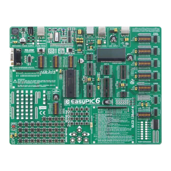
25. 36 LEDs to indicate pins’ logic state 10. DIP switches to enable pull-up/pull-down resistors 26. Alphanumeric LCD display contrast adjustment 11. Port pins’ pull-up/pull-down mode selection 27. Alphanumeric LCD display connector 12. I/O port connectors 28. RS-232 communication connector 13. PIC microcontroller sockets MikroElektronika... -
Page 6: Connecting The System To Your Pc
It is not possible to program PIC microcontrollers without having these devices installed. In case that you already have some of the MikroElektronika’s compilers installed on your PC, there is no need to reinstall the programmer as it will be automatically installed along with compiler installation. -
Page 7: Supported Microcontrollers
Figure 4. Only one microcontroller may be plugged into the development board at the same time. MikroElektronika... -
Page 8: On-Board Programmer
Write a code in some of PIC compilers, generate progress. care of loading data into the microcontroller. The principle of programmer’s operation For more information on the programmer refer to the relevant manual provided in the EasyPIC6 development system package. MikroElektronika... - Page 9 J7. When placed in the left-hand position, the MCLR pin has default function, i.e. is used as MCLR/Vpp. Otherwise, when the jumper is placed in the right-hand position, the MCLR pin is available The position of jumper J7 as an I/O pin. MikroElektronika...
-
Page 10: Mikroicd (Hardware In-Circuit Debugger)
The process of testing and debugging is performed by monitoring the state of all registers within the microcontroller ® while operating in real environment. The mikroICD software is integrated in all compilers designed by mikroElektronika (mikroBASIC ®... -
Page 11: Power Supply
0.22 on-board MOSFET 4x1N4007 programmer switch Top view AC/DC DRVC 220uH VCC-5V VCC-USB LD42 330uF POWER CMPR CN16 MC34063A 10uF 330uF 220pF MBRS140T3 Side view Side view Bottom view Side view Side view Figure 5-2: Power supply source schematic MikroElektronika... -
Page 12: Rs-232 Communication Interface
Figure 6-2 shows the microcontroller in DIP40 package (PIC16F887). MCLR OSC1 SUB-D 9p OSC2 MAX202 Bottom view DIP40 Figure 6-2: RS-232 module schematic Make sure that your microcontroller is provided with the USART module as it is not necessarily integrated in all microcontrollers. MikroElektronika... -
Page 13: Ps/2 Communication Interface
MICROCHIP. Jumpers J8 and J9 are placed in the same way as when using the programmer with mikroICD designed by MikroEektronika. CLK-PIC ICD connector DATA-PIC MCLR Side view Bottom view Front view RJ12 Figure 8-1: ICD connector ICD connector pinout and pin labels *ICD2 and ICD3 are registered trademarks of MICROCHIP® MikroElektronika... -
Page 14: Usb Communication
Bottom view OSC2 8MHz Bottom view 22pF 22pF DIP28 RC3/VUSB 22pF 22pF USB B DIP40 USB B LD44 LD44 USB ON USB ON 100nF 100nF 100nF 100nF Figure 9-3: PIC18F4550 USB communication schematic Figure 9-4: PIC18F2550 USB communication schematic MikroElektronika... -
Page 15: Ds1820 Temperature Sensor
RA5 pin) the RE2 pin) Jumper J11 in the upper position MCLR VCC-MCU DS1820 VCC-MCU VCC-MCU VCC-MCU OSC1 OSC2 Botoom view 8MHz VCC-MCU 22pF 22pF DIP40 Figure 10-5: 1-wire communication schematic MikroElektronika... -
Page 16: A/D Converter
Figure 11-5: Microcontroller in DIP28 package and A/D converter test inputs connectiion inputs connection In order to enable the microcontroller to accurately perform A/D conversion, it is necessary to turn off LED diodes and pull-up/pull-down resistors on port pins used by the A/D converter. MikroElektronika... -
Page 17: Leds
(1) is present on the pin. In order to enable LEDs, it is necessary to select appropriate port PORTA/E, PORTB, PORTC or PORTD using the DIP switch SW9. Notch indicating the SMD LED cathode R=U/I SMD LED Microcontroller SMD resistor limiting current Figure 12-1: LEDs Figure 12-2: LED diode and PORTB connection schematic MikroElektronika... -
Page 18: Push Buttons
By pressing any push button (R0-R7) when jumper J17 is in the VCC-MCU position, a logic one (5V) will be applied to the appropriate microcontroller pin as shown in Figure 13-2. Jumper J17 in the pull-up position Figure 13-2: PORTB push button connection schematic MikroElektronika... -
Page 19: Keyboards
8x10K RD2 and RD3 are connected BAT43 220R to pull-down Side view resistors through DIP switch SW4 VCC- VCC-MCU 220R OSC1 OSC2 220R 8MHz 220R 22pF 22pF 220R DIP40 Figure 14-4: Keypads (4x4 and MENU) and microcontroller connection schematic MikroElektronika... -
Page 20: 2X16 Lcd Display
4-bit mode. Alphanumeric digits are displayed in two lines each containing up to 16 characters of 7x5 pixels. Connector for alphanumeric LCD display Contrast adjustment potentiometer Figure 15-1: Alphanumeric LCD connector Figure 15-2: 2x16 LCD display VCC-MCU MCLR Top view LCD-GLCD BACKLIGHT VCC-MCU VCC-MCU VCC-MCU OSC1 OSC2 8MHz 22pF 22pF DIP40 2x16 LCD display connection schematic MikroElektronika... -
Page 21: On-Board 2X16 Lcd Display
VCC-MCU GPB7 GPA0 VCC- PE-INTA INTA OSC1 PE-INTB INTB OSC2 RESET PE-CS# VCC-MCU 8MHz SPI- SPI-SCK SPI- MOSI SPI-MISO SPI- MISO SPI-MOSI SW10 MCP23S17 100K 22pF 22pF VCC-MCU DIP40 Top view Figure 16-2: On-board 2x16 LCD display connection schematic MikroElektronika... -
Page 22: 128X64 Graphic Lcd Display
Potentiometer P3 is used for the GLCD display contrast adjustment. Switch 8 on the DIP switch SW6 is used for turning on/off display backlight. Contrast adjustment potentiometer GLCD connector Touch panel connector Figure 17-1: GLCD display Figure 17-2: GLCD connector MCLR LCD-GLCD Top view BACKLIGHT OSC1 OSC2 22pF DIP40 Figure 17-3: GLCD display connection schematic MikroElektronika... -
Page 23: Touch Panel
Now you can plug a GLCD display into the appropriate connector as shown in Figure 4. LEDs and pull-up/pull-down resistors on the RA0 and RA1 pins of the PORTA port must be turned off when using a touch panel. MikroElektronika... -
Page 24: I/O Ports
Figure 19-2: J2 in the pull-down position Additional module connected to PORTC DIP switch turn pull-up/pull-down resistors for each pin Figure 19-1: I/O ports J2 in the pull-up position Jumper J2 in the pull-down position Figure 19-4: PORTB schematic connection MikroElektronika... - Page 25 Jumper J2 in pull-up and J17 in pull-down positions In this case, jumpers J2 and J17 have the same logic state which means that pressing push button will not cause any pin to change its logic state. Jumpers J2 and J17 in the same position MikroElektronika...
-
Page 26: Port Expander
Jumper for selecting pull-up/pull-down resistor PORT1 DIP switch connecting port expander to the microcontroller Figure 20-2: DIP switch SW6 when port Figure 20-1: Port expander expander is enabled Jumpers J18 and J19 in the upper position Figure 20-3: Port expander schematic MikroElektronika... - Page 27 MikroElektronika shall assume no responsibility or liability for any errors, omissions and inaccuracies that may of this manual or product, even if MikroElektronika has been advised of the possibility of such damages. MikroElektronika reserves the right to change information contained in this manual at any time without prior notice, if necessary.
- Page 29 Mouser Electronics Authorized Distributor Click to View Pricing, Inventory, Delivery & Lifecycle Information: MikroElektronika MIKROE-411...
Need help?
Do you have a question about the EasyPIC 6 and is the answer not in the manual?
Questions and answers