Table of Contents
Advertisement
Quick Links
S O F T W A R E A N D H A R D W A R E S O L U T I O N S F O R T H E E M B E D D E D W O R L D
MikroElektronika
Development tools - Books - Compilers
2
in
USB 2.0
USB 2.0
IN-CIRCUIT
IN-CIRCUIT
PROGRAMMER
PROGRAMMER
User's Manual
1
With useful implemented peripherals, plentiful practical
code examples and a broad set of additional add-on
ATMEL
ATMEL
boards (Serial Ethernet, Compact Flash, MMC/SD,
AVR
AVR
ADC, DAC, CAN, RTC, RS-485, etc.), MikroElektronika
development boards make fast and reliable tools that
DEVELOPMENT
DEVELOPMENT
can satisfy the needs of experienced engineers and
BOARD
BOARD
beginners alike.
Software and Hardware
solutions for Embedded World
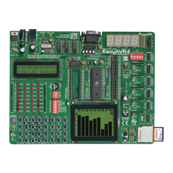
EasyAVR4
Advertisement
Table of Contents

Related Manuals for mikroElektronika EasyAVR4


Summary of Contents for mikroElektronika EasyAVR4
- Page 1 USB 2.0 USB 2.0 ATMEL ATMEL boards (Serial Ethernet, Compact Flash, MMC/SD, ADC, DAC, CAN, RTC, RS-485, etc.), MikroElektronika development boards make fast and reliable tools that DEVELOPMENT DEVELOPMENT can satisfy the needs of experienced engineers and BOARD...
- Page 2 CONSTRUED AS A COMMITMENT BY MIKROELEKTRONIKA MikroElektronika assumes no responsibility or liability for any errors or inaccuracies that may appear in this manual, including the product and software described in it. Product and corporate names appearing in this manual may or may not be registered trade- marks or copyrights of their respective companies, and are used only for identification or explanation and to the owners benefit, without intent to infringe.
-
Page 3: Table Of Contents
EasyAVR4 User’s Manual MikroElektronika Development tools CONTENTS page 4 CONNECTING THE SYSTEM INTRODUCTION page 5 DESCRIPTION OF THE DEVELOPMENT SYSTEM page 5 Switches page 6 Jumpers page 7 MCU sockets page 8 Power Supply page 10 On-board USB 2.0 programmer... -
Page 4: Connecting The System
Run and use AVRprog as explained in the document ‘AVRprog programmer’. CD_Drive:\product\pdf\avrprog_manual.pdf. After these 4 steps, your EasyAVR4 is installed and ready for use. You can try to read a pro- gram from the chip or to load an example from the examples folder of mikroElektronika’s compilers for AVR or from the product CD: CD_Drive:\product\zip\easyavr4_examples.zip. -
Page 5: Introduction
MikroElektronika Development tools INTRODUCTION ATMEL ATMEL The EasyAVR4 development system is a full-featured development board for Atmel AVR DEVELOPMENT DEVELOPMENT BOARD BOARD microcontrollers. It has been designed to allow students and engineers to easily exercise and explore the capabilities of AVR microcontrollers. It allows AVR microcontrollers to be inter- faced with external circuits and a broad range of peripheral devices, allowing a user to con- centrate on software development. -
Page 6: Switches
SWITCHES The EasyAVR4 development board features a number of peripherial devices. In order to enable these devices before programming, you need to check if appropriate jumpers or switches have been properly set. Switches are devices that have two positions - ON and OFF, which have a role to establish or break a connection between two contacts. -
Page 7: Jumpers
EasyAVR4 User’s Manual MikroElektronika Development tools JUMPERS Jumpers, like switches, can break or establish a connection between two points. Beneath the plastic cover of the jumper is a metal contact, which makes a connection if the jumper is placed between two disconnected pins. -
Page 8: Mcu Sockets
MikroElektronika Development tools MCU SOCKETS EasyAVR4 is delivered with a ATmega16 40-pin microcontroller. Users can remove this one and fit a different microcontroller in DIP40, DIP28, DIP20, DIP18, DIP14 or DIP8 packages of an adequate pinout. Figure 5. MCU sockets There are two DIP40 sockets, with different pinouts (SKT1 and SKT2). - Page 9 EasyAVR4 User’s Manual MikroElektronika Development tools Microcontroller’s pins are routed to various peripherals as illustrated in Fig. 6. All ports have direct connections to Direct Port Access connectors. Such connectors are typically used for connecting external peripherals to the board or for providing useful points for connecting digital logic probe.
-
Page 10: Power Supply
PC using the USB programming cable, while the jumper J10 should be set in the right-hand position. In the case of an external power supply, the EasyAVR4 board produces +5V using an LM7805 voltage regulator. The external power supply can be AC or DC, with a voltage between 8V and 16V and the jumper J10 should be set in the left-hand position. -
Page 11: On-Board Usb 2.0 Programmer
IN-CIRCUIT equipment during programming, as the PROGRAMMER PROGRAMMER EasyAVR4 development system has its own on-board USB 2.0 programmer. All you need to do is connect the system to a PC using the USB cable. Then, load your program into the microcontroller via the AVRprog programming software, which is supplied with the board. -
Page 12: Oscillator
OSCILLATOR EasyAVR4 development board has on-board oscillator circuit for generating microcon- troller’s clock input. Within the AVRprog programmer you can either choose internal RC oscillator or external clock. External oscillator is connected to the XT1 pin of the microcon- troller. - Page 13 EasyAVR4 User’s Manual MikroElektronika Development tools Oscillator connection with MCU Figure 13. AREF AGND AVCC OSCILLATOR 74HC04 R7 1M 8MHz OSCILLATOR Note: In order to simplify the schematics in this man- ual, the oscillator circuit is represented by this symbol.
-
Page 14: Leds
LEDs Light Emitting Diodes (LEDs) are the most commonly used components, usually for dis- playing pin’s digital state. EasyAVR4 has 32 LEDs that are connected to the microcon- troller’s PORTA, PORTB, PORTC and PORTD. Figure 14. Light Emitting Diodes Each group of eight LEDs can be enabled or disabled using the switch SW2. - Page 15 EasyAVR4 User’s Manual MikroElektronika Development tools The LEDs are enabled when the corresponding switch on SW2 is on. When enabled, LEDs will display the state of the corresponding microcontroller pin; otherwise the LEDs will always be off, no matter what the port state is, as no current can flow through LED.
-
Page 16: Pushbutton Switches
Development tools PUSHBUTTON SWITCHES EasyAVR4 has 32 push buttons, which can be used to change states of digital inputs to microcontroller's ports. There is also one switch that acts as a RESET. Reset switch schematic is shown in Figure 17. - Page 17 EasyAVR4 User’s Manual MikroElektronika Development tools Buttons connections to PORTA, PORTB, PORTC and PORTD are shown in Fig. 19. Jumper J6 determines whether a button press will bring logical zero or logical one to the appropri- ate pin. When button is not pressed, pin state is determined by the pull-up or pull-down port jumpers.
- Page 18 EasyAVR4 User’s Manual MikroElektronika Development tools On Fig. 20 the J1 jumper is set to pull-up, therefore when the PORTA button is not pressed, pull-up pull-up resistor pulls the microcon- troller’s PA3 pin to +5V. A button press causes the port pin to be connected to ground (J6 is in the lower position).
-
Page 19: 7-Segment Displays
EasyAVR4 User’s Manual MikroElektronika Development tools 7-SEGMENT DISPLAYS EasyAVR4 has four 7-segment displays in multiplex mode. Data lines are connected to PORTA, while each display is enabled through the lower four bits of PORTB. Figure 22. 7-segment displays DIS3 DIS2... -
Page 20: Graphic Lcd
EasyAVR4 User’s Manual MikroElektronika Development tools GRAPHIC LCD GRAPHIC LCD GRAPHIC LCD CONNECTOR CONNECTOR A graphic LCD (GLCD) allows advanced visual messages to be displayed. While a charac- ter LCD can display only alphanumeric characters, a GLCD can be used to display mes-... -
Page 21: Lcd 2X16 In 4-Bit Mode
The character LCD communicates with the microcontroller via a 4-bit or 8-bit data bus, each requiring the use of a different connector on EasyAVR4. For 4-bit data bus use, the LCD should be placed in the upper left of the board, just above the LEDs. The connection to the microcontroller is shown in Fig. -
Page 22: Lcd 2X16 In 8-Bit Mode
It is important to note that the LCD should be placed or removed from EasyAVR4 only when the power is off. Before attaching the LCD, set jumper J8 to the lower position. The LCD's contrast can be adjusted using potentiometer P1 which is located to the right of the GLCD/LCD connector. - Page 23 EasyAVR4 User’s Manual MikroElektronika Development tools In order to enable LCD, jumper J8 should be set to the lower position, labeled as CHAR. GRAPH. GLCD contrast LCD8 contrast GLCD and LCD8 selected selected contrast not selected CHAR. P1 10K Leave four free pins...
-
Page 24: Rs-232 Communication
EasyAVR4 User’s Manual MikroElektronika Development tools RS232 RS232 RS-232 COMMUNICATION RS-232 communication enables point-to-point data transfer. It is commonly used in data ENABLED ENABLED acquisition applications, for the transfer of data between the microcontroller and a PC. Since the voltage levels of a microcontroller and PC are not directly compatible with each other, a level transition buffer such as the MAX232 must be used. - Page 25 EasyAVR4 User’s Manual MikroElektronika Development tools Figure 32. Connection between microcontroller and a PC RS-232 Receive CONNECT data (Rx) MCU TO PC SERIAL CABLE CONNECT Send PC TO MCU Data (Tx) RS-232 A SUB-D 9p 100nF 10uF 10uF T1OUT R1IN...
-
Page 26: Ds1820 Digital Thermometer
-55°C to 125°C and the accura- cy of +/-0.5°C. It must be placed correctly in the 3- pin socket provided on EasyAVR4, with its rounded side to the lower edge of the board (see Fig. 33) oth- erwise the DS1820 could be permanently damaged. -
Page 27: Voltage Regulator
Converter). In order for A/D Converter to work, voltage reference must be used. It repre- sents a maximum value that can be measured by microcontroller. EasyAVR4 uses 4.096V voltage reference because number 4096 is a power of 2 which makes it easy to represent val- ues as binary numbers in microcontroller. - Page 28 EasyAVR4 User’s Manual MikroElektronika Development tools Pull-up/down resistors on PORTA analog input pins should be disabled using PORTA pull-up REF1 AREF 1541 ADC0 10uF VOUT ADC1 ADC2 ADC3 ADC4 ADC5 ADC6 ADC7 AREF AGND OSCILLATOR AVCC 4.096V voltage 5V voltage...
-
Page 29: Direct Port Access
EasyAVR4 User’s Manual MikroElektronika Development tools DIRECT PORT ACCESS All microcontroller input/output pins can be accessed via connectors placed along the right side of the board. For each of PORTA, PORTB, PORTC, PORTD and PORTE there is one 10-pin connector providing VCC, GND and up to eight port pins. - Page 30 EasyAVR4 User’s Manual MikroElektronika Development tools Pull-up line is connected Pull-down line All lines is connected are disconnected RPACK8/9 AREF 8x10K AGND OSCILLATOR AVCC Figure 39. PORTC connection HEADER 5x2 page M I K R O E L E K T R O N I K A S O F T W A R E A N D H A R D W A R E S O L U T I O N S F O R T H E E M B E D D E D W O R L D...
-
Page 31: Jtag Connector
EasyAVR4 User’s Manual MikroElektronika Development tools JTAG CONNECTOR JTAG connector can be used as serial programming interface or On-Chip debug system. For the On-chip Debug system, in addition to the JTAG interface pins, the RESET pin is mon- itored by the debugger to be able to detect external reset sources. The debugger can also pull the RESET pin low to reset the whole system. -
Page 32: Mmc/Sd (Multimedia Card)
SPI comunnication lines (SDI, SDO and SCK) and Chip Select are connected to MMC. Working voltage of EasyAVR4 is 5V DC, while working voltage of MMC card is 3.3V DC. Because of that, there is a voltage regulator on-board with MMC card (MC33269DT-3.3). - Page 33 EasyAVR4 User’s Manual MikroElektronika Development tools SPI-SDI MMC-CS# SPI-SDO SPI-SCK VCC3 CN12 +3.3V MMC/SD CARD Dout REG2 VCC3 MC33269 DT-3.3 100nF 100nF VOUT VCC3 10uF SPI-SCK SPI-SDI SPI-SDO MMC-CS# AREF AGND OSCILLATOR AVCC Figure 42. MMC schematic page EasyAVR M I K R O E L E K T R O N I K A S O F T W A R E A N D H A R D W A R E S O L U T I O N S F O R T H E E M B E D D E D W O R L D...
- Page 34 EasyAVR4 User’s Manual MikroElektronika Development tools If you are experiencing problems with any of our products or you just want additional information, please let us know. We are committed to meeting your every need. Technical Support : support@mikroe.com If you have any other question, comment...
Need help?
Do you have a question about the EasyAVR4 and is the answer not in the manual?
Questions and answers