Table of Contents
Advertisement
Quick Links
UNI-DS6
™
User manual
All MikroElektronika´s development systems represent irreplaceable
tools for programming and developing microcontroller-based devices.
Carefully chosen components and the use of machines of the last
generation for mounting and testing thereof are the best guarantee of
high reliability of our devices. Due to simple design, a large number of
add-on modules and ready to use examples, all our users, regardless
of their experience, have the possibility to develop their project in a fast
and efficient way.
Advertisement
Table of Contents

Related Manuals for mikroElektronika UNI-DS6


Summary of Contents for mikroElektronika UNI-DS6
-
Page 1: User Manual
UNI-DS6 ™ User manual All MikroElektronika´s development systems represent irreplaceable tools for programming and developing microcontroller-based devices. Carefully chosen components and the use of machines of the last generation for mounting and testing thereof are the best guarantee of high reliability of our devices. Due to simple design, a large number of... - Page 2 TO OUR VALUED CUSTOMERS I want to express my thanks to you for being interested in our products and for having confidence in Mikroelektronika. The primary aim of our company is to design and produce high quality electronic products and to constantly improve the performance thereof in order to better suit your needs.
-
Page 3: Table Of Contents
UNI-DS6 Table of Contents General information ����������������������������������������������������������������������������������������������������������4 Key features ���������������������������������������������������������������������������������������������������������������������5 1� Connecting UNI-DS6 to power supply module �������������������������������������������������������������6 2� mikroBoard �������������������������������������������������������������������������������������������������������������������7 3� Placing mikroBoard ������������������������������������������������������������������������������������������������������8 4� Programming microcontroller ���������������������������������������������������������������������������������������9 5� USB UART1 and USB UART2 modules ���������������������������������������������������������������������10 6� ADC module �������������������������������������������������������������������������������������������������������������� 11 7�... -
Page 4: General Information
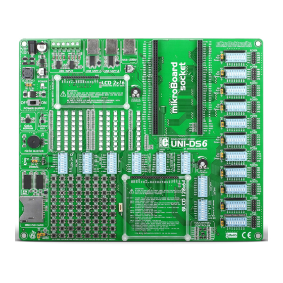
UNI-DS6 General information The UNI-DS6 development system provides a development environment for programming and experimenting with various microcontrollers from different manufacturers� Numerous modules, such as 128x64 graphic LCD display, 2x16 alphanumeric LCD display, piezo buzzer, USB-UART, etc� are provided on the board and allow you to easily simulate the operation of your target device�... -
Page 5: Key Features
UNI-DS6 Key features 13� GLCD display connector 1� Power supply module 14� Touch panel connector 2� ADC input 15� DIP switches for enabling on-board modules 3� USB UART1 module 16� Push buttons 4� USB UART2 module 17� Jumper used to shorten protective resistor 5�... -
Page 6: 1� Connecting Uni-Ds6 To Power Supply Module
UNI-DS6 1. Connecting UNI-DS6 to power supply module In order to enable the development system to be turned on, it is necessary to provide the appropriate power supply voltage over an AC/DC connector CN19, Figure 1-1� When the development system is powered, it is necessary to set switch marked POWER SUPPLY to the ON position�... -
Page 7: 2� Mikroboard
UNI-DS6 2. mikroBoard mikroBoard is designed for placing microcontroller on a development system� Every mikroBoard features an integrated programmer that is used for MCU programming� For connection with a development system, the mikroBoard uses two 2x40 male headers� In addition, the mikroBoard can be used as a standalone device�... -
Page 8: 3� Placing Mikroboard
UNI-DS6 3. Placing mikroBoard The UNI-DS6 development system is designed for usage with various mikroBoards� All the mikroBoards are placed in a universal mikroBoard socket , Figure 3-1� This socket consists of two 2x40 female headers� To place mikroBoard in... -
Page 9: 4� Programming Microcontroller
- mikroBoard for PSoC: PSoC Flash - mikroBoard for dsPIC 80-pin, mikroBoard for PIC 40-pin, mikroBoard for PIC 80-pin: mikroProg Suite for PIC - mikroBoard for ARM 64-pin, mikroBoard for 144-pin: ARMflash To download flash software visit Mikroelektronika’s website at www.mikroe.com MikroElektronika... -
Page 10: 5� Usb Uart1 And Usb Uart2 Modules
5. USB UART1 and USB UART2 modules USB UART modules enable the UNI-DS6 development system to be connected to a PC via a USB connector� In addition to PC, the development system can also be easily connected to other devices that use USB communication�... -
Page 11: 6� Adc Module
UNI-DS6 6. ADC module The ADC module is used to convert an analog voltage level into the appropriate 12-bit digital value� The analog voltage is supplied via screw terminals CN15 and CN16� The voltage supplied via the VREF pin is used as a voltage reference�... -
Page 12: 7� Usb Communication
UNI-DS6 7. USB communication The UNI-DS6 development system can communicate with external devices via the USB connector used for USB communication� The USB connector is directly connected to the microcontroller pins used for USB communication� CN36 USB-VBUS #SS1# #SS2# USB-DN... -
Page 13: 9� Piezo Buzzer
9. Piezo buzzer Due to a built-in piezo buzzer, the UNI-DS6 development system is capable of emitting audio signals� In order to enable the piezo buzzer to operate properly it is necessary to generate a voltage signal of specific frequency. Remember, when writing code for voltage signal generation, that the piezo buzzer’s resonant frequency is 3�8kHz�... -
Page 14: 10� Ds1820 Temperature Sensor
UNI-DS6 10. DS1820 temperature sensor DS1820 is a temperature sensor that uses 1-wire communication for its operation� It is used to measure temperature in a range between -55 and 125°C and provides ±0�5°C accuracy for temperatures in a range between -10 and 85°C� The power supply voltage of 3�3V to 5V is used for the operation of this sensor�... -
Page 15: 11� Mmc/Sd Connector
UNI-DS6 11. MMC/SD connector The UNI-DS6 development system is capable of reading memory cards due to the on-board MMC/SD connector� Memory card communicates with the microcontroller through the microcontroller pins used for serial communication� In order to establish connection between MMC/SD cards and the microcontroller, it is necessary to set switches 1, 2 and 3 (optionally 4, 5 and 6) on the DIP switch SW14, as well as switch 8 on the DIP switch SW13 to the ON position�... -
Page 16: 12� Leds
12. LEDs There are 72 LEDs on the UNI-DS6 development system used to visually indicate the state of each microcontroller I/O pin� An active LED indicates that a logic one (1) is present on the pin� In order to enable LEDs to illuminate, it is necessary to select the appropriate port (PORTA, PORTB, PORTC, PORTD, PORTE or PORTF/G) by using DIP switch SW12�... -
Page 17: 13� Push Buttons
UNI-DS6 13. Push buttons The logic level of all microcontroller input pins may be changed by using push buttons� Jumper J13 is used to determine the logic level to be supplied on the appropriate microcontroller pin by pressing a push button� The function of the protec- tive resistor is to limit the maximum current, thus preventing the development system and peripheral modules from being damaged in case a short circuit occurs�... -
Page 18: 14� 2X16 Lcd Display
UNI-DS6 14. 2x16 LCD display The UNI-DS6 development system features an on-board connector for the alphanumeric 2x16 LCD display� This connector is linked to the microcontroller via DIP switches (SW18 (PORTA) or SW15 (PORTB)) and (SW16 (PORTD) or SW17 (PORTC)) � Potentiometer P1 is used to adjust display contrast� The LCD-BCK switch on the DIP switch SW18 is used to turn the display backlight on/off�... -
Page 19: 15� 128X64 Graphic Lcd Display
UNI-DS6 15. 128x64 graphic LCD display 128x64 graphic LCD (GLCD) is connected to the microcontroller via DIP switches (SW18 (PORTA) or SW15 (PORTB)) and (SW16 (PORTD) or SW17 (PORTC))� It has a screen resolution of 128x64 pixels, which allows diagrams, tables and other graphic contents to be displayed�... -
Page 20: 16� Touch Panel
UNI-DS6 16. Touch panel A touch panel is a thin, self-adhesive, transparent, touch-sensitive panel� It is placed over a GLCD display� Its main function is to register pressure at some specific display point and to forward its coordinates in the form of analog voltage to the microcontroller�... -
Page 21: 17� Input/Output Ports
UNI-DS6 17. Input/output ports Along the right side of the development system, there are eleven 10-pin connectors linked to the microcontroller I/O ports� Pull-up or pull-down resistors can be connected to I/O ports via jumpers J1-J11 and DIP switches SW1-SW11�... - Page 22 UNI-DS6 Pull-up/pull-down resistors enable you to feed all microcontroller’s input pins with logic level when they are in idle state� This level depends on the position of the pull-up/pull-down jumper (J1-J11)� The RA0 pin with the relevant jumper J1 and RA0 push button with jumper J13 are used here for the purpose of explaining the performance of pull-up/pull-down resistors�...
- Page 23 MikroElektronika has been advised of the possibility of such damages. MikroElektronika reserves the right to change information contained in this manual at any time without prior notice, if necessary.
- Page 25 Mouser Electronics Authorized Distributor Click to View Pricing, Inventory, Delivery & Lifecycle Information: MikroElektronika MIKROE-701...
Need help?
Do you have a question about the UNI-DS6 and is the answer not in the manual?
Questions and answers