Table of Contents
Advertisement
Quick Links
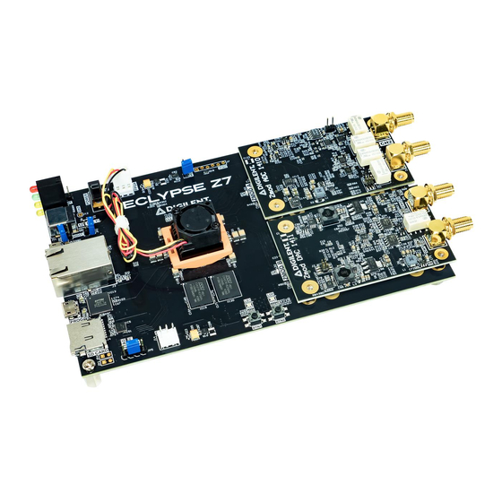
Eclypse Z7 Hardware Reference Manual
The Eclypse Z7 is a powerful prototyping platform, featuring Xilinx's Zynq-7000 APSoC.
Two SYZYGY interface connectors are featured, enabling high speed modular systems.
Eclypse is designed to enable high speed analog data capture and analysis right out of
the box. It is a platform for research and rapid prototyping of test and measurement
applications, potentially including software defined radio, ultrasound, other medical
devices, and much more. As a host board for Zmods, applications for the Eclypse can
vary significantly between system configurations.
Petalinux is supported out of the box. Pre-built Linux images are accompanied by a
software API for bulk data transfer. This system allows new users to get started without
touching hardware until desired. The software supports a variety of common
programming languages, including Python, C/C++, and more. Digilent offers fully open
and customizable hardware designs, Linux images, and Linux software applications.
Advertisement
Table of Contents

Related Manuals for Digilent Eclypse Z7


Summary of Contents for Digilent Eclypse Z7
- Page 1 Eclypse Z7 Hardware Reference Manual The Eclypse Z7 is a powerful prototyping platform, featuring Xilinx's Zynq-7000 APSoC. Two SYZYGY interface connectors are featured, enabling high speed modular systems. Eclypse is designed to enable high speed analog data capture and analysis right out of the box.
- Page 2 Features • Zynq-7000 APSoC (XC7Z020-1CLG484C) 667 MHz dual-core Cortex-A9 processor DDR3L memory controller with 8 DMA channels and 4 High Performance AXI3 Slave ports High-bandwidth peripheral controllers: 1G Ethernet, USB 2.0, SDIO Low-bandwidth peripheral controllers: SPI, UART, CAN, I2C Programmable from JTAG, Quad-SPI flash, and microSD card Programmable logic equivalent to Artix-7 FPGA •...
- Page 3 Eclypse Z7 Callout Diagram Callout Callout Callout Description Description Description Board Indicator SYZYGY Ports Reset Buttons LEDs (LD4) (underside of board) Header for Case Pmod Ports microSD Card Slot Power Switch Power Switch User Buttons and USB JTAG/UART Port LEDs...
-
Page 4: Software Support
A USB A to Micro B programming cable, a USB A to Micro A cable, and a 12V 5A power supply, are included with the Eclypse Z7. An Eclypse Z7 Enclosure Kit may optionally be added on, which provides a sturdy case for the Eclypse platform. -
Page 5: Zynq Apsoc Architecture
Zynq APSoC Architecture The Zynq APSoC is divided into two distinct subsystems: The Processing System (PS) and the Programmable Logic (PL). The figure below shows an overview of the Zynq APSoC architecture, with the PS colored light green and the PL in yellow. Note that the PCIe Gen2 controller and Multi-gigabit transceivers are not available on the Zynq-7020 device. - Page 6 Reference manual. The tables in the dropdowns below depict the external components connected to the MIO pins of the Eclypse Z7. The Vivado board files found on the Eclypse Z7 Resource Center can be used to properly configure the PS to work with these peripherals. It is also possible to use the example projects found on the resource center as a starting point for custom designs.
- Page 7 Ethernet Reset 10 (N/A) 11 (N/A) DNA SCL (I2C 0) DNA SDA (I2C 0) UART Input UART Output MIO 16-53 : Bank 501 MIO 501 1.8V Peripherals ENET 0 USB 0 SD 0 TXCK TXD0 TXD1 TXD2 TXD3...
- Page 8 TXCTL RXCK RXD0 RXD1 RXD2 RXD3 RXCTL DATA4 DATA0 DATA1 DATA2...
- Page 9 DATA3 DATA5 DATA6 DATA7 CCLK USB Reset Ethernet Interrupt (GPIO)
- Page 10 MDIO Functional Description 1. Power Supplies The Eclypse Z7 power circuitry was carefully designed to meet the requirements of the Zynq-7000 and all peripherals while providing the flexibility needed to power a variety of different configurations of Zmod/SYZYGY modules. An overview of the power circuit is shown in Figure 1.1.
- Page 11 LD3 is associated with Zmod Port B and the VADJB rail. 1.1. Power Input Source The Eclypse Z7 should be powered via a wall wart supply with barrel jack, via the barrel connector (J11). The supply must use a center-positive 2.1 mm internal-diameter plug and deliver between 11.5V and 12.5V DC.
- Page 12 The power budget of VCC5V0 is shared by the SYZYGY ports, USB OTG VBUS, RGB LEDs, and Case Fan. As such, the actual maximum current achievable by each peripheral varies with the Eclypse Z7's system configuration. Under worst-case conditions, VCC5V0 is capable of outputting a minimum of 3A of continuous current. In...
- Page 13 Zmod installed in the system. The 5V power budget of the Eclypse is then determined based on the needs of each Zmod, as well as the USB OTG VBUS, RGB LEDs, and Fan. Table 1.2.2 describes the 5V power budget of the Eclypse Z7 in more detail.
- Page 14 Port Rail Max Capacitance (µF) Zmod Port A 1000 Zmod Port B VCC5V0 Zmod Port B VCC3V3 Zmod Port B 1000 Pmod Port A VCC3V3 Pmod Port B VCC3V3 1.3. Power Sequencing A custom power sequencer (IC29) is used to sequence the power supplies on in the correct order when the power switch is placed in the “ON”...
- Page 15 1.4. FPGA Fan The FPGA fan is to be connected to the Eclypse Z7 via fan header J8 (labeled “FPGA”) and is powered by VADJC, an adjustable rail controlled by the Platform MCU. The FPGA fan's speed can be configured to Automatic (the default factory setting), High, Medium, Low, or Off, by communicating with the PMCU through its I2C interface.
- Page 16 PMCU Interface Connection PORT_A, VADJ_A Zmod A PORT_B, VADJ_B Zmod B FAN_1 FPGA Fan FAN_2 Case Fan Table 1.6.2: Supported Platform MCU Optional Features Optional Features Supported DDRVCCSEL Control INIT_B Control USB Hub Support Table 1.6.3: Supported Platform MCU Fan COntrol Features Feature FAN_1 (FPGA Fan) FAN_2 (Case Fan)
-
Page 17: Zynq Configuration
The boot process is broken into three stages: Stage 0 After the Eclypse Z7 is powered on or the Zynq is reset (in software or by pressing the PS-SRST button, BTNR), one of the processors (CPU0) begins executing an internal piece of read-only code called the BootROM. - Page 18 3. Rename the Zynq Boot Image on the microSD card to BOOT.bin. 4. Eject the microSD card from your computer and insert it into J4 on the Eclypse Z7. 5. Attach a power supply to the Eclypse Z7 via the barrel jack (J11).
- Page 19 This can be done using the Vivado Hardware Server. The Eclypse Z7 is configured to boot in Cascaded JTAG mode, which allows the PS to be accessed via the same JTAG port as the PL. It is also possible to boot the Eclypse Z7 in Independent JTAG mode by shorting unloaded jumper JP3.
-
Page 20: Quad-Spi Flash
PS and PL of the Zynq device with a Zynq Boot Image (also known as BOOT.BIN) generated using Xilinx tools such as Petalinux or Xilinx SDK. For information on booting the Eclypse Z7 with a Zynq Boot image, see section “2.2 Quad SPI Boot Mode”. - Page 21 Flash. A globally unique MAC address is programmed into the One-Time-Programmable (OTP) region of the Flash on each Eclypse Z7 at the factory. For more information on this, see section Ethernet. The MAC address can also be found on a sticker attached to the board.
-
Page 22: Reset Sources
This signal resets every register in the device capable of being reset. The Eclypse Z7 drives this signal from the VCC4V3 supply, the final non- adjustable supply to be brought up in the power-on sequence, in order to hold the system in reset until all power supplies are valid. -
Page 23: Processor Subsystem Reset
System reset does not cause the boot mode strapping pins to be re-sampled. After changing the boot mode jumper a power cycle is needed to act on the new setting. BTNR is located on the underside of the Eclypse Z7, below the SD card slot. - Page 24 I/O bank of the Zynq dedicated to it, which is powered by a dedicated adjustable rail, configured by the Platform MCU as the Eclypse is powered on. Template constraints for each Zmod port can be found in the Eclypse Z7's Master XDC file, available through Digilent's digilent-xdc repository on Github.
-
Page 25: Microsd Slot
73.7 mm +- 0.2 mm (including Zynq package delay) 9. microSD Slot The Eclypse Z7 provides a microSD slot (J4) for non-volatile external memory storage as well as booting the Zynq. The slot is wired to Bank 1/501 MIO[40-45], and also... - Page 26 2-port SDIO port expander, but only its level shifter function is used. The connection diagram can be seen on Figure 9.1. Mapping out the correct pins and configuring the interface is handled by the Eclypse Z7 board files, available on Eclypse Z7 Resource...
- Page 27 /dev/mmcblk0. See the Petalinux and Xilinx SDK documentation for more information. 10. USB Micro-AB Device/Host/OTG Port The Eclypse Z7 implements one of the two available PS USB OTG interfaces on the Zynq device. A Microchip USB3320 USB 2.0 Transceiver Chip with an 8-bit ULPI interface is used as the PHY.
- Page 28 Table 10.1. Whether the Eclypse Z7 is configured as an embedded host or a general purpose host, it can provide at least 500 mA on the 5V VBUS line. More than 500 mA of current can potentially be provided depending on the system configuration and how much power is drawn by installed Zmods.
- Page 29 Figure 11.1: Ethernet PHY signals Two status indicator LEDs are located on the RJ-45 connector (J3) that indicate traffic (J3/LD2, right side of connector) and valid link state (J3/LD1, left side of connector). Table 11.1 shows the default behavior. Table 11.1: Ethernet status LEDs Function Designator State...
- Page 30 U-boot boot-loader, and the Linux system is automatically configured to use this unique MAC address. The identifier is also printed on a sticker found on the top-side of the Eclypse Z7 right next to the mode jumper (JP5) and above the headphone output jack.
- Page 31 12. Basic I/O The Eclypse Z7 includes two push-buttons and two tri-color LEDs connected to the Zynq PL, as shown in Figure 12.1. These I/Os are connected to the Zynq via series resistors to prevent damage from inadvertent short circuits (a short circuit could occur if a pin assigned to a push-button was inadvertently defined as an output).
- Page 32 See the Pmod-related tutorials on the Eclypse Z7 Resource Center for help using them. The Eclypse Z7's two Pmod ports are connected to the Zynq PL via high-speed down translation and protection circuitry. When used as outputs, the Pmod pins are driven at 3.3V.
Need help?
Do you have a question about the Eclypse Z7 and is the answer not in the manual?
Questions and answers