Table of Contents
Advertisement
22.8.2018
Cmod S7 Reference Manual
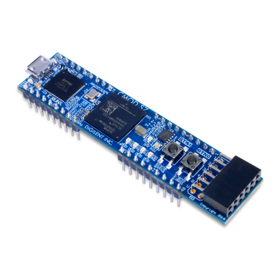
The Digilent Cmod S7 is a small, 48-pin DIP form factor board built around a Xilinx Spartan 7 FPGA. 32 FPGA digital I/O signals, 2
FPGA analog input signals, an external power input rail, and ground are routed to 100-mil-spaced through-hole pins, making the Cmod
S7 well suited for use with solderless breadboards. At just 0.7" by 3.05" inches, it can be loaded in a standard socket and used in
embedded systems. The board also includes a programming ROM (), clock source, USB programming and data transfer circuit, power
supplies, LEDs, and buttons.
(https://reference.digilentinc.com/_media/reference/programmable-logic/cmod-s7/cmod_s7-obl-600.png)
https://reference.digilentinc.com/reference/programmable-logic/cmod-s7/reference-manual
Cmod S7 Reference Manual [Reference.Digilentinc]
1/12
Advertisement
Table of Contents

Subscribe to Our Youtube Channel
Related Manuals for Digilent Cmod S7


Summary of Contents for Digilent Cmod S7
- Page 1 Cmod S7 Reference Manual The Digilent Cmod S7 is a small, 48-pin DIP form factor board built around a Xilinx Spartan 7 FPGA. 32 FPGA digital I/O signals, 2 FPGA analog input signals, an external power input rail, and ground are routed to 100-mil-spaced through-hole pins, making the Cmod S7 well suited for use with solderless breadboards.
- Page 2 22.8.2018 Cmod S7 Reference Manual [Reference.Digilentinc] Features Xilinx Spartan-7 FPGA (XC7S25-1CSGA225C) https://reference.digilentinc.com/reference/programmable-logic/cmod-s7/reference-manual 2/12...
-
Page 3: Software Support
Software Support The Cmod S7 is fully compatible with the high-performance Vivado ® Design Suite versions 2018.1 and newer. It is supported under the free WebPACK™ installation option, which does not require a license, so designs can be implemented at no additional cost. This free installation includes the ability to create MicroBlaze™... -
Page 4: Functional Description
1.1 Power Input Options It is possible to power the Cmod S7 from either USB or from an external power supply attached to pins 24 and 25 of the DIP headers, labeled “VU” and “GND ()”, respectively. The required characteristics of a power source attached to either of these two options is outlined in Table 1.1.1. -
Page 5: Fpga Configuration
When the Cmod S7 is powered by the USB connector, the voltage from the USB device is driven onto the VU pin. This makes it possible to power an external circuit from the USB host in addition to the Cmod S7. The VU pin is driven via a schottky diode, so a small voltage drop will occur, but it should be assumed that the voltage present on VU will be close to 5V. -
Page 6: Quad-Spi Flash
4 Oscillators/Clocks The Cmod S7 includes a 12 MHz () crystal oscillator connected to pin M9 (an MRCC input on bank 14). This clock is intended to be used as a general purpose system clock. The clock can drive MMCMs to generate clocks of various frequencies and with known phase relationships that may be needed throughout a design. -
Page 7: Usb-Uart Bridge (Serial Port)
6 Basic I/O The Cmod S7 includes one RGB LED (), 4 individual LEDs, and 2 push buttons, as shown in Figure 6.1. The push buttons are connected to the FPGA via series resistors to prevent damage from inadvertent short circuits (a short circuit could occur if an FPGA pin assigned to a button was inadvertently defined as an output). - Page 8 7 DIP Header The Cmod S7 has a 48-pin DIP form factor connector, implemented as four 9-pin headers for connecting to breadboards and custom fixtures. The pins have 100 mil spacing, and the entire module is 0.7 inches by 3.05 inches. Headers J1 and J3 are separated by 700 mil lengthwise along the Cmod, measured from the center of the innermost pins, as are headers J2 and J4.
-
Page 9: Analog Inputs
Figure 7.1 DIP Pin Diagram VU (pin 24) can be used to power the Cmod S7 when it is not connected to a USB Host. When the device is connected to a USB host, VU is driven by the 5V rail of the USB connector and can be used to power devices external to the Cmod S7. See the Power Supplies section for more information. -
Page 10: Pmod Connector
The Cmod S7 has one “standard” type Pmod connector, and the FPGA pin connections for it are described in Table 8.1. Standard Pmod connectors are connected to the FPGA via 200 Ohm series resistors. The series resistors prevent short circuits that can occur if a user accidentally drives a signal that is supposed to be used as an input. - Page 11 22.8.2018 Cmod S7 Reference Manual [Reference.Digilentinc] Pmod JA Pin 8 Pin 9 Pin 10 Table 8.1. Cmod S7 Pmod Pinout cmod-s7 , doc (https://reference.digilentinc.com/tag/cmod-s7?do=showtag&tag=cmod-s7) (https://reference.digilentinc.com/tag/doc? do=showtag&tag=doc) Subscribe to our Newsletter First Name Last Name Email Address Submit Our Partners Help...
- Page 12 22.8.2018 Cmod S7 Reference Manual [Reference.Digilentinc] (https://instagram.com/digilentinc) (https://github.com/digilent) (https://www.reddit.com/r/digilent) (https://www.linkedin.com/company/1454013) (https://www.flickr.com/photos/127815101@N07) https://reference.digilentinc.com/reference/programmable-logic/cmod-s7/reference-manual 12/12...
Need help?
Do you have a question about the Cmod S7 and is the answer not in the manual?
Questions and answers