Table of Contents
Advertisement
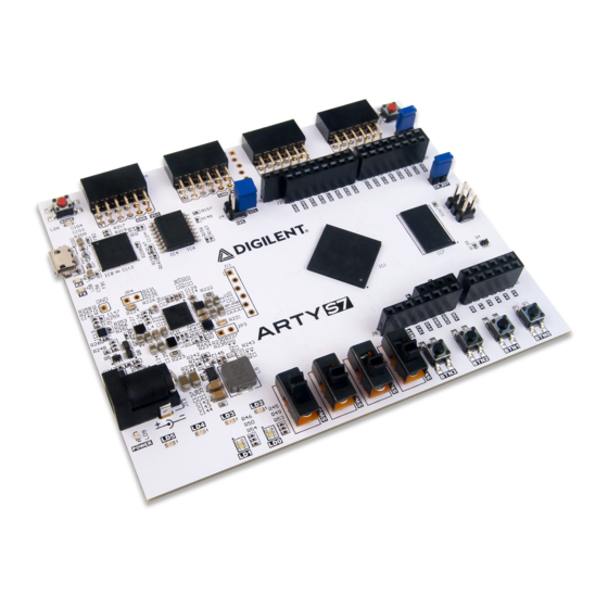
Arty S7 Reference Manual
The Arty S7 board features the new Xilinx Spartan-7 FPGA and is the latest member of the Arty FPGA development board family from Digilent. The Spartan-7 FPGA offers the most
size, performance, and cost-conscious design engineered with the latest technologies from Xilinx and is fully compatible with Vivado Design Suite. Putting this FPGA in the Arty form
factor provides users with a wide variety of I/O and expansion options. Use the dual row Arduino® connectors to mount one of the hundreds of hardware compatible shields
available, or use the Pmod ports with Digilent's pre-made Pmod IP blocks for a more streamlined design experience. Arty S7 was designed to be MicroBlaze ready and comes out of
the box ready to use with the free Xilinx WebPack version of Vivado Design Suite.
(https://reference.digilentinc.com/_media/reference/programmable-logic/arty-
s7/arty-s7-0.png)
Advertisement
Table of Contents

Related Manuals for Digilent Arty S7


Summary of Contents for Digilent Arty S7
- Page 1 Arty S7 Reference Manual The Arty S7 board features the new Xilinx Spartan-7 FPGA and is the latest member of the Arty FPGA development board family from Digilent. The Spartan-7 FPGA offers the most size, performance, and cost-conscious design engineered with the latest technologies from Xilinx and is fully compatible with Vivado Design Suite. Putting this FPGA in the Arty form factor provides users with a wide variety of I/O and expansion options.
- Page 4 Features Xilinx Spartan-7 50 FPGA (xc7s50csga324-1) 8,150 slices (each slice contains four 6-input LUTs and 8 flip-flops) 2,700 Kbits of fast block RAM () Five clock management tiles, each with a phase-locked loop (PLL) 120 DSP slices Internal clock speeds exceeding 450MHz On-chip analog-to-digital converter (XADC) Programmable over JTAG and Quad-SPI Flash Memory...
-
Page 5: Software Support
The Arty S7's Soft SoC configurations are powered by MicroBlaze processor cores. MicroBlaze is a 32-bit RISC soft processor core, designed specifically to be used in Xilinx FPGAs. The MicroBlaze processor in an Arty S7 SoC configuration is typically run at 100 MHz (), though it is possible to design your SoC so that it can operate at over 200MHz. The Arty S7... -
Page 6: Functional Description
1 Power Supplies The Arty S7 board requires a 5 volt power source to operate. This power source can come from the Digilent USB-JTAG port (J10) or it can be derived from a 7 to 15 Volt DC power supply that’s connected to the Power Jack (J12) or Pin 8 of Header J7. Header JP13, labeled “5V SELECT”, is used to determine which source is used. -
Page 7: Current Monitoring
PC to the FPGA using the onboard Digilent USB-JTAG circuitry (port J10) or an external JTAG programmer, such as the Digilent JTAG-HS2, attached to port J9. You can perform JTAG programming any time after the Arty S7 has been powered on, regardless of whether the mode jumper (JP1) is set. If the FPGA is already configured, then the existing configuration is overwritten with the bitstream being transmitted over JTAG. -
Page 8: Quad-Spi Flash
.prj file that can be imported into the wizard to automatically configure it with the options found in Table 3.1. For those using the MIG with a MicroBlaze project, it is not necessary to use the files found in the digilent-mig repository. Instead, the Arty S7 MIG settings and pinout will be... -
Page 9: Usb-Uart Bridge (Serial Port)
5 Oscillators/Clocks The Arty S7 board includes a 12 MHz () crystal oscillator connected to pin F14 (an MRCC input on bank 15) and a 100 MHz () crystal oscillator connected to pin R2 (an MRCC input on bank 34). -
Page 10: Tri-Color Leds
7.1 Tri-Color LEDs The Arty S7 board contains two tri-color LEDs. Each tri-color LED () has three input signals that drive the cathodes of three smaller internal LEDs: one red, one blue, and one green. Driving the signal corresponding to one of these colors high will illuminate the internal LED (). The input signals are driven by the FPGA through a transistor, which inverts the signals. - Page 11 9 Arduino/chipKIT Shield Connector The Arty S7 can be connected to standard Arduino and chipKIT shields to add extended functionality. Special care was taken while designing the Arty S7 to make sure it is compatible with the majority of Arduino and chipKIT shields on the market. The shield connector has 45 pins connected to the FPGA for general purpose Digital I/O. Due to the flexibility of FPGAs, it is possible to use these pins for just about anything including digital read/write, SPI connections, UART connections, I2C connections, and PWM.
- Page 12 3.3V. This circuit is shown in Figure 9.2.1. This circuit allows the XADC module to accurately measure any voltage between 0V and 3.3V (relative to the Arty S7's GND ()) that is applied to any of these pins. If you wish to use the pins labeled A0-A5 as Digital inputs or outputs, they are also...
- Page 13 The pins labeled V_P and V_N are connected to the VP_0 and VN_0 dedicated analog inputs of the FPGA. This pair of pins can also be used as a differential analog input with voltage between 0-1V, but they cannot be used as Digital I/O. The capacitor in the circuit shown in Figure 9.2.2 for this pair of pins is loaded on the Arty S7.
- Page 14 (https://www.facebook.com/Digilent) (https://www.youtube.com/user/DigilentInc) (https://instagram.com/digilentinc) (https://github.com/digilent) (https://www.reddit.com/r/digilent) (https://www.linkedin.com/company/1454013) (https://www.flickr.com/photos/127815101@N07)
Need help?
Do you have a question about the Arty S7 and is the answer not in the manual?
Questions and answers