Advertisement
Quick Links
C
e
r
e
b
o
t
M
X
C
e
r
e
b
o
t
M
X
R
e
f
e
r
e
n
c
e
M
R
e
f
e
r
e
n
c
e
M
Revision: September 6, 2012
Note: This document applies to REV B and C of the board.
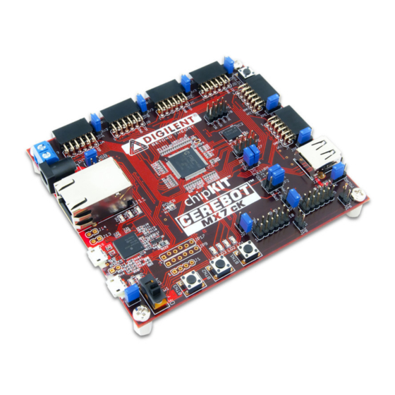
Overview
The Cerebot MX7cK is a microcontroller
development board based on the Microchip
PIC32MX795F512L, a member of the 32-bit
PIC32 microcontroller family. It is compatible
with Digilent's line of Pmod™ peripheral
modules, and is suitable for use with the
®
Microchip MPLAB
IDE tools. The Cerebot
MX7cK is also compatible for use with the
chipKIT™ MPIDE development environment.
ChipKIT and MPIDE is a PIC32 based system
compatible with many existing Arduino™ code
examples, reference materials and other
resources.
The Cerebot MX7cK is designed to be easy to
use and suitable for use by anyone from
beginners to advanced users for experimenting
with embedded control and network
communications application. A built in
programming/debugging circuit compatible with
®
the Microchip MPLAB
additional hardware is required for use with
MPLAB. The kit contains everything needed to
start developing embedded applications using
®
either the MPLAB
IDE or the MPIDE.
The Cerebot MX7cK provides 52 I/O pins that
support a number of peripheral functions, such
2
as UART, SPI and I
C™ ports as well as five
pulse width modulated outputs and five
external interrupt inputs. Its network and
communications features also include a 10/100
Ethernet interface, Full Speed USB 2.0 OTG
interface, and dual CAN network interfaces.
Ten of the I/O pins can be used as analog
inputs in addition to their use as digital inputs
and outputs.
The Cerebot MX7cK can be powered in
various ways via USB, or using an external
AC-DC power adapter.
Doc: 502-223
Copyright Digilent, Inc. All rights reserved. Other product and company names mentioned may be trademarks of their respective owners.
7
c
K
™
B
o
a
r
7
c
K
™
B
o
a
r
a
n
u
a
l
a
n
u
a
l
IDE is provided, so no
d
d
Cerebot MX7cK Circuit Diagram
1300 Henley Court | Pullman, WA 99163
(509) 334 6306 Voice and Fax
page 1 of 34
Advertisement

Related Manuals for Digilent Cerebot MX7cK REV B


Summary of Contents for Digilent Cerebot MX7cK REV B
- Page 1 The Cerebot MX7cK can be powered in various ways via USB, or using an external AC-DC power adapter. Doc: 502-223 page 1 of 34 Copyright Digilent, Inc. All rights reserved. Other product and company names mentioned may be trademarks of their respective owners.
-
Page 2: Functional Description
Microchip web site. This sixteen 10-bit analog inputs • software suite includes a free evaluation copy www.digilentinc.com page 2 of 34 Copyright Digilent, Inc. All rights reserved. Other product and company names mentioned may be trademarks of their respective owners. - Page 3 • Use the “Programmer.Program” command to circuit: program all memories on the device. www.digilentinc.com page 3 of 34 Copyright Digilent, Inc. All rights reserved. Other product and company names mentioned may be trademarks of their respective owners.
- Page 4 This pin is coupled through a capacitor to the www.chipKIT.org/forum MCLR pin on the PIC32 microcontroller. www.digilentinc.com page 4 of 34 Copyright Digilent, Inc. All rights reserved. Other product and company names mentioned may be trademarks of their respective owners.
- Page 5 100mA of current unable to hold the ON/OFF pin low and the www.digilentinc.com page 5 of 34 Copyright Digilent, Inc. All rights reserved. Other product and company names mentioned may be trademarks of their respective owners.
- Page 6 In addition to powering the logic on the Cerebot MX7cK board, this supply provides the www.digilentinc.com page 6 of 34 Copyright Digilent, Inc. All rights reserved. Other product and company names mentioned may be trademarks of their respective owners.
- Page 7 5V0 position to use the unregulated supply. specified input/output voltage range (V 0.4V, 2.4V) the pin current must be restricted to www.digilentinc.com page 7 of 34 Copyright Digilent, Inc. All rights reserved. Other product and company names mentioned may be trademarks of their respective owners.
- Page 8 The PORT register is used to read from the I/O Port. Reading from the PORT register returns www.digilentinc.com page 8 of 34 Copyright Digilent, Inc. All rights reserved. Other product and company names mentioned may be trademarks of their respective owners.
- Page 9 BTN3 is not useable as a button logic high value by a 5V input. input until the JTAG controller is disabled. The www.digilentinc.com page 9 of 34 Copyright Digilent, Inc. All rights reserved. Other product and company names mentioned may be trademarks of their respective owners.
- Page 10 5V is sufficient. A pull-up resistor in the range of 2Kohm–10kOhm can be used. This technique should not be used www.digilentinc.com page 10 of 34 Copyright Digilent, Inc. All rights reserved. Other product and company names mentioned may be trademarks of their respective owners.
- Page 11 Cerebot MX7cK board #pragma config FPLLODIV to set the provides an SMSC LAN8720 Ethernet Physical www.digilentinc.com page 11 of 34 Copyright Digilent, Inc. All rights reserved. Other product and company names mentioned may be trademarks of their respective owners.
- Page 12 PHY to come out of stack, refer to the manufacturer documentation www.digilentinc.com page 12 of 34 Copyright Digilent, Inc. All rights reserved. Other product and company names mentioned may be trademarks of their respective owners.
- Page 13 Jumper JP10 is used to route power to the #pragma config UPLLIDIV = DIV_2 host connector being used. Place the shorting www.digilentinc.com page 13 of 34 Copyright Digilent, Inc. All rights reserved. Other product and company names mentioned may be trademarks of their respective owners.
- Page 14 #pragma config host applications when using the board with statement. To select the use of the alternate www.digilentinc.com page 14 of 34 Copyright Digilent, Inc. All rights reserved. Other product and company names mentioned may be trademarks of their respective owners.
- Page 15 UART1. The MPIDE uses this to communicate provide 120 ohm termination. The Cerebot www.digilentinc.com page 15 of 34 Copyright Digilent, Inc. All rights reserved. Other product and company names mentioned may be trademarks of their respective owners.
- Page 16 SPI3, Pmod connector JE, and the SDO pin. Each time the master sends a byte to www.digilentinc.com page 16 of 34 Copyright Digilent, Inc. All rights reserved. Other product and company names mentioned may be trademarks of their respective owners.
- Page 17 Wire library, or the Digilent DTWI pull-up resistors when no device is driving the library. www.digilentinc.com page 17 of 34 Copyright Digilent, Inc. All rights reserved. Other product and company names mentioned may be trademarks of their respective owners.
- Page 18 Wire object, or using the DTWI library via the reference level. These references can be DTWI1 object class. www.digilentinc.com page 18 of 34 Copyright Digilent, Inc. All rights reserved. Other product and company names mentioned may be trademarks of their respective owners.
- Page 19 Vref+ = voltage at A2 chipKIT MPIDE software. This capability will be added in a future version of the software. www.digilentinc.com page 19 of 34 Copyright Digilent, Inc. All rights reserved. Other product and company names mentioned may be trademarks of their respective owners.
- Page 20 • OC2 – JD-07, digital pin 28, RD01 • OC3 – JD-08, digital pin 29, RD02 www.digilentinc.com page 20 of 34 Copyright Digilent, Inc. All rights reserved. Other product and company names mentioned may be trademarks of their respective owners.
- Page 21 PIC32 microcontroller, IC1, is provided for the user to solder in a 32Khz watch crystal. The www.digilentinc.com page 21 of 34 Copyright Digilent, Inc. All rights reserved. Other product and company names mentioned may be trademarks of their respective owners.
-
Page 22: Appendix A: Connector Descriptions And Jumper Settings
CAN #2 Connector This connector is used to access the signals for CAN #2. Ethernet Connector www.digilentinc.com page 22 of 34 Copyright Digilent, Inc. All rights reserved. Other product and company names mentioned may be trademarks of their respective owners. - Page 23 This jumper is used to enable/disable the 120 ohm termination resistor for CAN #2. Insert the shorting block to enable the termination resistor, remove it to disable the termination resistor. www.digilentinc.com page 23 of 34 Copyright Digilent, Inc. All rights reserved. Other product and company names mentioned may be trademarks of their respective owners.
- Page 24 MPIDE development tools. Remove the shorting block if the USB serial converter is interfering with proper operation of the licensed debugger circuit. JP17 Do Not Use www.digilentinc.com page 24 of 34 Copyright Digilent, Inc. All rights reserved. Other product and company names mentioned may be trademarks of their respective owners.
-
Page 25: Appendix B: Example Of Configuration Values
// Program flash write protect /* Debug settings #pragma config ICESEL = ICS_PGx1 // ICE pin selection www.digilentinc.com page 25 of 34 Copyright Digilent, Inc. All rights reserved. Other product and company names mentioned may be trademarks of their respective owners. -
Page 26: Appendix C: Connector And Jumper Block Pinout Tables
RB13 AN13/ERXD1/AECOL/PMA10/RB13 Ethernet PHY JC-10 RB14 AN14/ERXD2/AETXD3/PMALH/PMA1/RB14 JC-07 RB15 AN15/.../OCFB/PMALL/PMA0/CN12/RB15 JE-01 RD14 AETXD0/SS1A/U1BRX/U1ACTS/CN20/RD14 JE-04 RD15 AETXD1/SCK1A/U1BTX/U1ARTS/CN21/RD15 www.digilentinc.com page 26 of 34 Copyright Digilent, Inc. All rights reserved. Other product and company names mentioned may be trademarks of their respective owners. - Page 27 PMD0/RE0 JB-02 RE01 PMD1/RE1 RG14 TRD2/RG14 LED3 RG12 TRD1/RG12 LED1 RG13 TRD0/RG13 LED2 JB-03 RE02 PMD2/RE2 www.digilentinc.com page 27 of 34 Copyright Digilent, Inc. All rights reserved. Other product and company names mentioned may be trademarks of their respective owners.
- Page 28 Cerebot MX7cK Reference Manual JB-04 RE03 PMD3/RE3 JB-07 RE04 PMD4/RE4 www.digilentinc.com page 28 of 34 Copyright Digilent, Inc. All rights reserved. Other product and company names mentioned may be trademarks of their respective owners.
- Page 29 SCL1A/SDO1A/U1ATX/RF8 JE-03 RF02 SDA1A/SDI1A/U1ARX/RF2 JE-04 RD15 AETXD1/SCK1A/U1BTX/U1ARTS/CN21/RD15 JE-07 RE08 AERXD0/INT1/RE8 JE-08 RA07 TRD3/RA7 JE-09 RA09 Vref-/CVref-/AERXD2/PMA7/RA9 www.digilentinc.com page 29 of 34 Copyright Digilent, Inc. All rights reserved. Other product and company names mentioned may be trademarks of their respective owners.
- Page 30 RC14 SOSCO/T1CK/CN0/RC14 Secondary Oscillator RD06 ETXEN/PMD14/CN15/RD6 Ethernet PHY RF00 C1RX/ETXD1/PMD11/RF0 Ethernet PHY RF01 C1TX/ETXD0/PMD10/RF1 Ethernet PHY www.digilentinc.com page 30 of 34 Copyright Digilent, Inc. All rights reserved. Other product and company names mentioned may be trademarks of their respective owners.
- Page 31 Cerebot MX7cK Reference Manual RA06 TRCLK/RA6 Ethernet PHY Reset www.digilentinc.com page 31 of 34 Copyright Digilent, Inc. All rights reserved. Other product and company names mentioned may be trademarks of their respective owners.
- Page 32 SOSCO/T1CK/CN0/RC14 Secondary Oscillator RC15 OSC2/CLKO/RC15 Primary Oscillator JD-02 RD00 SDO1/OC1/INT0/RD0 JD-07 RD01 OC2/RD1 JD-08 RD02 OC3/RD2 www.digilentinc.com page 32 of 34 Copyright Digilent, Inc. All rights reserved. Other product and company names mentioned may be trademarks of their respective owners.
- Page 33 .../SCL2A/SDO2A/U2ATX/PMA3/CN10/RG8 Ethernet PHY RG09 .../SS2A/U2BRX/U2ACTS/PMA2/CN11/RG9 Ethernet PHY RG12 TRD1/RG12 LED1 RG13 TRD0/RG13 LED2 RG14 TRD2/RG14 LED3 www.digilentinc.com page 33 of 34 Copyright Digilent, Inc. All rights reserved. Other product and company names mentioned may be trademarks of their respective owners.
- Page 34 Cerebot MX7cK Reference Manual RG15 AERXERR/RG15 LED4 www.digilentinc.com page 34 of 34 Copyright Digilent, Inc. All rights reserved. Other product and company names mentioned may be trademarks of their respective owners.
Need help?
Do you have a question about the Cerebot MX7cK REV B and is the answer not in the manual?
Questions and answers