Table of Contents
Advertisement
Quick Links
C
e
r
e
b
o
t
3
2
M
C
e
r
e
b
o
t
3
2
M
R
e
f
e
r
e
n
c
e
M
R
e
f
e
r
e
n
c
e
M
Revision: June 27, 2011
Note: This document applies to REV C of the board.
Overview
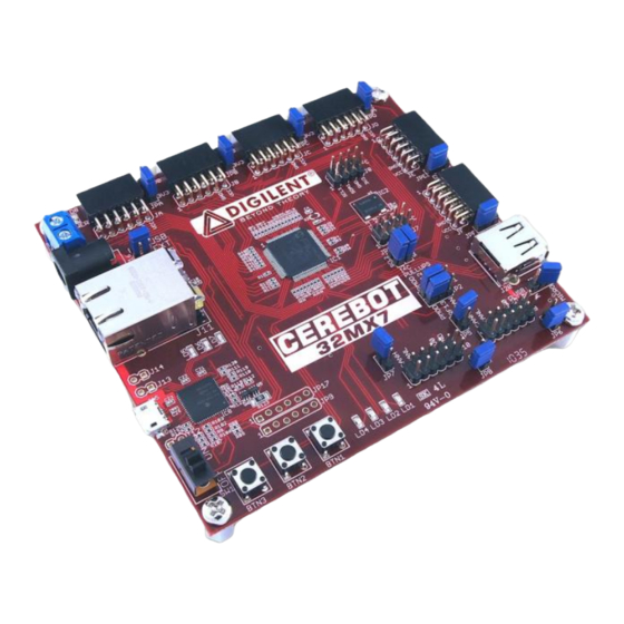
The Cerebot 32MX7 board is a useful tool for
embedded control and network
communications projects for both students and
hobbyists.
Its versatile design and programmable
microcontroller lets you access numerous
peripheral devices and program the board for
multiple uses. The board has many I/O
connectors and power supply options. It‟s
network and communications features include
10/100 Ethernet interface, Full Speed USB 2.0
OTG interface, dual CAN network interfaces,
dual I2C buses, up to three UART ports and up
to three SPI ports.
The Cerebot 32MX7 works with the Microchip
MPLAB development environment and
provides built in programming and debugging
support within MPLAB.
The Cerebot 32MX7 provides a number of
connections for peripheral devices. It has six
connectors for attaching Digilent Pmod™
peripheral modules. Digilent peripheral
modules include H-bridges, analog-to-digital
and digital-to-analog converters, speaker
amplifier, switches, buttons, LEDs, as well as
converters for easy connection to RS232,
screw terminals, BNC jacks, servo motors, and
more.
Features include:
a PIC32MX795F512L microcontroller
support for programming and
debugging within the Microchip MPLAB
development environment
six Pmod connectors for Digilent
peripheral module boards
10/100 Ethernet
USB 2.0 Device, Host, and OTG
support
two CAN network interfaces
Doc: 502-186
Copyright Digilent, Inc. All rights reserved. Other product and company names mentioned may be trademarks of their respective owners.
™
™
X
7
B
o
a
r
d
X
7
B
o
a
r
d
a
n
u
a
l
a
n
u
a
l
1300 Henley Court | Pullman, WA 99163
(509) 334 6306 Voice and Fax
three push buttons
four LEDs
multiple power supply options, including
USB powered
ESD protection and short circuit
protection for all I/O pins.
Cerebot 32MX7 Circuit Diagram
page 1 of 17
Advertisement
Table of Contents

Subscribe to Our Youtube Channel
Related Manuals for Digilent Cerebot 32MX7


Summary of Contents for Digilent Cerebot 32MX7
- Page 1 10/100 Ethernet USB 2.0 Device, Host, and OTG support two CAN network interfaces Doc: 502-186 page 1 of 17 Copyright Digilent, Inc. All rights reserved. Other product and company names mentioned may be trademarks of their respective owners.
-
Page 2: Functional Description
Microchip MPLAB development environment. to the board: USB powered from the debug In-system-programming and debug of firmware www.digilentinc.com page 2 of 17 Copyright Digilent, Inc. All rights reserved. Other product and company names mentioned may be trademarks of their respective owners. - Page 3 In addition to powering the logic on the power select jumpers for the Pmod connectors. www.digilentinc.com page 3 of 17 Copyright Digilent, Inc. All rights reserved. Other product and company names mentioned may be trademarks of their respective owners.
-
Page 4: Usb Interface
Jumper JP10 is used to route power to the host connector being used. Place the shorting www.digilentinc.com page 4 of 17 Copyright Digilent, Inc. All rights reserved. Other product and company names mentioned may be trademarks of their respective owners. -
Page 5: Ethernet Interface
MAC/PHY interface. interface signaling conventions. The Cerebot 32MX7 is designed to use the standard (not www.digilentinc.com page 5 of 17 Copyright Digilent, Inc. All rights reserved. Other product and company names mentioned may be trademarks of their respective owners. -
Page 6: Can Interfaces
Jumper JP5 is used to www.digilentinc.com page 6 of 17 Copyright Digilent, Inc. All rights reserved. Other product and company names mentioned may be trademarks of their respective owners. -
Page 7: Pmod Connectors
I/O interfaces. The Pmod line includes such www.digilentinc.com page 7 of 17 Copyright Digilent, Inc. All rights reserved. Other product and company names mentioned may be trademarks of their respective owners. -
Page 8: Cpu Clock Source
The four LEDs are connected to bits 12-15 of PORTG. LED 1 is connected to bit 12, LED 2 www.digilentinc.com page 8 of 17 Copyright Digilent, Inc. All rights reserved. Other product and company names mentioned may be trademarks of their respective owners. - Page 9 RD03 OC4/RD3 JD-09 RD04 OC5/PMWR/CN13/RD4 JC-09 RD05 PMRD/CN14/RD5 JC-08 RD06 ETXEN/PMD14/CN15/RD6 Ethernet PHY RD07 ETXCLK/PMD15/CN16/RD7 JC-04 www.digilentinc.com page 9 of 17 Copyright Digilent, Inc. All rights reserved. Other product and company names mentioned may be trademarks of their respective owners.
- Page 10 …/SS2A/U2BRX/U2ACTS/PMA2/CN11/RG9 RG09 Ethernet PHY RG12 TRD1/RG12 LED1 RG13 TRD0/RG13 LED2 RG14 TRD2/RG14 LED3 RG15 AERXERR/RG15 LED4 www.digilentinc.com page 10 of 17 Copyright Digilent, Inc. All rights reserved. Other product and company names mentioned may be trademarks of their respective owners.
- Page 11 SDA3A/SDI3A/U3ARX/PMA9/CN17/RF4 RF04 JF-04 AC1TX/SCK3A/U3BTX/U3ARTS/RF13 RF13 shared with CAN1 Transceiver (JP-2) JF-07 TMS/RA0 RA00 JF-08 TCK/RA1 RA01 www.digilentinc.com page 11 of 17 Copyright Digilent, Inc. All rights reserved. Other product and company names mentioned may be trademarks of their respective owners.
- Page 12 …/SS2A/U2BRX/U2ACTS/PMA2/CN11/RG9 RG09 Ethernet PHY TRD1/RG12 RG12 LED1 TRD0/RG13 RG13 LED2 TRD2/RG14 RG14 LED3 AERXERR/RG15 RG15 LED4 www.digilentinc.com page 12 of 17 Copyright Digilent, Inc. All rights reserved. Other product and company names mentioned may be trademarks of their respective owners.
- Page 13 D- (USB-2) RG02 D+/RG2 D+ (USB-3) RA02 SCL2/RA2 I2C Bus #2, not shared with Pmod connector www.digilentinc.com page 13 of 17 Copyright Digilent, Inc. All rights reserved. Other product and company names mentioned may be trademarks of their respective owners.
- Page 14 LED3 RG12 TRD1/RG12 LED1 RG13 TRD0/RG13 LED2 RE02 PMD2/RE2 JB-03 RE03 PMD3/RE3 JB-04 RE04 PMD4/RE4 JB-07 www.digilentinc.com page 14 of 17 Copyright Digilent, Inc. All rights reserved. Other product and company names mentioned may be trademarks of their respective owners.
- Page 15 This is a USB micro-AB connector. It is used when using the PIC32MX795 microcontroller to implement a USB device or OTG Host/Device. www.digilentinc.com page 15 of 17 Copyright Digilent, Inc. All rights reserved. Other product and company names mentioned may be trademarks of their respective owners.
- Page 16 Digilent Pmod peripheral modules can be attached to these connectors. JPA – Pmod header power select www.digilentinc.com page 16 of 17 Copyright Digilent, Inc. All rights reserved. Other product and company names mentioned may be trademarks of their respective owners.
- Page 17 3V3. To use unregulated power, place the jumper block over the center pin and the pin marked 5V0. www.digilentinc.com page 17 of 17 Copyright Digilent, Inc. All rights reserved. Other product and company names mentioned may be trademarks of their respective owners.
Need help?
Do you have a question about the Cerebot 32MX7 and is the answer not in the manual?
Questions and answers